저작자표시-비영리-변경금지 2.0 대한민국 이용자는 아래의 조건을 따르는 경우에 한하여 자유롭게
l 이 저작물을 복제, 배포, 전송, 전시, 공연 및 방송할 수 있습니다. 다음과 같은 조건을 따라야 합니다:
l 귀하는, 이 저작물의 재이용이나 배포의 경우, 이 저작물에 적용된 이용허락조건 을 명확하게 나타내어야 합니다.
l 저작권자로부터 별도의 허가를 받으면 이러한 조건들은 적용되지 않습니다.
저작권법에 따른 이용자의 권리는 위의 내용에 의하여 영향을 받지 않습니다. 이것은 이용허락규약(Legal Code)을 이해하기 쉽게 요약한 것입니다.
Disclaimer
저작자표시. 귀하는 원저작자를 표시하여야 합니다.
비영리. 귀하는 이 저작물을 영리 목적으로 이용할 수 없습니다.
변경금지. 귀하는 이 저작물을 개작, 변형 또는 가공할 수 없습니다.
공학석사 학위논문
Optimal Layout Method of an Offshore Plant Topside Based on
Expert System
전문가 시스템 기반 해양 플랜트 상부의 최적 배치 방법
2016년 2월
서울대학교 대학원 조선해양공학과
김 성 균
Abstract
Optimal Layout Method of an Offshore Plant Topside Based on the Expert System
In an offshore plant, many modules and equipment are placed on the limited space called topside, so that the space should be used efficiently. Furthermore, a sufficient space between equipment should be provided for the operability, maintainability, and safety. To guarantee suitable arrangement design, there are many requirements to be considered such as international codes and standards, including owners’ own requirements. Also, the arrangement design of an offshore plant topside tends to rely on experts’ knowledge and experiences. In this study, an arrangement method of offshore plant topside based on the expert system and the optimization technique was proposed to obtain the optimal layout which satisfies many requirements as mentioned above. Proposed method consists of four component. First, an expert system that can systematically computerize experts’ knowledge and experiences, and can evaluate the feasibility of alternatives for the arrangement design of the offshore plant topside was proposed by expanding the previous study of authors for the arrangement design of a submarine. Second, an arrangement template model (ATM) was proposed to store various data on the arrangement design of the offshore plant topside. Third, an optimization method that can yield a better arrangement design was proposed by formulating a topside arrangement problem as optimization problem. Forth, user interface was developed for expert system and optimization. To evaluate the applicability of the proposed arrangement method, a prototype program was also developed here. Finally, this program was applied to a problem of a large FPSO topside. The results showed that the proposed method can be used to obtain
the optimal arrangement of offshore plant topside.
Keywords: Arrangement design; offshore plant topside; Expert system;
Optimization, Arrangement evaluation model Student number: 2014-20646
Contents
Abstract ... i
Introduction ... 1
1.1. Arrangement design of offshore plant topside ... 1
1.2. Research background ... 3
1.3. Related works ... 5
1.4. Target of this study ... 9
1.5. Summary of this study ... 11
1.5.1. Overview ...11
1.5.1. Arrangement template model (ATM) ...11
1.5.2. Arrangement evaluatiom model (AEM) ...12
1.5.3. Arrangement optimization model (AOM) ...12
1.5.4. User interface ...13
Arrangement template model (ATM) for the arrangement design of an offshore plant topside . 14 Arrangement evaluation model (AEM) for the arrangment design of offshore plant topside ... 17
3.1. Representation of object information ... 19
3.2. Representation of relation information ... 23
3.3. Arrangement evaluation ... 28
3.4. Weight factor for the rules ... 32
Arrangement optimization model (AOM) for the
arrangement design of an offshore plant topside . 34
4.1. Optimization of the module arrangement ... 36
4.1.1. Input data ...36
4.1.2. Design variables ...38
4.1.3. Objective functions ...38
4.2. Optimization of the equipment arrangement in the module ... 40
4.2.1. Input data ...40
4.2.2. Design variables ...41
4.2.3. Objective functions ...43
4.2.4. Constraints ...48
User interface ... 51
5.1. Configuration of user interface ... 51
5.2. Tool for expert system ... 52
5.3. Tool for optimization ... 53
Applications ... 54
6.1. Optimal module layout ... 54
6.1.1. Experts’ knowledges for application ...55
6.1.2. Result ...57
6.1.3. Case study ...59
6.2. Optimal equipment layout in water injection module ... 60
6.2.1. Input data ...60
6.2.2. Experts’ knowledges for application ...62
6.2.3. Result ...63
6.2.4. Case study ...65
6.3. Optimal equipement layout in separation module ... 69
6.3.1. Input data ...69
6.3.2. Experts’ knowledges for application ...70
6.3.3. Result ...70
6.4. Optimal equipment layout in oil cooling module ... 72
6.4.1. Input data ...72
6.4.2. Experts’ knowldeges for application ...73
6.5.2. Experts’ knowledges for application ...77
6.5.3. Result ...77
6.6. Optimal equipment layout in gas compression module ... 79
6.6.1. Input data ...79
6.6.2. Experts’ knowledge for application ...81
6.6.3. Result ...83
Conclusions and future works ... 85
References ... 86
APPENDICES... 88
A. Oil and gas production process ... 89
A.1. Overall process flow ... 89
A.2. Oil production system ... 91
A.3. Gas production system ... 93
A.4.Produced water system ... 95
B. International code and standard ... 96
B.1. API RP 14J ... 96
B.1.1 General ...96
B.1.2. Separation of fuel and ignition sources ...97
B.1.3. Adequate ventilation ...97
B.1.4. Platform equipment arrangement ...97
B.2. NORSOK Standard, L-002 ... 102
B.2.1. General ... 102
B.2.2. Miscellaneous requirements ... 103
B.3. NORSOK Standard, P-100 ... 104
B.3.1. Crude handling (system 21) ... 104
B.3.2. Ga compression (system 23, 26 & 27) ... 104
B.3.3. Water injection system (system 29) ... 104
B.3.4. Cooling medium (system 40) ... 105
B.3.5. Heating medium (system 41) ... 105
B.3.6. Chemical injection (system 42) ... 105
B.3.7. Flare system ( system 43) ... 105
B.3.8. Oil water treatment (system 44) ... 106
B.3.9. Diesel oil (system 62) ... 106
B.3.10. Compressed air (system 63) ... 106
B.4. NORSOK Standard, S-001 ... 107
B.4.1. Riser flow line area ... 107
B.4.2. Process area ... 107
B.4.3. Piping ... 108
B.4.4. Lifting and laydown ... 108
국문 초록 ... 109
Figures
Figure 1-1 Example of the arrangement an FPSO (Salzgitter Mannesmann Stainless
Tubes, 2015) ... 2
Figure 1-2 Configuration of the proposed arrangement method of an offshore plant topside based on the expert system and optimization technique ... 11
Figure 2-1 Arrangement template model (ATM) expressed by using UML ... 16
Figure 3-1 Configuration of the arrangement evaluation model ... 18
Figure 3-2 Configuration of the object information ... 19
Figure 3-3 Examples of the object information... 22
Figure 3-4 Configuration of the relation information ... 23
Figure 3-5 Example of the relation information of using the "GroupWith" and “ConnectionTo” type ... 26
Figure 3-6 Example of the relation information of using the “DistanceFrom” and “LevelDifference” ... 27
Figure 3-7 Example of the converting procedure of the object information to rules ... 30
Figure 3-8 Example of the converting procedure for the relation information to rules ... 31
Figure 3-9 Example: effects of the weight factor ... 33
Figure 4-1 Configuration of the two stages optimization problem for the arrangement design of the FPSO topside ... 35
Figure 4-2 Representation of the positions of each module ... 38
Figure 4-3 Design variable for equipment arrangement ... 42
Figure 4-4 Calculation procedure of the probability of the damage. Pij (Park, 2011) ... 45
Figure 4-5 Empty volume of the kth deck ... 47
Figure 4-6 Passage constraints: limits of the passage location ... 50
Figure 5-1 Screenshot of the prototype program ... 51
Figure 5-2 Screenshot of the prototype program: tool for the object and relation information ... 52
Figure 5-3 Screenshot of the prototype program: tool for the expert system ... 52
Figure 5-4 Screenshot of the prototype program: tool for the optimization ... 53
Figure 6-1 Optimal module arrangement ... 58
Figure 6-2 Case study: effect of the rule to the module arrangement ... 59
Figure 6-3 Flow diagram; Water injection system ... 61
Figure 6-4 Constraints for “Deaeration tower” as multi-deck equipment ... 62
Figure 6-5 Visualization of the optimal equipment arrangement in “Water injection” module ... 65
Figure 6-6 Case study: effect of the rule to the equipment arrangement in “Water injection” module ... 66
Figure 6-7 Visualization of the optimal result including the internal transverse passages ... 68
Figure 6-8 Flow diagram; Separation module ... 69
Figure 6-9 Visualization of optimal result; Separation module ... 71
Figure 6-10 Flow diagram; Oil cooling module ... 72
Figure 6-11 Visualization of optimal result; Oil cooling module ... 75
Figure 6-12 Flow diagram; Oil exporting module ... 76
Figure 6-13 Visualization of optimal result; Oil exporting module ... 78
Figure 6-14 Flow diagram; Gas compression module ... 80
Figure 6-15 Visualization of optimal result; Gas compression module ... 84
Figure A-1 Overall process flow (Angus Mather, 2009) ... 89
Figure A-2 Process flow of oil production system ... 91
Figure A-3 Incremental liquid recovery versus number of separator stages (Ken Arnold et at., 2008)... 92
Figure A-4 Process flow of gas production system ... 93
Figure A-5 process flow of produced water system ... 95
Figure B-1 Fuel and ignition sources ... 98
Tables
Table 1-1 Summary of related works ... 8
Table 2-1 Properties of the topside class ... 15
Table 2-2 Properties of the module class ... 15
Table 2-3 Properties of the deck class ... 15
Table 2-4 Properties of the equipment class ... 16
Table 2-5 Properties of the passage class ... 16
Table 3-1 Properties of the object information ... 21
Table 3-2 Description of attributes of the object information ... 21
Table 3-3 Data type and properties of the target value according to the attributes . 21 Table 3-4 Properties of the relation information ... 24
Table 3-5 Description of relation types of the relation information ... 24
Table 3-6 Data type and properties of the target value according to the relation type ... 25
Table 4-1 Input data for the module arrangement ... 37
Table 4-2 Objective functions for the optimization of the module arrangement ... 39
Table 4-3 Input data for the equipment arrangement ... 41
Table 4-4 Design variables for the equipment arrangement ... 42
Table 6-1 Module list of the example FPSO topside ... 54
Table 6-2 Object list for the module arrangement ... 56
Table 6-3 Relation list for the module arrangement ... 56
Table 6-4 Comparison of the objective functions with the manual design ... 58
Table 6-5 Equipment list; Water injection module ... 61
Table 6-6 Object list for the equipment arrangement in “Water injection” module 63 Table 6-7 Relation list of the equipment arrangement in “Water injection” module ... 63
Table 6-8 Comparison of the objective functions with the manual design ... 64
Table 6-9 Result of the optimal equipment arrangement ... 64
Table 6-10 Additional object information ... 66
Table 6-11 Comparison: with internal passage vs without internal passage ... 67
Table 6-12 Result of the optimal equipment arrangement with internal passages .. 68
Table 6-13 Equipment list; Separation module ... 69
Table 6-14 Object list for equipment arrangement; Separation module ... 70
Table 6-15 Objective functions and optimum values; Separation module ... 70
Table 6-16 Result of optimal equipment arrangement; Separation module ... 71
Table 6-17 Equipment list; Oil cooling module ... 72
Table 6-18 Object list for equipment arrangement; Oil cooling module ... 73
Table 6-19 Relation list for equipment arrangement; Oil cooling module ... 74
Table 6-20 Objective functions and optimum values; Oil cooling module ... 74
Table 6-21 Result of optimal equipment arrangement; Oil cooling module ... 74
Table 6-22 Equipment list; Oil exporting module ... 76
Table 6-23 Object list for equipment arrangement; Oil exporting module ... 77
Table 6-24 Objective functions and optimum values; Oil exporting module ... 77
Table 6-25 Result of optimal equipment arrangement; Oil exporting module ... 78
Table 6-26 Equipment list; Gas compression module ... 80
Table 6-27 Object list for equipment arrangement; Gas compression module ... 82
Table 6-28 Objective functions and optimum values; Gas compression module .... 83
Table 6-29 Result of optimal equipment arrangement; Gas compression module .. 83
Introduction
1.1. Arrangement design of offshore plant topside
An offshore plant is a large facility which produces oil and gas from offshore oil and fields. The offshore plant has the limited space called topside, as compared with an onshore plant. Many modules and equipment are placed on the topside. Thus, the space should be used more efficiently and compactly. Furthermore, a sufficient space should be provided for convenient operation and easy maintenance of the modules and equipment. In addition, the safety is a critical issue as accidents would result in significant losses of human lives and properties, and cause huge environmental impact. As a result, an arrangement design of the offshore plant topside is one of key processes of engineering activities for constructing the offshore plant in order to achieve the operability, maintainability, and safety.
Among various types of the offshore plant, an FPSO (Floating, Production, Storage, and Offloading unit) is a representative type which produces oil and gas in deep water. It is made up of two parts: topside and hull. The topside, like chemical plants, produces and offloads crude oil and gas, and the hull, like big tanks, stores the produced oil (Hwang et al., 2010). In the FPSO topside, various modules and equipment are installed in order to separate oil, gas, and water from well fluid, to produce oil and gas, to store them in internal tanks of the hull, and to offload them on other ships. Here, a module (e.g., separator, living quarter, flare tower, etc.) can be regarded as a system or a group of equipment which performs a specific function such as separation, accommodation, gas combustion, and so on. And the module includes several equipment. In the module, the equipment are located on several decks, that is, multiple decks, in order to use the limited space efficiently and
compactly. That is, the FPSO topside includes several modules having specific functions. In the module, many equipment are installed on multiple decks. Each module is constructed individually and integrated with the FPSO hull in the shipyard.
Thus, the arrangement design of the FPSO topside can be divided into two stages (Ku et al., 2014). The first stage is the module arrangement. For example, considering the prevailing wind direction, a living quarter should be arranged upwind, and a flare tower should be arranged as far as possible to the living quarter.
Utility service modules such as a water injection module and an electric power generation module should be arranged between the living quarter and hazardous modules to serve as a barrier. The second stage is the equipment arrangement in the module. At this time, a process flow should be considered to reduce the piping length among equipment. Moreover, a space for operation and maintenance around the equipment should be considered. Figure 1-1shows an example of the arrangement of an FPSO topside (Salzgitter Mannesmann Stainless Tubes, 2015).
1.2. Research background
There are many international codes and standards providing the general guidance and criteria for the arrangement design of an offshore plant topside. And owners have their own requirements based on their operational philosophy and site characteristics of the offshore plant. Consequently, the arrangement design should satisfy the international codes and standards, and the owners’ requirements without their omissions. Meanwhile, the arrangement design mainly depends on experts’
own knowledge and experiences. Delay in design can occur when there are missing considerations or when experts are absent. Therefore, experts’ knowledge and experiences is also required to be reflected in arrangement design properly.
At this time, there are many design methods and tools available to support a designer. Some of them are now available as commercial computer programs (Edwards, 2003). However, design of a product is no longer considered as a problem solving procedure. With the initiation of technology and competent programs for computation, it has become more of a decision making process that involves precise assessment of design alternatives (Ipek et al., 2012). Thus, an expert system can be one of the alternative solutions to such problem or process. There are several researches adopting the expert system to an arrangement problem. The expert system is a branch of the applied artificial intelligence. The basic idea behind the system is simplifying that expertise, which is the vast body of task-specific knowledge, is transferred from a human to computer. This knowledge is then stored in the computer and a designer call upon the computer for specific advice as needed (Liao, 2005). If the expert system is well developed and is applied in the stage of arrangement design, it can be used to evaluate the feasibility of an arrangement design alternative instead of relying on experts for each design alternative. Thus, an expert system that can systematically computerize experts’ knowledge, and can evaluate the feasibility of
alternatives for the arrangement design of an offshore plant topside was developed, and it is consolidated in optimization technique to derive the optimal layout of an offshore plant topside.
1.3. Related works
Arrangement design method has been proposed by several authors. And the expert system has been adopted for various fields of research. In this section, a summary of the past studies, related to the arrangement design in the fields including naval architecture and ocean engineering, is described.
In the field of the ship design, Byun (1998) proposed a rule-based expert system based on a knowledge base for supporting initial ship design such as compartment design at the initial design stage. He constructed a knowledge base for deciding principal dimensions of a ship to obtain the maximum volume of cargo that can be carried by a ship as per the owner’s requirements and the pertinent international regulations. In addition, he constructed a knowledge base for determining the arrangement of compartments. Shin et al. (2002) proposed an expert system for the arrangement design of machinery in a ship. They made rules for the arrangement design of the machinery, from the relation between the equipment to the owner’s requirements, the insights of the designer, etc. When evaluating the rules for coming up with design alternatives, they also considered fuzzy rules. Finally, they developed a new algorithm for the arrangement design of the machinery using the expert system.
Helvacioglu and Insel (2005) proposed a multistage expert system for the arrangement design of compartments of a container ship. With the expert system, they divided a container ship into several large blocks called function groups, and initially arranged them to determine the compartment arrangement. By considering more detailed data, they derived the final arrangement of the compartments of the container ship. They used heuristic knowledge and rules for the container ship in the expert system. Chung et al. (2011) proposed an optimization method of compartments in the pressure hull of a submarine with a rule-based expert system.
The rule-based expert system was adopted to evaluate alternatives for the
arrangement design of the submarine. The evaluation values called feasibility indices for the alternatives obtained from the expert system were used as an objective function for optimization. If a certain alternative violates a rule, a positive penalty is added to the value of the objective function of the alternative. Shin (2013) proposed a method for the arrangement design of a naval ship by considering its survivability at the initial design stage. The SLP (Systematic Layout Planning) method was used for analyzing the relation between the equipment in the naval ship. Then an arrangement method for generating alternatives and evaluating the feasibility of them was proposed. The SLP method differs from the expert system in that the method decides the arrangement using the relation matrix between the equipment, but as such matrix is made by an expert, it is somewhat similar to the expert system.
We proposed an expert system based on an arrangement evaluation model (AEM) for the arrangement design of a submarine in the previous study (Kim et al., 2015).
The AEM was proposed as an expansion of the rule-based expert system. In addition, an arrangement template model (ATM) for the submarine was proposed to store the arrangement data of the submarine.
In field of the onshore and offshore plant design, Patisatizis et al. (2002) proposed an optimal layout method for multi-floor process plant. Arrangement method for multi-floor process plant was formulated as optimization problem. It applied to the five-unit instant coffee process and ethylene oxide plant. Park et al. (2011) proposed an optimal layout method with consideration of the safety distance based on the TNT equivalency method. Physical explosion of the pressurized vessel was considered.
Proposed method was applied to the ethylene oxide plant and benzene production plant. Ku et al. (2014) proposed an optimal arrangement method for a generic
et al. (2015) proposed an optimal arrangement method of an FPSO topside.
Optimization problems for the module arrangement and the equipment arrangement were formulated and then solved with the genetic algorithm. Above studies proposed the optimal arrangement method of the offshore plant topside which regards various arrangement considerations such as experts’ knowledge as constraints during optimization process. However, it is difficult to reflect additional considerations or changes on the existing problems flexibly and efficiently without the modification of the optimization problems. Dan et al. (2015) performed the layout optimization of LNG-liquefaction process on LNG-FPSO preventing domino effects. Considering the jet fire, vapor cloud explosion (VCE) and physical explosion, safety distance was calculated, then it was reflected in non-overlapping constraints. Also protection devices such as water curtain was considered in mathematical formulation of the optimization. However, various requirement for arrangement design was not reflected into the layout optimization efficiently.
In the fields of other design, Park (2009) proposed a framework for representing experts’ knowledge called SLEM (Spatial Layout Evaluation Model) using the requirement of space (area, position, etc.) and the relation between the spaces (adjacency, level difference, etc.). Then he evaluated the given arrangement for a building using the proposed framework. Such method, however, could evaluate the building special section only. Thus, it has limitation to evaluate the arrangement of an interior or equipment in the building.
Table 1-1 shows a summary of the related works and a comparison of such works with this study. In the table, the application target and evaluation method of each research were organized.
Table 1-1 Summary of related works
Research Target of application Template model
Expert system
Optimiz ation
Problem type
Byun (1998) Ship compartments X O X 2D
Patisiatizis et al. (2002)
Instant coffee process
Ethylene oxide plant X X O 3D
Shin et al.
(2002) Ship machinery X O X 3D
Helvacioglu
& Insel (2005)
Ship compartments X O X 2D
Park (2009) Building sections X O X 3D
Chung et al.
(2011) Submarine X O O 2D
Part et al.
(2011)
Ethylene oxide plant Benzene production plant
X X O 3D
Shin et al.
(2013) Naval ship X O X 3D
Ku et al.
(2014) LNG FPSO topside X X O 3D
Jeong et al.
(2015) FPSO topside X X O 3D
Dan et al.
(2015) LNG FPSO topside X X O 3D
Kim et al.
(2015) Submarine O O X 3D
This study FPSO topside O O O 3D
1.4. Target of this study
Among the various type of the offshore plant, this study proposed the arrangement method of FPSO. Through the literature survey of the prior section, it can be seen that most of the relevant researches have focused on the expert system or optimization individually. In this study, the expert system and optimization were combined to derive the optimal arrangement design satisfying the various layout requirements. First, as a data structure, arrangement template model (ATM) was newly proposed to store the arrangement information. Second, and expert system for arrangement design of offshore plant topside was developed. An expert system for a three-dimensional arrangement design for an offshore plant topside has not been studied yet. A rule-based expert system, a kind of the expert system, is defined as one, which contains information obtained from experts, and represents that information in the form of rules, such as IF-THEN phrases (Liao, 2005). As mentioned earlier, we proposed the AEM that can systematically computerize experts’ knowledge for the arrangement design of a submarine by extending the existing rule-based expert system in the previous study (Kim et al., 2015). In this study, the AEM for the arrangement design of an offshore plant topside was proposed to evaluate the feasibility of the arrangement alternatives. Third, arrangement problem of the FPSO topside, was formulated as optimization problem.
The feasibility from the expert system was used as one of objective functions in optimization stage.
The reminder of this paper is organized as follows. Section 2 describes the arrangement template model (ATM) for offshore plant topside proposed in this study.
Section 3 describes the expert system for arrangement design of the offshore plant topside, based on the arrangement evaluation model (AEM). Section 4 describes the arrangement optimization model (AOM). In this study, arrangement design of the
offshore plant topside is formulated as optimization problems. Section 5 describes the user interface developed in this study. In Section 6, the application of the proposed arrangement method to an FPSO is presented with discussion the application results. The last section mentions the results of this study and briefly discusses the next study. Additionally, process flow of the FPSO topside is attached as appendix A. Arrangement requirement recommended by various international codes and standards are summarized in appendix B.
1.5. Summary of this study
1.5.1. Overview
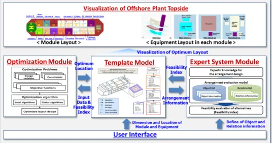
In this paper, arrangement design method of an offshore plant topside based on the expert system and the optimization technique was proposed. Figure 1-2 shows the configuration of the proposed method. As shown in this figure, the proposed method consists of four components: the arrangement template model, the expert system module, the optimization module, and the user interface.
Figure 1-2 Configuration of the proposed arrangement method of an offshore plant topside based on the expert system and optimization technique
1.5.1. Arrangement template model (ATM)
A data structure that can store the arrangement data is required to perform the arrangement design of the offshore plant topside. In this study, the ATM, that is, the data structure for the arrangement design of the offshore plant topside was defined hierarchically by using UML (Unified Modeling Language) in order to store various
data related to the arrangement design of the offshore plant topside such as topside, modules, equipment, decks, passages, and so on.
1.5.2. Arrangement evaluatiom model (AEM)
The AEM can be regarded as a general rule-based expert system. Thus, it includes some components of the rule-based expert system such as a knowledge base, a database, and an inference engine, and so on. One of the difference between the AEM and the general rule-based expert system is that the knowledge base and the database are integrated with management as two lists called object and relation lists (Kim et al., 2015). In this study, AEM is used to evaluate the feasibility of alternatives for the arrangement design of the offshore plant topside. With the AEM, a designer can easily express various rules about the arrangement design of the offshore plant topside, and evaluate the feasibility of the given design alternative.
1.5.3. Arrangement optimization model (AOM)
In this study, optimization technique was used to derive the arrangement design of an offshore plant topside. Thus, optimization module was developed. It includes the mathematical formulation of optimization problems and an optimization algorithm for solving the formulated problems. As described in section 1.1, the arrangement design of the FPSO topside can be divided into two stages. Thus, the arrangement design of the FPSO topside was formulated as two stages optimization problems. First stage is the module arrangement. Module arrangement problem was
equipment arrangement in each module. Process flow, possibility of the physical explosion and ventilation were considered to formulate the equipment arrangement problem as optimization problem.
Optimization module uses the dimension and location information of modules and equipment stored in ATM. Various requirement for the arrangement design of the offshore plant topside can be expressed as rules in the expert system. Expert system returns the feasibility index to optimization module. Optimization module uses the feasibility index as one of the objective functions.
1.5.4. User interface
A user interface is also needed for a designer to use above components flexibly.
In this study, the user interface which consists of two components was developed and then used to evaluate the arrangement design of the offshore plant topside; tool for expert system, and 3D visualization panel. The first component is used to create, edit, and operate experts’ rules. And the second component is used to investigate and visualize the arrangement result of the offshore plant topside.
Arrangement template model (ATM) for the arrangement design of an offshore plant topside
As mentioned earlier, an offshore plant like an FPSO consists of two parts:
topside and hull. The topside, like chemical plants, produces and offloads crude oil and gas, and the hull, like big tanks, stores the produced oil (Hwang et al., 2010). In the aspects of the production of oil and gas and the difficulty of the arrangement design, the topside is more important than the hull. Thus, this study focused on the arrangement design of the topside. As shown in Figure 2-1, the topside includes several modules having specific functions. In the module, many equipment are installed on multiple decks for the efficient, compact use of the topside.
The overall procedure for the arrangement design of the topside is as follows.
First, the topside is defined, and it is divided into several modules. For the efficient arrangement of equipment and passages in the module, the module is further divided into several regions through the use of multiple decks. Finally, the equipment and passages are defined and arranged to the decks.
To store the arrangement data such as those pertaining to the topside, modules, decks, equipment, and passages, a space for them called the arrangement template model (ATM) was defined hierarchically in this study. This space is a kind of a data structure, which is necessary for most computer programs. To define the model, the UML was used in this study. The UML is a language for specifying, visualizing, constructing, and documenting the products of software systems, as well as for
Topside class has the list of the module arranged in topside. In the module class, name, size such as the length, width and height, COG, deck and equipment list installed in each module are stored. In the deck class, length, width, height and list of equipment installed in each deck are stored. In equipment and passage class, length, width, height and COG are stored. Properties of each class are summarized from Table 2-1 to Table 2-5.
Table 2-1 Properties of the topside class
Topside
Properties Data type
Modules List<module>
Table 2-2 Properties of the module class
Module
Properties Data type
Name String
Length Double
Width Double
Height Double
COG Point
Decks List<deck>
Equipment List<equipment>
Table 2-3 Properties of the deck class
Deck
Properties Data type
Name String
Length Double
Width Double
Zpos Double
COG Point
Equipment List<equipment>
Table 2-4 Properties of the equipment class
Equipment
Properties Data type
Name String
Length Double
Width Double
Height Double
COG Point
Weight Double
Equipment type enum
Table 2-5 Properties of the passage class
Passage
Properties Data type
Name String
Length Double
Width Double
Height Double
COG Point
Arrangement evaluation model (AEM) for the arrangment design of offshore plant topside
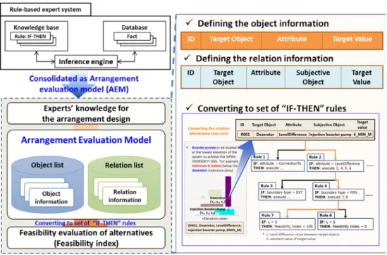
The configuration of the rule-based expert system and the AEM are represented in Figure 3-1. In the rule-based expert system, a rule is defined as the “IF-THEN”
phase, and stored in a knowledge base. An inference engine compares the “IF” phase of the rule in the knowledge base with the fact in a data base (called pattern matching).
If the “IF” part of the rule is same as the “Fact” in the database, then the “THEN”
part of the rule in the knowledge base are stored in the data base as a new fact.
The knowledge base, the data base, and the inference engine are consolidated as the AEM in this study. Rules derived from experts’ knowledge or experiences are expressed as object information and relation information. The experts’ knowledge about property requirements for a specific object are expressed as the object information. And the experts’ knowledge about the relation between specific objects are expressed as the relation information. The object and relation information are defined as combination of the several properties. A group of the object and relation information are named as an object list and a relation list, respectively. Thus, it can be seen that the AEM is based on the object and relation lists.
The AEM converts the object and relation information in the object and relation lists as rules of IF-THEN phrases. In this meaning, the AEM can be a kind of the rule-based expert system. Referring to the converted rules of IF-THEN phrases, a feasibility index of the given alternative for the arrangement design can be evaluated.
The feasibility index is a certain value quantitatively scoring the compliance with the rules in the object and relation information. In this study, the AEM for the arrangement design of an offshore plant topside was proposed. With this model and the object and relation lists, various rules about the arrangement design of the
offshore plant topside can be easily expressed, and the feasibility of the given design alternative can be evaluated.
As shown in Figure 3-1, the AEM corresponds to the knowledge base, database, and inference engine of the rule-based expert system. Thus, a designer does not have to consider the complicated inference process when making the rules for the arrangement design with the use of the AEM. In this sense, the AEM can be regarded as an extended, advanced version of the rule-based expert system for use in the arrangement design of an offshore plant topside.
Figure 3-1 Configuration of the arrangement evaluation model
3.1. Representation of object information
The object information can express experts’ knowledge about requirements for a specific object in the offshore plant topside such as a module, equipment, and so on.
If an expert possesses the knowledge that “the separator should be arranged along the longitudinal direction of the offshore plant,” it can be represented as one objective information. The keywords in the knowledge are the target object (e.g.,
“separator”), the attribute (e.g., “orientation”), and the target value (e.g., “1_EXT”).
Adding an ID (e.g., “E001”) to each distinct rule, one object information can be represented with four properties: the ID, target object, attribute, and target value.
Here, the target value is used to give a certain value to the object. Again, the target value can be defined with three sub-key words: standard value (e.g., “1”), boundary type (e.g., “EXT” for exact), and unit type (e.g., none for this example). An example of object information is shown in Figure 3-2. The set of object information for all the objects defined in the domain is called an object list in this study.
Figure 3-2 Configuration of the object information
To use four properties (ID, target object, attribute, and target value) in the AEM, they have to be specified by a suitable data type for them, as shown in Table 3-1.
The ID and target object can be expressed by a string type to distinct the target object for the object information. The attribute represents properties of the target object, and it can be certain words like “Order”, “Orientation”, “COG.x”, “COG.y”,
“COG.z”, “Volume”, “Area”, and so on. Using an enumerator composed of those kinds of words, we can express the attribute. The description of attributes of the
object information is listed in Table 3-2. And the target value can be expressed by a new type which is called metric type. In this study, the metric type is used to represent the target value for the object information and the relation information.
As mentioned earlier, the metric type is composed of three sub-key words;
standard value, boundary type, and unit type. The standard value is used to specify a certain value for the target value, and it can be expressed by double or integer of data type.
The boundary type represents the limit of the target value, and it can be certain words like “EXT” for exact value, “MAX” for maximum value, “MIN” for minimum value, and “PRO” for proposed value. Using an enumerator composed of those kinds of words, we can express the boundary type.
The unit type is a unit of the standard value. And it also can be expressed by using an enumerator. In this study, SI unit is used, thus m, m2, m3 and so on are included in the unit type. Of course, for a specific target value having no dimension, the unit can be none. The data type and properties of the target value according to the attributes are listed in
Table 3-3. By using the metric type, various knowledge can be defined.
For example, if one object information has specific metric type (“1_EXT”) for the attribute (“Orientation”), it means the target object must have exact orientation along the longitudinal direction of the offshore plant. As with the above, the various criteria about one object’s requirements such as the order (means location), orientation, COG position, and so on can be represented using the metric type.
Table 3-1 Properties of the object information
Properties Data type Description
ID String ID
Target
object String Module, deck, equipment, passage Attribute Enumerator
type
Properties of the target object: Order (means location), Orientation, COG.x, COG.y, COG.z, Volume, Area, … Target
value Metric type
Designated value of the property of the target object - Standard value: certain value for the target value
- Boundary type: EXT (exact), MAX (maximum), MIN (minimum), PRO (proposed)
- Unit type: unit of the target value (none, m, m2, m3, …)
Table 3-2 Description of attributes of the object information
Attributes Description
Order Designated order for the object’s location (generally, for modules) Orientation Binary value representing the orientation of object (generally, for
equipment)
(1: if the object is parallel to the longitudinal direction of the offshore plant, 0: otherwise)
COG position Coordinates of the center of gravitation of the object
Table 3-3 Data type and properties of the target value according to the attributes Target
value Data type
Properties according to the attributes
Order Orientation COG.x, COG.y, COG.z Standard
value
Double or integer
0, 1, …, n-1 (n: total number of modules)
Binary value Real value Boundary
type
Enumerator type
EXT, MAX,
MIN EXT EXT, MAX, MIN,
PRO Unit Enumerator
type None None meter (M)
Figure 3-3 shows examples of representing rules as the object information. For example, the “Living quarter” should be placed upwind direction of the offshore plant topside to minimize the effects of the hydrocarbon release. This knowledge can be represented as the object information: (E002, Living quarter, Order, 0_EXT). As
another example, the “Pig launcher” should be face outboard of the offshore plant to minimize the possibility of any projectiles hitting personnel or other equipment (API, 2001). This knowledge can be represented as the object information: (E003, Pig launcher, Orientation, 0_EXT). If a certain equipment (“Equipment 1”) needs to be arranged in a mezzanine deck (e.g., z=44m), it can be expressed by defining the object information using the “COG.z” attribute: (E004, Equipment 1, COG.z, 47_PRO_M). If another equipment (“Equipment 2”) is required to be arranged in a process deck (e.g., z=38m), it can be expressed as the object information: (E005, Equipment 2, COG.z, 44_MAX_M).
Figure 3-3 Examples of the object information
3.2. Representation of relation information
The relation information can express experts’ knowledge about the relation between two objects. At this time, the measurable values are the objects of the relation. If an expert possesses the knowledge that “the deaerator and the injection booster pump should be installed with a level difference of 6 m or more”, then it can be represented as one relation information. The key words in such knowledge item are the target object (e.g., “Deaerator”), the subjective object (e.g., “Injection booster pump”), and the relation between the target object and the subjective object (e.g.,
“Level difference”). This example shown in Figure 3-4 is a knowledge item that is a relation information item, and to distinguish the relation information from the others, an ID is additionally needed. The set of relation information for all the objects defined in the domain is called a relation list in this study.
Figure 3-4 Configuration of the relation information
One relation information item has five properties: the ID, target object, subjective object, relation type, and target value, as shown in Table 3-4. Here, the relation type represents the relation between two objects. The previously given example used
“Level difference” to represent the relation. “Level difference” can be one of the relations between two objects. To express various relations between two objects, four types of relations were defined in this study, as shown in Table 3-5.
“ConnectionTo” was used to represent the objects connected to each other along the longitudinal direction of the offshore plant. “GroupWith” was used to represent the objects connected to each other along the transverse direction of the offshore plant.
“DistanceFrom” was used to represent the distance between two objects. Finally,
“LevelDifference” was used to represent the vertical distance, that is, the level difference between two objects.
Table 3-4 Properties of the relation information
Properties Data type Description
ID String ID
Target object String Module, deck, equipment, passage Relation type Enumerator
type
Relation type for the target object and the subjective object: ConnectionTo, GroupWith, DistanceFrom, LevelDifference
Subjective
object String Module, deck, equipment, passage
Target value Metric type
Designated value of the property of the target object - Standard value: certain value for the target value - Boundary type: EXT (exact), MAX (maximum), MIN (minimum), PRO (proposed)
- Unit type: unit of the target value (none, m, m2, m3, …)
Table 3-5 Description of relation types of the relation information
Attributes Description
ConnectionTo
Physical connection between two objects (generally, for modules) (1: if the two objects are arranged longitudinally next to each other, 0: otherwise)
GroupWith
Symmetric connection between two objects (generally, for modules)
(1: if the two objects are arranged transversely and symmetrically, 0: otherwise)
DistanceFrom Rectilinear distance between two objects
LevelDifference Difference of vertical distance between two objects
To use five properties of the relation information in the AEM, they have to be specified by a suitable data type for them, as shown in Table 5. The ID, the target
represented using an enumerator to express four types of relations. And the target value can be represented by the metric type as mentioned above. The data type and properties of the target value according to the relation types are listed in Table 3-6.
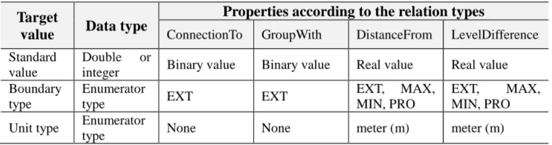
Table 3-6 Data type and properties of the target value according to the relation type Target
value Data type
Properties according to the relation types
ConnectionTo GroupWith DistanceFrom LevelDifference Standard
value
Double or
integer Binary value Binary value Real value Real value Boundary
type
Enumerator
type EXT EXT EXT, MAX,
MIN, PRO
EXT, MAX, MIN, PRO
Unit type Enumerator
type None None meter (m) meter (m)
As explained earlier, the relation information includes four relation types;
“ConnectionTo”, “GroupWith”, “DistanceFrom”, and “LevelDifference”. The
“ConnectionTo” type represents physical connection of two objects; the target object and the subjective object. If the two objects are arranged longitudinally next to each other, the value for the relation is assigned as “1”. If two objects are not arranged, then the value is assigned as “0”. Using the “ConnectioTo” type, the physical connectivity of two objects along the longitudinal direction of the offshore plant can be expressed by experts. The “GroupWith” type represents symmetric connection of two objects. If the two objects are arranged symmetrically and transversely (port and starboard side), the value for the relation is assigned as “1”. If two objects are not arranged, then the value is assigned as “0”. Using the “GroupWith” type, the symmetrical connectivity of two objects along the transverse direction of the offshore plant can be expressed by experts. The “DistanceFrom” type represents physical distance between the target object and the subjective object. The shortest route from the target object to the subjective object is selected to calculate the value for the relation; the distance between two objects. Thus, the minimum distance between the target object and the subjective object can be calculated by using
“DistanceFrom” keyword. The “LevelDifference” type represents the difference of
vertical distance between the target object and the subjective object. Using the
“LevelDifference” type, a certain criteria for the vertical distance between two objects can be expressed by the experts.
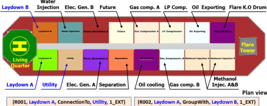
An example of the relation information of using the “ConnectionTo” and
“GroupWith” types is shown in Figure 3-5. In the arrangement design of the offshore plant topside, the “Laydown A” module and the “Utility” module are arranged longitudinally next to each other. This knowledge can be represented as the relation information: (R001, Laydown A, ConnectionTo, Utility, 1_EXT). In addition, the
“Laydown A” and “Laydown B” modules are arranged symmetrically; port and starboard side. And thus this knowledge can be represented as the relation information: (R002, Laydown A, GroupWith, Laydown B, 1_EXT).
Figure 3-5 Example of the relation information of using the "GroupWith" and
“ConnectionTo” type
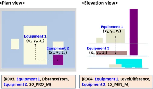
An example of the relation information of using the “DistanceFrom” and
“LevelDifference” types is represented in Figure 3-6. If a certain equipment (“Equipment 1”) is proposed to be arranged from another equipment (“Equipment
2, 20_PRO_M). When applying this rule to the given alternative for the arrangement design, the distance between the “Equipment 1” and “Equipment 2” can be calculated from their rectilinear distance as |x1-x2|+|y1-y2|+|z1-z2|. In addition, if a certain equipment (“Equipment 1”) needs to be arranged vertically from another equipment (“Equipment 3”) with a minimum distance of 15m, it can be expressed by defining the relation information using the “LevelDifference” keyword: (R004, Equipment 1, LevelDifference, Equipment 3, 15_MIN_M). At this time, the vertical distance between the “Equipment 1” and “Equipment 3” can be calculated as (z1-z3).
Figure 3-6 Example of the relation information of using the “DistanceFrom” and
“LevelDifference”
3.3. Arrangement evaluation
The body of the knowledge of experts about the arrangement design of an offshore plant topside is expressed with two lists: the object and relation lists. Based on these lists, rules are made, and arrangement design alternatives are evaluated based on such rules. As described in prior sections, specific requirements on objects to be arranged to an offshore plant topside can be expressed by the object and relation information. The requirements on the location, orientation, COG position of the objects can be defined by the object information. The requirements on the connection and distance between the objects can be defined by the relation information. The object and relation information are converted a set of IF-THEN rules, which are then used to evaluate the feasibility of the alternatives. The object or relation information can be defined differently from one another using some boundary types for the target value, such as “EXT” for exact value, “MAX” for maximum value, “MIN” for minimum value, and “PRO” for proposed value. As for the boundary type “EXT,” if it is used, the rule is “the value of the object should be exactly the same as the target value.” Therefore, if the value of the object is the same as the target value, the index for this rule is evaluated as “100” points, and if it is different, the index becomes “0”
point. If the boundary type “MAX” is used for the target value of a certain object information, the rule is “the value of the object should be lower than the maximum value.” Therefore, if the value of the object is lower than the maximum value, the feasibility index for this rule is evaluated as “100” points, and if the value is higher than the maximum value, the feasibility index for this rule is evaluated as “0” point.
The boundary type “MIN” is similar to “MAX.” If the boundary type “PRO” is used, the linear-fit function evaluates the feasibility index of the object or relation
function is. More details can be found in the previous study of the authors (Kim et al., 2015).
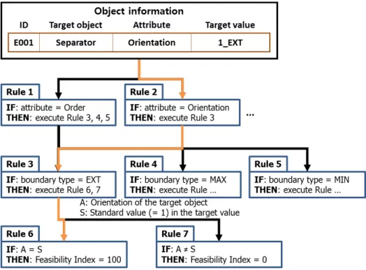
The example described in Figure 3-2 can be converted to the set of rules of IF- THEN phrases, as shown in Figure 3-7. As shown in this figure, an appropriate rule (“Rule 2” in this example) which was already made and corresponds to the attribute in the object information is selected and executed. Again, an appropriate rule (“Rule 3”) which was already made and corresponds to the boundary type is selected and executed. With the target object and the target value, appropriate rules (“Rule 6” and
“Rule 7”) are automatically selected and converted, the rules are executed to calculate the feasibility index of this object information (ID of “E001”) for the given design alternative. At this time, the feasibility index can be calculated by comparing the orientation of the target object (“Separator”) for the given design alternative and the standard value (=1, the target object must have exact orientation along the longitudinal direction of the offshore plant) in the target value.
Figure 3-7 Example of the converting procedure of the object information to rules
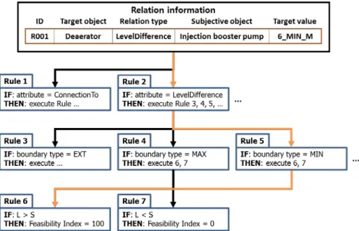
Similarly, the example described in Figure 3-4 can also be converted to the set of rules of IF-THEN phrases, as shown in Figure 3-8. As shown in this figure, an appropriate rule (“Rule 2” in this example) which was already made and corresponds to the relation type in the relation information is selected and executed. Again, an appropriate rule (“Rule 5”) which was already made and corresponds to the boundary type is selected and executed. With the target object, the subjective object, and the target value, appropriate rules (“Rule 6” and “Rule 7”) are automatically selected and converted, the rules are executed to calculate the feasibility index of this relation information (ID of “R001”) for the given design alternative. At this time, the difference of vertical distance between the target object (“Deaerator”) and the
“GroupWith”, and “DistanceFrom”, a suitable module for the connection or distance calculation can be used.
The object list and the relation list are, as mentioned above, automatically converted to the set of rules of IF-THEN” phrases. Then, according to the boundary type, the relation type, and the attribute in the object and relation information, an appropriate procedure is performed to calculate the feasibility indices for the object and the relation information included in the object and the relation lists.
Figure 3-8 Example of the converting procedure for the relation information to rules
3.4. Weight factor for the rules
A specific rule can be more important than other rules. Also appropriate evaluation method should be provided if different rules are conflicted with each other.
To resolve these cases, weight factor is adopted to express the importance of the rule.
Considering the weight factor, feasibility index of the rule “k” is calculated as shown in equation 1.
𝐹𝐹𝐹𝐹𝐹𝐹𝐹𝐹𝐹𝐹𝐹𝐹𝐹𝐹𝐹𝐹𝐹𝐹𝐹𝐹 𝐼𝐼𝐼𝐼𝐼𝐼𝐹𝐹𝐼𝐼𝑘𝑘 = 𝑊𝑊𝑘𝑘×𝑅𝑅𝑘𝑘 (1)
“Wk” is the weight factor, and “Rk” is the evaluation score of the rule “k”.
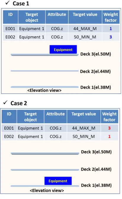
Example is shown in Figure 3-9. It is assume that there are two object information for the position of COG.z of equipment 1. “E001” makes the “Equipment 1” to be arranged in “Deck 1” by defining the COG.z as maximum 44 meters. However,
“E002” makes the “Equipment 1” to be arranged in “Deck 3” by defining the COG.z as minimum 50 meters.
In case 1, the weight factor of “E001” is set as 1, and the weight factor of “E002”
is set as 3. Evaluation scores of the each rule are same. Since the weight factor of the
“E002” is higher than “E001”, “Equipment 1” will be arranged in “Deck 3” by satisfying the object information of “E002” rather than satisfying the object information of “E001”, as shown in the case 1 of Figure 3-9.
By contrast, the weight factor of “E001” is set as 3, and the weight factor of “E002”
is set as 1 in case 2. Since the weight factor of the “E001” is higher than “E003”,
“Equipment 1” will be arranged in “Deck 1” by satisfying the object information of
Figure 3-9 Example: effects of the weight factor
Arrangement optimization model (AOM) for the arrangement design of an offshore plant topside
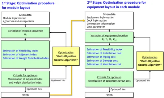
This section describes an optimization method for the arrangement design of an offshore plant topside. As mentioned earlier, the arrangement design of the FPSO topside can be divided into two stages (Ku et al., 2014). Thus, in this study, the arrangement method of the FPSO topside, was formulated as two stages optimization problem. Configuration of the optimization procedure is shown in Figure 4-1. First stage is the module arrangement. In this stage, the arrangement sequence of the modules is determined by minimizing the adjacency index and weight distribution index against y axis. Second stage is the equipment arrangement in each module. In this stage, the optimal location of the equipment such as the x, y coordinate, orientation information and installed deck information is determined by minimizing the installation cost, piping cost, damage cost and ventilation cost. Several constraints are used for equipment arrangement. Firstly, duplication-free constraints are used. Secondly, orientation constraints are used. According to the binary variable for equipment orientation, length and width of the equipment are determined. Thirdly, non-overlapping constraints are used. In these constraint, operating spaces around each equipment are considered. Fourthly, boundary constraints are used to arrange the equipment inside the deck area. Passages around the perimeter of the deck are reflected in these constraints. Fifthly, passage constraints are used. It sets the limits of location of internal passage.
Comparing the defined rule and arrangement information, AEM returns the feasibility index. In both stages, the feasibility index from the expert system is used as one of the objective functions. Genetic algorithm was used for the optimization.
Figure 4-1 Configuration of the two stages optimization problem for the arrangement design of the FPSO topside
4.1. Optimization of the module arrangement
First stage is the module arrangement. Environmental condition such as the prevailing wind direction, process flow, riser location from the subsea and others should be considered. For example, as mentioned in section 1.1, the living quarter should be arranged upwind considering the prevailing wind direction. Flare tower should be arranged as far as possible to the living quarter. And utility areas such as the water injection module, utility module etc. should be arranged between the living quarter and hydro carbon processing modules to serve as a barrier when fire or explosion is occurred. In this study, the module arrangement design is formulated as optimization problem.
4.1.1. Input data
Input data for the module arrangement is summarized in Table 4-1. Total number of the module in FPSO topside and id of the each module are needed. Module information such as width, length and weight of the module are also required. Lastly, adjacency coefficient between each module is required. Adjacency coefficient is the constant number which quantitatively represents the degree of the closeness between each module. It can be calculated from the antagonism and affinities as shown in equation 2.
( )
ij engineering manning
q = Affinity +Affinity −Antagonism (2)
In equation 1, antagonism is the characteristics which preclude a module being
is the engineering affinity, and another is the manning affinity. Engineering affinity is related with the process flow. If one module is connected to another specific module by the process flow, it is advantageous to locate these function groups close to each other. Manning affinity is related with the movement of staff or material between the modules. If it is anticipated to have frequent movement of staff or material between the specific function groups, it is advantageous to located these function groups close to each other.
Table 4-1 Input data for the module arrangement Input data
Total module number and ID of each module
Width and length of the module di, li
Module weight wi
Adjacency coefficient between each module qij
4.1.2. Design variables
In this stage, design variable is the arrangement sequence of the module arrangement. The locations of the each module can be represented as an array of the module “id” (encoding). After optimization, the array is converted to the module arrangement (decoding).
Figure 4-2 Representation of the positions of each module
4.1.3. Objective functions
Objective functions for the optimization of the module arrangement are summarized in Table 4-2. First objective function of this stage is to maximize the feasibility index from the expert system. Feasibility index is returned from the expert system based on the defined object and relation information.
Second objective function is to minimize the adjacency index. The adjacency
function group being safely located near another specific function group mutually protected like fire or blast barriers. Affinities are the characteristics which make it particularly advantageous to located one function group close to another specific function group. There are two affinities. First is the engineering affinity. It is related with