CAD-CAM assisted flapless 수술법으로 식립된 임플란트의 안정성 : 기초연구
강릉원주대학교 치과대학 치과보철학교실 오사카치과대학교 유치보철교합학강좌
박찬진․김대곤․조리라․Kosuke Kashiwagi․Takayoshi Kawazoe․Masahiro Tanaka
CAD-CAM기법과 CT의 도움으로 무판막임플란트 치료술식이 가능하게 되었다. 본 연구의 목적은 1년간 전향적 연구를 통해 이러한 술식의 신뢰성을 검토하고자 하였다. 하악무치악상태의 연속적인 환자 12명이 포함되었다.
71개의 임플란트가 이공사이에 NobelGuide
TM법을 이용하여 식립되었고 환자는 정해진 주기에 따라 검사되었다.
한 개의 임플란트가 조기실패하였으며 나머지는 만족할 만한 기능을 보였다. 연구기간 중 평균적인 변연골흡수량 은 중앙부(0.3±0.1 mm), 견치부(0.5±0.1 mm), 원심부(0.7±0.2 mm)였으며 임플란트 안정성 수치의 변화량은 중앙부 (-1.05±2.76 mm), 견치부(-0.85±2.59 mm), 원심부(-1.27±2.18 mm)를 나타내었고 위치간 통계학적인 차이는 없었다 (P>.05). 본 전향적인 기초조사연구에서 CAD-CAM기반의 무판막임플란트 치료술식은 하악무치악환자에게 신뢰 성 있는 술식이 될 수 있을 것으로 사료되었다.
주요어: 무판막임플란트수술, CAD-CAM기법, 하악무치악, 변연골흡수량, ISQ 변화량
(
구강회복응용과학지 2011:27(4):405~413)
서 론
전통적으로 임플란트 식립술식은 판막거상을 필요로 하였다. 최근에 최소한의 침습적인 방법 을 통해 기능, 심미와 편안함을 가능하게 해주는 기법에 관심이 증가되고 있다. 이러한 술식들은 많은 임상가들에게 옹호되어져 가고 있는 추세 이며 전통적인 수술 기법과 비교하여 무판막술 식(flapless surgery)이 여러 장점을 갖게 되었다
1-10)
. 가능한 한 최선의 결과를 얻기 위하여 비교
적 정확하게 제작된 수술가이드를 사용하고 미
교신저자:
박찬진
강원도 강릉시 죽헌길 7, 강릉원주대학교 치과대학, 210-702
Tel: +82-33-640-3153, Fax: +82-33-640-3113, E-mail: [email protected]
원고접수일: 2011년 10월 20일, 원고수정일: 2011년 11월 16일, 원고채택일: 2011년 12월 25일
리 제작된 임시보철물을 사용한 기법이 제안되었
다
5,11). 출혈을 최소화하고 술후 동통을 줄이며 봉
합의 과정이 필요없어 수술 시간을 단축시키는 등 환자와 술자에 많은 편의를 제공해 주는 장점 이 있다. 발치와에 적용하는 경우도 있으며
12), 부 분 혹은 완전 무치악에 적용이 확대되었다
5).
많은 장점에도 불구하고 무판막임플란트 수술
기법은 일반적으로 blind 과정이기에 컴퓨터를
이용한 가이드를 제작하고 이를 수술에 적용하
는 방법이 개발되어 사용되어 지고 있다
6,9,13). 실
제로 CT스캔을 통해 삼차원적인 영상을 얻은 후
이를 평가에 이용하고 임플란트 식립위치를 다 각도로 평가하여 선정하고 결정함으로써 예측가 능한 수술이 가능해지고 환자의 골조건과 골질 을 감안한 생역학적인 위치에 임플란트 위치를 결정 가능케 함으로써 한층 정교화된 술식이 가 능하게 되었다
6,14). 컴퓨터를 이용한 이러한 CAD-CAM 지원 수술가이드를 여러 임상가들이 선호하고 사용되고 있음에도 불구하고 여전히 여기에 대한 데이터가 부족한 실정이다. 따라서 본 연구는 전향적인 연구를 통해 1년간의 추적조 사로 가능성을 타진하고 추후 장기적 데이터를 위한 기초자료로 사용하기 위하여 수행되었다.
연구재료 및 방법 1. 대상 환자 및 임플란트
2008년 4월부터 2009년 9월까지 총 12명의 하 악완전무치악환자가 연속적으로 본 연구에 포함 되었다. 평균연령은 55.7세(42-69세, 남자 5명, 여 자 7명)로 비흡연자이고 전신적인 건강이 양호 하며 골증강술이 필요없는 환자를 대상으로 하 였다. 전신병력이 있거나 골유도가 필요한 경우 등은 제외하였고 모든 환자는 술전 상세한 설명 과 함께 동의서의 내용을 숙지하고 본 연구에 참
1
2
3-1 3-2
4 5 1
2
3-1 3-2
4
5 1
2 3
4 1 5
2 3
4 5
Fig. 1. Implantation sites on anterior mandible according to arch shape.
Specific zones are practically categorized with 1) center zone : 3-1, 3-2(left), 3(right), 2) canine zone : 2, 4, 3) distal zone : 1, 5.
여하였다. 이공간의 거리는 환자마다 상이하였 으므로 5개 혹은 6개의 4.3 x 13 mm 사양을 갖는 NobelReplace
TM(NobelReplace TaperedGroovy;
NobelBiocare, Gothenburg, Sweden)가 식립되었으 며 이는 중앙부, 견치부, 원심부 등 3 영역으로 나누었다(Fig. 1).
2. 치료 프로토콜
1) 방사선 촬영 및 수술가이드 준비
방사선 촬영을 위해 환자의 심미, 발음, 적정 교합수직고경을 평가하고 임시 총의치를 제작하 고 환자의 적정 중심위와 수직고경에서 교합관 계기록을 실리콘인기재(Regisil Rigid; Densply Intl, Milford,USA)를 이용하여 채득하였다(Fig.
2). 총의치의 순,협측 및 설측 연마면에 최소한 9 곳 이상에 2 mm의 구멍을 형성하고 gutta percha(Temporary stopping; GC corporation, Tokyo, Japan)로 충전하여 방사선 촬영시 지표로 사용하 고자 하였다. double scan 기법을 이용한 NobelGuide
TM(NobelBiocare, Gothenburg, Sweden) 시스템을 이용하고자 CT 스캔을 행하고 DICOM 파일을 얻기 위해
16)환자에 의치를 장착시키고 촬영한 후 의치만 따로 CT촬영하였다. 얻어진 CT결과로부터 DICOM 파일을 얻었으며 이를
Fig. 2. New temporary dentures and interocclusal
record.
Fig. 3. Three dimensional image-based treatment planning software(Procera software;
Nobel Biocare AB). Using the program, 6 regular platform implants and 3 horizontal anchor pins were planned.
Procera software (ProceraSoftware; NobelBiocare, Gothenburg, Sweden)를 이용하여 3차원영상을 얻 었다. 얻어진 골의 3차원영상을 의치의 영상과 방사선지표를 통해 가상공간상에서 조합함으로 써 최종적인 영상을 얻었으며, 이공의 존재와 경 로를 추적하고 양 이공간의 공간사이에 임플란 트를 5개 혹은 6개 식립하기 위한 위치를 결정하 고 식립깊이와 각도를 조절하였다(Fig. 3). 임플 란트 고정체는 모두 NobelReplace
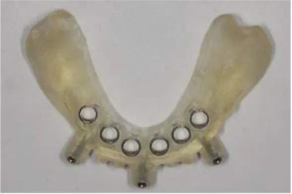
TM로 선택하였 으며 3개의 고정핀의 위치도 확정한 후 프로세 라 밀링센터에 전송하여 1주일 후 설계대로 제 작된 stereolithographic 수술가이드를 얻었다(Fig.
4). 임시 고정성 보철물이 수술가이드를 이용하 여 제작되었고(Fig. 5) 수술가이드를 환자구강내 에 위치시킬 수 있도록 모형상에 악간관계기록 을 얻었다.
2) 수술 및 보철과정
무판막임플란트 수술이 국소마취하에 수행되 었다. 수술가이드를 미리 제작한 악간관계기록
Fig. 4. Stereolithographic surgical template.
Fig. 5. Prefabricated fixed provisional restoration.
The prosthesis had only one temporary cylinder connection for others’ direct connection intraorally.
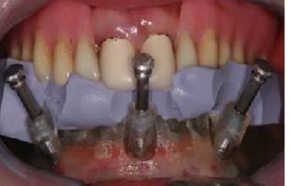
을 이용하여 장착하고 3개의 고정핀을 이용하여
구강내에 고정하였다(Fig. 6). 드릴가이드를 이용
하여 순차적인 골형성을 한 후 최종적인 고정체
를 식립하였다(Fig. 7). 미리 선정된 MUA 지대주
(multi-unit abutment;Nobel Biocare, Gothenburg,
Sweden)를 연결하고 임시 지대주를 장착한 후
술전에 제작해 둔 임시 고정성 의치를 구강내에
서 소량의 레진(Jet, Lang dental, Wheeling,USA)
을 이용하여 임시 지대주와 직접적인 연결방법
을 통해 최종적인 마무리를 하여 장착하였다
Fig. 6. Mandibular surgical template in situ. The surgical template was positioned with the centric relation interocclusal record (prefabricated on the semiadjustable articulator).
Fig. 7. Installed implants using surgical template.
Fig. 8. Occlusal view of temporary prostheses.
(Fig. 8). 교합조정을 시행하여 적절한 교합을 부 여하였으며 캔틸레버부위의 어떠한 측방교합접 촉은 부여하지 않았다.
3) 환자 검진 주기
술후 초기에는 환자에게 유동식을 권고했으며 술후 2일, 1주일 후 발생할 수 있는 초기 합병증 을 관찰하고자 내원토록 하였다. 이후 1, 3, 6, 12 개월 간격의 재내원을 지시하여 합병증을 조사 하고 측정을 시행하였다. 최종보철물은 식립 6개 월 이내에 모두 제작되었다.
3. 변연골 수준의 측정
환자 내원시 평행 촬영법을 위한 필름유지기구 (Sensor holder, Biomedisys, Korea)와 구내방사선 촬영기(CDX2000U, Biomedisys, Korea)를 이용하 여 치근단 방사선사진을 촬영하고 각 나사산 내 에 해당하는 영역은 한 사람이 지정하였다. 영역 내 계조도를 보정하고자 포토샵 프로그램(Adobe photoshop 9.0, Adobe, USA)을 이용하여 영상 처 리를 하고 변연골과 임플란트의 첫 번째 접촉부 를 고정체의 최상부를 기준점으로 하여 변연골 수준을 측정하였다. 위 과정을 두번 반복하여 그 평균을 구하였다. 5개 혹은 6개의 임플란트가 식 립되었으므로 이를 각각 중앙부, 견치부, 원심부 등 3부분으로 나누어 그 평균을 산출하였다.
4. 임플란트 안정지수 변화량 측정
Osstell
TM(Integration Diagnostic Ltd., Gothenburg, Sweden)을 사용하였으며 식립시 측정값을 기준 으로 내원간 변화량을 구하였다.
5. 통계 분석
95% 신뢰수준에서 임플란트 위치간 시간에
따른 ISQ 수치 및 변연 골 수준의 변화 양상 비
교는 반복측정이 있는 일원분산분석을 시행하였
다(SPSS 19.0, SPSS Inc., Chicago, USA).
complicatons (time) failure cantilever fracture resin tooth fracture
0 – 1 month 1 1 0
1 – 3 month 0 3 1
3 – 6 month 0 0 2
total 1 4 3
Table I. Complications of implants and prosthesis during observation period
결 과
1. 임플란트 실패 및 합병증(Table I) 식립된 임플란트 중 1개의 임플란트가 1달 재 내원 검진시 동요가 있어 제거되었으며 새로운 임플란트로 교체되었다. 4명의 임플란트 환자에 서 캔틸레버부와 원심임플란트 고정체 사이에 파절선이 관찰되었고 이는 즉시 수리되었다. 나 사풀림 등의 합병증은 발생하지 않았으나 레진 치아 탈락이 3명에서 관찰되었다.
2. 변연골 흡수량(Fig. 9)
평균적인 1년간의 변연골흡수량은 중앙부(0.3
±0.1 mm), 견치부(0.5±0.1 mm), 원심부(0.7±0.2 mm)였으며 시간에 따른 위치간 통계학적인 차 이는 없었다(P>.05).
Fig. 9. Average marginal bone loss changes of each zone during 1 year.
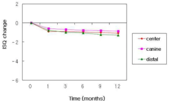
3. 임플란트 안정지수 변화량(Fig. 10) 임플란트 안정성 수치의 1년간 변화량은 중앙 부(-1.05±2.76 mm), 견치부(-0.85±2.59 mm), 원심 부(-1.27±2.18 mm)를 나타내었고 원심부의 경우 약간의 감소경향을 보였으나 시간에 따른 위치 간 통계학적인 차이는 없었다(P>.05).
고 찰
전통적인 수술법에 비교하여 무판막 수술법은 술후 출혈 및 불편감 등의 합병증을 줄이는데 효 과적이다. 또한 수술시간의 감소와 치유기간을 개선하는데도 도움이 된다
6,9,14,19,20). 또한 즉시하 중 개념의 보철물은 환자의 생활개선에 도움을 준다. 그러나 임플란트 식립시 중요한 초기고정 성의 측면에서는 예지성이 판막 수술법에 비해 떨어질 수 있고 특히 캔틸레버 형식의 보철물을
Fig. 10. Average ISQ value changes of each
zone during 1 year.
위한 설계에서 원심측에 위치한 고정체에 가해 지는 응력은 다른 위치의 고정체에 비해 상대적 으로 커질 수 있다
21,22). 본 연구에서 실패한 한 개의 임플란트는 좌측 최후방 원심부에 위치한 고정체였으며 제거 후 판막 수술법에 의해 새로 운 고정체의 초기 고정력을 확보하고 기존 임시 고정성의치에 연결하여 교합조정함으로써 별다 른 합병증 없이 회복되었다. 12명의 환자에서 대 합치의 조건이 상악총의치인 경우가 6명이었는 데, 임시고정성의치의 캔틸레버부 파절선은 상 악총의치 장착자 2명, 유리단 상악국소의치 장착 자 1명, 유치악자 1명이었다. McAlarney 등
23)은 55개의 임상 증례 자료를 컴퓨터에 입력하여 Skalak 모형으로 기계적 과하중(mechanical overload)를 계산하였으며 그 결과 캔틸레버 부위 에 가해지는 교합력은 최후방 임플란트에 2~3 배의 하중을 발생시켰으며 5~6개의 임플란트를 식립한 경우 최후방 임플란트의 질이 더 중요하 다고 하였다. 그러나 임상적으로 대합치의 조건 에 따른 파절선의 발생은 예측하기 어려우며 교 합관계, 환자의 습관, 수복물의 두께 등 복합적 으로 발생한다고 생각된다. 레진치아 탈락의 경 우에도 이와 같은 맥락에서 생각할 수 있으며 본 연구에서 발생하는 합병증들은 조절 가능하였 다.
변연골 흡수 양상의 시간경과에 따른 변화에 있어서 임플란트 식립 첫 해가 가장 활발한 변화 기간임에도 불구하고
24)본 연구에서는 통계학적 으로 유의한 부위별 차이를 보여주질 못했다. 특 히, 보철물의 파절선이 일어나는 경우와 연관지 어 생각해 볼 때, 상대적으로 위험한 상황이라 생각할 수 있다 하더라도 파절에 의한 응력의 소 실과 수리시 교합관계의 조정 등을 통해 해소되 는 것으로 유추할 수 있다. 반대로 연구에 포함 된 인구수가 상대적으로 작고 단기간의 추적조 사이므로 뚜렷한 결과를 얻기 어려울 수도 있다.
방법상의 문제에 있어서 각 부위의 방사선사진 측정결과를 해석할 때 고정체 하나당 근심과 원 심의 골수준이 다르고 이를 평균적인 수치로 나
타내는 것은 해석에 있어서 무리가 있다고 생각 할 수 있으나 그 변화량이 크지 않으므로 편의상 평균치를 사용하였다. 평행촬영법을 최대한 적 용하려고 노력하였으나 고정체 각각에 대한 개 별적인 유지장치를 제작하는 경우
25,26)에 비해 정 확성이 떨어질 수 밖에 없는 한계도 있다고 사료 된다.
임플란트 안정지수의 변화량 측정은 임상적으 로 오래전부터 널리 사용되는 방법으로
27-30)초기 고정력과 함께 골치유기간의 치유능에 의한 골- 임플란트계면의 견고도에 의해 영향을 받는다.
골질이 우수한 이공사이 부위에 있어서는 초기 식립시보다 감소의 경향을 보이기도 하며 변연 골 수준에 의해서 영향을 받으므로 변화되는 골 수준에 어느 정도 변화량을 보여주리라 기대할 수 있다. 하지만, 본 연구에서 원심부위의 평균 적인 변화량이 다른 부위에 비해 상대적으로 낮 은 수치를 보여주는 경향이 있었으나 통계적으 로 유의한 차이를 보이지는 않았다. 이는 치유과 정에 있어서 안정지수의 변화량이 증가되거나 감소되는 패턴, 변화가 거의 없이 유지되는 패턴 등이 복합적으로 일어나 경향성을 보이기는 어 렵다는 점과 골변화량이 거의 없었다는 점으로 유추할 수 있다.
보철수복 방법에 있어서 본 연구에서는 최종
보철물을 미리 제작하지 않고 임시보철물을 미
리 제작하여 구강내 연결하는 방법을 사용하였
는데, 이는 임플란트 식립시 발생하는 최종고정
체의 위치적인 오차를 감안한 것이다. Schneider
등
31)은 컴퓨터를 이용하여 설계된 수술가이드를
사용한 임플란트 수술의 위치적 오차에 관한 체
계적인 논문검토에서 식립 후 고정체의 최상부
에서 1.07 mm, 고정체 하부에서 1.63 mm의 측방
오차를 보이고 0.43 mm의 수직적 오차와 5.73도
의 수직축각 변위를 보고하였다. CAD-CAM기법
을 이용한 무판막임플란트 식립술식에서 발생할
수 있는 이러한 오차를 감안한다면 최종보철물
을 미리 제작하는 Teeth-in-an-Hour Concept
TM(NobelBiocare AB, Gothenburg, Sweden)술식은 일
반화하여 준용하기에는 다소 어려움이 있을 것 으로 사료된다.
결 론
본 연구의 한계내에서 CAD-CAM기법을 이용 한 무판막 수술법을 하악무치악에 적용하는 것 은 몇몇 연구들에서 언급했듯이 가능하지만 장 기적인 추적조사와 함께 보철물의 디자인에 따 른 고려도 필요하리라 사료된다.
연구비 지원 및 사의
이 논문은 2011년도 강릉원주대학교 장기해외 파견 연구지원(관리번호 2011-0033)에 의하여 수 행되었음
참 고 문 헌
1. Becker W, Goldstein M, Becker BE. Minimally invasive flapless implant surgery: A prospective multicenter study. Clin Implant Dent Relat Res 2005;7:1.
2. Hahn J: Single-stage, immediate loading, and flapless surgery. J Oral Implantol 2000;26:193.
3. Kan JYK, Rungcharassaeng K, Ojano M. Flapless anterior implant surgery: A surgical and prostho- dontic rationale. Pract Periodont Aesthet Dent 2000;12:467.
4. Rocci A, Martignoni M, Gottlow J. Immediate loading in the maxilla using flapless surgery, implants placed in predetermined positions, and prefabricated provisional restorations: A retrospective 3-year clinical study. Clin Implant Dent Relat Res 2003;5:29.
5. Rocci A, Martignoni M, Gottlow J. Immediate loading of Brånemark System TiUnite and machined-surface implants in the posterior mandible:
A randomized open-ended clinical trial. Clin Implant Dent Relat Res 2003;5:57.
6. Azari A, Nikzad S, Kabiri A. Using computer-guided
implantology in flapless implant surgery of a maxilla:
A clinical report. J Oral Rehabil 2008;35:690.
7. Rocci A, Gottlow J. Esthetic outcome of immediately loaded scalloped implants placed in extraction sites using flapless surgery. A 6-month report of 4 cases.
Appl Osseointegration Res 2004;4:55.
8. Wendelhag I, van Steenberghe D, Blombörk U.
Immediate function in edentulous maxillae with flapless surgery including a 3-D CT-scan based treatment planning procedure. Clin Oral Implants Res 2004;15:1.
9. Azari A, Nikzad S. Flapless implant surgery: Review of the literature and report of 2 cases with computer-guided surgical approach. J Oral Maxillofac Surg 2008;66:1015.
10. Marchack CB. An immediately loaded CAD/CAM- guided definitive prosthesis: A clinical report. J Prosthet Dent 2005;93:8.
11. Campelo LD, Camara JR. Flapless implant surgery: A 10-year clinical retrospective analysis. Int J Oral Maxillofac Implants 2002;17:271.
12. Schiroli G. Immediate tooth extraction, placement of a Tapered Screw-Vent implant, and provisionalization in the esthetic zone: A case report. Implant Dent 2003;12:123.
13. Dula K, Mini R, van der Stelt P. The radiographic assessment of implant patients: Decision-making criteria. Int J Oral Maxillofac Implants 2001;16:80.
14. Sclar AG. Guidelines for flapless surgery. J Oral Maxillofac Surg 2007;65:20.
15. Ganz SD. Presurgical planning with CT-derived fabrication of surgical guides. J Oral Maxillofac Surg 2005;63:59
16. van Steenberghe D, Glauser R, Blomb U. A computed tomographic scan-derived customized surgical template and fixed prosthesis for flapless surgery and immediate loading of implants in fully edentulous maxillae. A prospective multicenter study.
Clin Implant Dent Relat Res 2005;7:111.
17. Wittwer G, Adeyemo WL, Wagner A. Computer-
guided flapless placement and immediate loading of
four conical screw-type implants in the edentulous
mandible. Clin Implant Dent Relat Res 2007;18:534.
18. Rosenfeld AA, Mandelaris GA, Tardieu PB.
Prosthetically directed implant placement using computer software to ensure precise placement and predictable prosthetic outcomes. Part 1: Diagnostics, imaging, and collaborative accountability. Int J Periodontics Restorative Dent 2006;26:215.
19. Jeong SM, Choi BH, Li J. Flapless implant surgery:
An experimental study. Oral Surg Oral Med Oral Pathol Oral Radiol Endod 2007;104:24.
20. Fortin T, Bosson JL, Isidori M, et al: Effect of flapless surgery on pain experienced in implant placement using an image-guided system. Int J Oral Maxillofac Implants 2006;21:298.
21. Sertgöz A, Güvener S. Finite element analysis of the effect of can- tilever and implant length on stress distribution in an implant- supported fixed prosthesis.
J Prosthet Dent 1997;76:165-9.
22. Romeo E, Lops D, Margutti E, Ghisolfi M, Chiapasco M, Vogel G. Implant-supported fixed cantilever prostheses in partially edentulous arches. A seven-year prospective study. Clin Oral Impl Res 2003;14: 303-11.
23. McAlarney ME, Sc DE, Stavropoulos DN. Theoretical cantilever lengths versus clinical variables in fifty-five clinical cases. J Prosthet Dent 2000;83:332-43.
24. Lindquist LW, Carlsson GE, Jemt T. A prospective 15-year follow- up study of mandibular fixed prostheses supported by osseointegrat ed implants.
Clinical results and marginal bone loss. Clin Oral Impl Res 1996;7:329-36.
25. Jeffcoat MK, Reddy MS, Webber RL, Williams RC, Ruttimann UE. Extraoral control of geometry for digital subtraction radiography. J Periodont Res 1987;22:396-402.
26. Meijer HJA, Steen WHA, Bosman F. Standardized radiographs of alveolar crest around implants in the mandible. J Prosthet Dent 1992;68:318-21.
27. O'Sullivan D, Sennerby L, Meredith N.
Measurements comparing the initial stability of fie designs of dental implants. A human cadaver study.
Clin Oral Den Rel Res 2000;2(2):85-92
28. O'Sullivan D, Sennerby L, Meredith N. Influence of implant taper on the primary and secondary stability of osseointegrated titanium implants. Clin Oral Impl Res 2004;15:474-80.
29. Glauser R, Sennerby L, Meredith N, Rée A, Lundgre A, Gottlow J, Hämmerle CHF. Resonance frequency analysis of implant subjected to immediate or early functional occlusal loading. Successful vs failing implants. Clin Oral Impl Res 2004;15:428-34.
30. Huang HM, Chiu CL, Yeh CY, Lin CT, Lin LH, Lee SY. Early detection of implant healing process using resonance frequency analysis. Clin Oral Impl Res 2003;14:437-43.
31. Schneider D, Marquatdt P, Zwahlen M, Jung R. A
systematic review on the accuracy and the clinical
outcome of computerguided template-based implant
dentistry. Clin Oral Impl Res 2009;20:73-86
Implant stability installed with CAD-CAM assisted flapless surgery : A pilot study
Chan-Jin Park, Dae-Gon Kim, Lee-Ra Cho, Kosuke Kashiwagi, Takayoshi Kawazoe, Masahiro Tanaka Department of Prosthodontics and Institute of Oral Science, College of Dentistry, Gangneung-Wonju National University
Department of Fixed Prosthodontics and Occlusion, Osaka Dental University
It was proposed that technologies derived from CAD-CAM and computed tomography may be useful for flapless implant treatment procedures. The aims of this study were to validate the reliability of this concept in a prospective 12-month clinical study. Twelve patients with fully edentulous areas in their mandibles were included in this study. A total of 71 implants were inserted in interforamina regions by use of a CAD/CAM drill template(NobelGuide
TM), specially designed for flapless implant surgery. To assess the degree of pain and discomfort, the patients were examined at 2 days and 1 week after surgery. Patient satisfaction and implant functionality were further evaluated at follow-up intervals of 1, 3, 6, and 12 months postoperatively. One implant failed early in 1 patient. All of the other implants were in a good functional state throughout the study. The mean marginal bone loss after 1 year of follow-up was 0.3 mm (SD, 0.1) at center, 0.5 mm (SD, 0.1) at canine and 0.7 mm (SD, 0.2) at distal fixtures, respectively. Statistically, there was not significant differnces among each sites(P>.05)The mean ISQ change after 1 year of follow-up was –1.05 (SD, 2.76) at center, -0.85 (SD, 2.59) at canine and –1.27 (SD, 2.18) at distal fixtures, respectively. This prospective pilot study showed that the use of CAD/CAM technology and flapless implant surgery may be considered reliable for fully edentulous mandible of patients.
Key words: flapless surgery, CAD-CAM technique, edentulous mandible, marginal bone loss, ISQ change
Correspondence to : Chan-Jin Park
Department of Prosthodontics, College of Dentistry, Gangneung-Wonju National University, 7 Jukheongil, Gangneung city, Gangwon-do, South Korea, 210-702
Tel : +82-33-640-3153, Fax : +82-33-640-3113, E-mail: [email protected]
Received: October 20, 2011, Last Revision: November 16, 2011, Accepted: December 25, 2011