aGraduate Student, Department of Orthodontics, School of Dentistry, Seoul National University.
bDirector, Department of Craniofacial Orthodontics, Childrens’
Hospital of Phildelphia.
cAssociate Professor, Department of Prosthodontics, School of Dentistry, Seoul National University.
dGraduate Student, gAssociate Professor, Department of Ortho- dontics, School of Dentistry, Kyung Hee University.
eClinical Fellow, Department of Restorative Dentistry, School of Dentistry, Kyung Hee University.
fProfessor and Chairman, Department of Dentistry, School of Medicine, Ajou University.
hClinical Associate Professor, Division of Orthodontics, Department of Orofacial Science, University of California SanFrancisco.
Corresponding author:Seong-Hun Kim.
Department of Orthodontics, School of Dentistry, Kyung Hee University, 1 Hoeigi-dong, Dongdaemun-gu, Seoul 130-701, Korea.
+82 2 958 9392; e-mail, [email protected].
Received May 30, 2011; Last Revision September 20, 2011;
Accepted September 21, 2011.
http://dx.doi.org/10.4041/kjod.2011.41.5.354
*Supported by a grant from Kyung Hee University in 2010 (KHU- 20100696).
The effects of different pilot-drilling methods on the mechanical stability of a mini-implant system at placement and removal:
a preliminary study
Il-Sik Cho, MSD,a HyeRan Choo, MSD,b Seong-Kyun Kim, DDS, MSD, PhD,c Yun-Seob Shin, MSD,d Duck-Su Kim, DDS, MSD, PhD,e Seong-Hun Kim, DDS, MSD, PhD,g
Kyu-Rhim Chung, DDS, MSD, PhD,f John C. Huang, DDS, MSD, PhDh
Objective: To investigate the effects of different pilot-drilling methods on the biomechanical stability of self-tapping mini-implant systems at the time of placement in and removal from artificial bone blocks.
Methods: Two types of artificial bone blocks (2-mm and 4-mm, 102-pounds per cubic foot [102-PCF] poly- urethane foam layered over 100-mm, 40-PCF polyurethane foam) were custom-fabricated. Eight mini-im- plants were placed using the conventional motor-driven pilot-drilling method and another 8 mini-implants were placed using a novel manual pilot-drilling method (using a manual drill) within each of the 2-mm and 4-mm layered blocks. The maximum torque values at insertion and removal of the mini-implants were measured, and the total energy was calculated. The data were statistically analyzed using linear regression analysis. Results: The maximum insertion torque was similar regardless of block thickness or pilot-drilling method. Regardless of the pilot-drilling method, the maximum removal torque for the 4-mm block was stat- istically higher than that for the 2-mm block. For a given block, the total energy at both insertion and re- moval of the mini-implant for the manual pilot-drilling method were statistically higher than those for the motor-driven pilot-drilling method. Further, the total energies at removal for the 2-mm block was higher than that for the 4-mm block, but the energies at insertion were not influenced by the type of bone blocks.
Conclusions: During the insertion and removal of mini-implants in artificial bone blocks, the effect of the manual pilot-drilling method on energy usage was similar to that of the conventional, motor-driven pilot-drill- ing method. (Korean J Orthod 2011;41(5):354-360)
Key words: Anchorage, Implant design, Surface treatment, Orthodontic mini-implant
INTRODUCTION
In general, there are 2 types of orthodontic mini- screw systems. One is a self-drilling screw system that often has a single-piece design (i.e. the head portion and the body screw are inseparable). This type of screws are characterized by sharp pitches and a pene- trating screw apex and do not necessarily have os- seointegration-promoting surface treatment.1-3 The other type is a pilot-drilling self-tapping screw system.4-6 This type requires the placement of a pilot hole at the recipient site before engaging the self-tapping screw.
The screws of this system are characterized by blunt
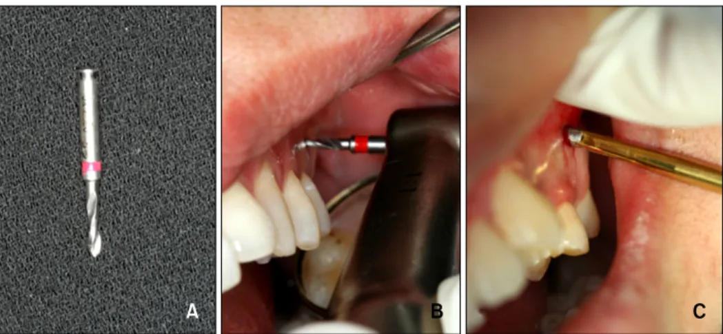
Fig 1. Motor-driven pilot-drilling method. A, A 1.5 mm diameter guide drill; B, pilot drilling using a guide drill; C, C-im- plant placement using a hand driver.
pitches and a screw apex for self-tapping only and of- ten has a two-piece design with a surface treatment that promotes osseointegration during its use in ortho- dontic therapy.6-8
The C-implant system is a pilot-drilling self-tapping screw system. Conventionally, this system requires a motor-driven pilot-drill prior to the insertion of the self-tapping mini-screw body.7,9 The C-implant is a two-piece system by design (i.e. the head and the screw body are separate, giving the flexibility of se- lection of the head component after placing the screw body in the optimal recipient site). The C-implant sys- tem was originally developed as a common orthodontic tool to be placed and utilized by orthodontists. Howev- er, the requirement of a motor-driven pilot-drilling pro- cedure prior to screw placement has always been a sig- nificant technical and psychological burden to the or- thodontists, despite the well-documented long-term sta- bility of the system (utilization of osseointegration- promoting surface treatment) and the inherent proce- dural safety during the self-tapping screw placement (Fig 1).7,10,11 Consequently, orthodontists often have had to refer patients to a periodontist or oral surgeon for C-implant mini-screw placement, with the result that the use of the C-implant system has become un- necessarily cumbersome and less practical for patients and orthodontists.
The trepidation for using the motor-driven pilot-drill- ing procedure further increased after the Centre for
Disease Control and Prevention (CDC) defined any dental protocols requiring a motor-driven pilot-drilling as an oral surgical procedure.12 Therefore, according to CDC standards, the current C-implant placement sys- tem is considered an oral surgical procedure, which is outside the realm of most orthodontic insurance li- ability coverage. On the other hand, the CDC does not categorize a self-drilling mini-screw placement (without a tissue punch incision) as an oral surgical procedure.
Instead, this procedure is considered a common dental procedure equivalent to a local anesthetic injection, making the procedure more amenable to most ortho- dontists.
To abide by the CDC regulation that defines the scope of common dental procedures for orthodontists and to eliminate orthodontists’ fear for performing an
“oral surgery” procedure in an orthodontic clinical set- ting, the authors recently developed a method using a manual drill prior to the insertion of the conventional C-implant mini-screw body (Fig 2). Preliminary clin- ical observations indicate that the novel manual, pi- lot-drilling method will be successful in replacing the conventional motor-driven pilot-drilling procedure with- out compromising the biomechanical stability of the C- implant system at time of placement and removal.
Therefore, the current in vitro study utilized the C-im- plant system as an exemplary pilot-drilling self-tapping orthodontic mini-screw to investigate differences in the biomechanical properties of self-tapping orthodontic
Fig 2. Manual pilot-drilling method using a hand drill. A, A 1.5 mm diameter hand drill; B and C, hand-drilling on the planned positions of a mini-implant placement; D, removal of a hand drill with a counter clockwise rotation; E and F, C-implant placement on the pilot hole; G, after adaption of the head part.
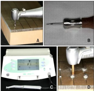
Fig 3. A, Motor-driven pilot-drilling procedure on a artifi- cial bone block; B, a hand drill for manual pilot drilling;
C and D, a surgical engine implant system for the in- sertion of mini-implants and measurement of insertion and removal torques.
mini-screws at placement and removal when using dif- ferent pilot-drilling procedures at placement. The influ- ence of varying densities at the recipient sites was also compared. We hypothesized that the maximum inser- tion and removal torque values, angular momentum, and total energy of C-implant placement and removal with different pilot-drilling methods are not different.
MATERIAL AND METHODS
Two types of artificial bone blocks with different densities were custom-fabricated using polyurethane foams (SawbonesⓇ, Pacific Research Laboratories Inc., Vashon, WA, USA) (Fig 3). Both types of blocks had a base of 100-mm, 40-pounds per cubic foot (PCF) polyurethane foam, but the first type of block was cov- ered with a 2-mm sheet of 102-PCF polyurethane foam and named as 2-mm block. The cover of the second type of block was a 4-mm sheet of 102-PCF polyur- ethane foam, and this block was named as 4-mm block.
Eight C-implants were placed in the 2-mm block by the conventional motor-driven pilot-drilling method (Group A). Another 8 C-implants were placed in the 2-mm block by the novel manual pilot-drilling method using a hand-drill (Group B). The manual drills were 5 mm
long and 1.6 mm in diameter. Further, 8 C-implants were placed in the 4-mm block by the conventional pi- lot-drilling method (Group C), and 8 C-implants were placed in the 4-mm block by the novel pilot-drilling method (Group D). The C-implants used in all the 4
Fig 5. Graph showing the removal torques with respect to the elapsed time. MD, Motor-driven pilot drilling; HD, manual pilot-drilling using a hand drill.
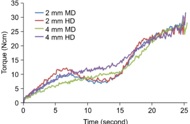
Fig 4. Graph showing the insertion torques with respect to the elapsed time. MD, Motor-driven pilot drilling; HD, manual pilot-drilling using a hand drill.
groups were 6.5 mm long and 1.8 mm in diameter. All C-implants were placed perpendicularly at the block surface. The depth of the pilot-drill was 5 mm. Slight hand pressure was imposed on the pilot drill to make indentations of 2 mm and 4 mm on the 2-mm block and 4-mm block, respectively. Perpendicular hand pres- sure is not necessary up to the 5-mm pilot-drilling depth. Immediately following the designated pilot-drill- ing procedure in each group, a C-implant was engaged in a surgical engine (Elcomed SA200C; W&H, Bur- moos, Austria), and the torque values at the time of C-implant placement and removal were measured in continuous mode. The rotational speed of the engine was fixed at 30 rotations per minute (rpm) (0.5 rota- tions per second), and the maximum torque value pos- sible to measure was set at 50 Nㆍcm both at insertion and removal. The C-implants were placed in the artifi- cial bone block to its maximum length (6.5 mm) and then removed completely in a continuous mode.
In the study, we were interested in the maximum torque values, total energy, and angular momentum at insertion and removal of the C-implants by the 2 pilot- drilling methods. Briefly, the maximum torque value was defined as the highest numeric value measured during the time of C-implant mini-screw placement or removal (in Nㆍcm). The total energy (J) was calcu- lated from the measured torque values, using a Java- based customized computer program, as the total sum of energy used to place or remove the C-implant to or from its maximum length.11,13 The values of total en-
ergy and angular momentum were positively correlated in a mathematical equation, resulting in a similar pat- tern of results.
Statistical analysis
Linear regression analysis was used to compare the effects of the 2 pilot-drilling methods in each artificial bone block. Regardless of inclusion of the 2 interaction factors (type of artificial bone block and pilot-drilling method) in linear analyses, no statistical difference was found for all 4 parameters (maximum insertion torque, total insertion energy, maximum removal torque, and total removal energy). Therefore, a linear model with a higher degree of freedom, without the inclusion of interaction factors, was selected as the final statistical model for the current study.
RESULTS
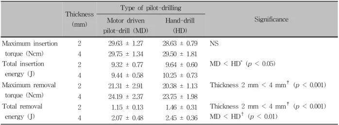
The numeric values of each parameter are shown in Table 1. The value of maximum insertion torque did not show any correlation either with the type of artifi- cial bone block or with the pilot-drilling method (Fig 4). The value of angular momentum of insertion did not show statistically significant correlation with the artificial block quality. However, for the same type of artificial block, the total insertion energy when the manual pilot-drilling method was used was statistically higher than that when the motor-driven pilot drilling
Thickness (mm)
Type of pilot-drilling
Significance Motor driven
pilot-drill (MD)
Hand-drill (HD) Maximum insertion
torque (Ncm)
2 29.63 ± 1.27 28.63 ± 0.79 NS 4 29.75 ± 1.34 29.50 ± 1.81 Total insertion
energy (J)
2 9.32 ± 0.77 9.64 ± 0.60 MD < HD* (p < 0.05) 4 9.44 ± 0.58 10.25 ± 0.73
Maximum removal torque (Ncm)
2 21.31 ± 2.91 20.38 ± 1.13 Thickness 2 mm < 4 mm‡ (p < 0.001) 4 24.19 ± 2.37 23.75 ± 1.98
Total removal energy (J)
2 1.15 ± 0.13 1.46 ± 0.31 Thickness 2 mm < 4 mm‡ (p < 0.001) MD < HD† (p < 0.01)
4 2.07 ± 0.48 2.45 ± 0.36
SLA, Sand blasted with large grit, and acid etched; NS, not significance. *p < 0.05; †p < 0.01; ‡p < 0.001.
Table 1. Maximum torque (Ncm) and total energy (J) employed during insertion and removal for SLA surface-treated orthodontic mini-implants in relation to different thicknesses of sawbone and type of pilot drilling
method was used. As long as the same pilot-drilling method was used, the type of artificial bone block did not influence the total insertion energy.
Regardless of the pilot-drilling methods at insertion, all parameters tested at the removal of the C-implant (maximum removal torque and total removal energy) from the 4-mm block were statistically higher than those tested at removal of C-implant from the 2-mm block (Fig 5). In addition, the total removal energy was statistically higherwhen the manual pilot-drilling method was used than when the motor-driven pilot drilling method was used on the same type of block.
DISCUSSION
The C-implant system is well-known for its uti- lization of an osseointegration-promoting surface treat- ment on the mini-screw body.7,8,14 Despite the concerns of potentially high removal torque values of partially osseointegrated mini-screws (i.e. difficulty in removing the mini-screw when it is no longer needed for the or- thodontic therapy), the advantages of partial osseointe- gration of orthodontic mini-screws have been well- studied and documented.15,16 In brief, the failure rate of mini-screw systems that purely rely on mechanical re- tention during orthodontic therapy is significantly high- er than that for systems utilizing both osseointegration and mechanical retention. Furthermore, partial osseoin-
tegrated mini-screws have higher capability to with- stand high levels of orthodontic force and rotational moments.7,11 One of the common findings in studies of orthodontic mini-screw systems that were stably used for an extended period of orthodontic application is that the surface of those mini-screw systems always showed some degree of osseointegration.8,15,16 To date, no studies have reported any clinical situations where partially osseointegrated orthodontic mini-screws could not be removed by conventional unscrewing methods.
However, the required motor-driven pilot drill to place the C-implant system has been a significant obstacle to an otherwise easy application of C-implant systems by orthodontists.12 Therefore, the current study was ini- tiated to investigate the feasibility of a manual pilot drilling technique using a hand-drill in an effort to re- place the need for motor-driven pilot-drilling.
We found that the maximum insertion torque did not differ statistically for either the type of artificial bone block or the type of pilot-drilling method. The max- imum removal torque for removal from the 4-mm block was statistically higher than that for removal from the 2-mm block, but this parameter did not sig- nificantly differ for the type of pilot-drilling method used at insertion. For the same type of block, the total energy at both insertion and removal of the C-implant system when the manual pilot-drilling method was used were statistically higher than when the motor-
driven pilot-drilling method was used. The total re- moval energy was higher for the 4-mm block than for the 2-mm block, but the total insertion energy was not influenced by the type of block.
The increased values of total energy when the man- ual pilot-drilling method was used can be explained by the fact that manual pilot drilling eliminates the neg- ative effect of the operational tremor of high rpm on pilot-hole formation. The more closely adaptable pilot- hole made by manual pilot drilling, therefore, must have generated higher friction between the artificial bone block and the C-implant mini-screw body, in- creasing the total energy at both insertion and removal.
Interestingly, the different pilot-drilling methods had no influence on the maximum torque values at inser- tion or at removal. However, the patterns of continuous insertion torque values of the 2-mm block and 4-mm block show very distinct differences regardless of the pilot-drilling methods, as seen in Fig 4. The insertion torque value curve for the 2-mm block showed sig- nificant depression before reaching a plateau, while the curve for the 4-mm block showed a continuous in- crease until maximum torque values reached a plateau.
The continuous torque value curves at removal showed a similar pattern regardless of the pilot-drilling method or type of artificial bone block. This may indicate that maximum insertion and removal torque values are more closely related to the architecture of the self-tap- ping screw than to the pilot-drilling method itself.
These results are consistent with those of a recent study by Lim et al.17 that reported similar torque value curves of a cylinder-type self-tapping screw. It will be interesting to further investigate the factors that influ- ence the maximum torque values and to determine their clinical importance on long-term effects of the C-implant system.
The quality of artificial bone block represented by the different thickness of high-density polyurethane styrofoam seems to be an important factor in estimat- ing the resistance of the mini-screw at removal.18-20 Since the removal torque values of the current in vitro study were measured immediately following the inser- tion and did not take into account the biological effect of osseointegration of the self-tapping mini-screw, the maximum removal torque, total removal energy, and
the angular momentum of removal estimated by an in vitro study will certainly be different from those esti- mated by an in vivo study. In addition, clinical varia- bility factors such as difference of precession motion, rpm, the operative hand-gripping mode, and the pres- sure level during the insertion of mini-implants could be easily controlled in the current in vitro study. It should be noted that these factors can significantly vary depending on the clinical environment (visibility and bone quality) and may contribute to different out- comes depending on the setting of the in vitro study.
On the basis of the results of this study and our clinical experience, we think that for these 2 pilot-drill- ing methods, the biomechanical stability of mini-im- plants will be different primarily in the maxillary and mandibular posterior interradicular and palatal areas.
Therefore, an in vivo experiment is being conducted in our laboratory to measure the same experimental pa- rameters that were measured in the current in vitro study. A clinical trial with a sufficient sample size will also be needed to evaluate whether this manual pilot- drilling method can replace the conventional motor- driven pilot-drilling method in the clinical application of orthodontic mini-implants.
CONCLUSION
The results of this in vitro study indicate that plac- ing a C-implant system using a manual pilot-drilling method can result in biomechanical properties similar to those obtained using the conventional motor-driven pilot-drilling method; this manual method can poten- tially achieve even better stability as shown by the in- creased values of total removal energy in the artificial bone blocks. The current study warrants the need for further in vivo clinical investigations to assess the pos- sibility of replacing the conventional motor-driven method used for placing orthodontic mini-implants with a manual method.
REFERENCES
1. Lee SY, Cha JY, Yoon TM, Park YC. The effect of loading time on the stability of mini-implant. Korean J Orthod 2008;
38:149-58.
2. Cha JY, Yoon TM, Hwang CJ. Insertion and removal torques
according to orthodontic mini-screw design. Korean J Orthod 2008;38:5-12.
3. Yun S, Lim S. Effect of cutting flute length and shape on in- sertion and removal torque of orthodontic mini-implants.
Korean J Orthod 2009;39:95-104.
4. Su YY, Wilmes B, Hönscheid R, Drescher D. Comparison of self-tapping and self-drilling orthodontic mini-implants: an ani- mal study of insertion torque and displacement under lateral loading. Int J Oral Maxillofac Implants 2009;24:404-11.
5. Baumgaertel S. Predrilling of the implant site: is it necessary for orthodontic mini-implants? Am J Orthod Dentofacial Orthop 2010;137:825-9.
6. Jeon MS, Kang YG, Mo SS, Lee KH, Kook YA, Kim SH.
Effects of surface treatment on the osseointegration potential of orthodontic mini-implant. Korean J Orthod 2008;38:328-36.
7. Kim SH, Cho JH, Chung KR, Kook YA, Nelson G. Removal torque values of surface-treated mini-implants after loading.
Am J Orthod Dentofacial Orthop 2008;134:36-43.
8. Lee SJ, Ahn SJ, Lee JW, Kim SH, Kim TW. Survival analysis of orthodontic mini-implants. Am J Orthod Dentofacial Orthop 2010;137:194-9.
9. Park SH, Kim SH, Ryu JH, Kang YG, Chung KR, Kook YA.
Bone-implant contact and mobility of surface-treated orthodontic micro-implants in dogs. Korean J Orthod 2008;38:416-26.
10. Mo SS, Kim SH, Kook YA, Jeong DM, Chung KR, Nelson G. Resistance to immediate orthodontic loading of surface- treated mini-implants. Angle Orthod 2010;80:123-9.
11. Kim SH, Lee SJ, Cho IS, Kim SK, Kim TW. Rotational resist- ance of surface-treated mini-implants. Angle Orthod 2009;79:
899-907.
12. Cleveland JL, Kohn W. CDC weighs in on TADs. Am J Orthod Dentofacial Orthop 2009;136:622-3.
13. Park KJ. Relationship between implant stability quotient (ISQ values and implant insertion variables: a clinical study (thesis).
Seoul: Seoul National University, 2007.
14. Kim SH, Kang SM, Choi YS, Kook YA, Chung KR, Huang JC. Cone-beam computed tomography evaluation of mini-im- plants after placement: is root proximity a major risk factor for failure? Am J Orthod Dentofacial Orthop 2010;138:264-76.
15. Serra G, Morais LS, Elias CN, Meyers MA, Andrade L, Müller CA, et al. Sequential bone healing of immediately loaded mini-implants: histomorphometric and fluorescence analysis. Am J Orthod Dentofacial Orthop 2010;137:80-90.
16. Cha JY, Takano-Yamamoto T, Hwang CJ. The effect of minis- crew taper morphology on insertion and removal torque in dogs. Int J Oral Maxillofac Implants 2010;25:777-83.
17. Lim SA, Cha JY, Hwang CJ. Insertion torque of orthodontic miniscrews according to changes in shape, diameter and length. Angle Orthod 2008;78:234-40.
18. Brinley CL, Behrents R, Kim KB, Condoor S, Kyung HM, Buschang PH. Pitch and longitudinal fluting effects on the pri- mary stability of miniscrew implants. Angle Orthod 2009;79:
1156-61.
19. Chen Y, Kyung HM, Gao L, Yu WJ, Bae EJ, Kim SM.
Mechanical properties of self-drilling orthodontic micro-im- plants with different diameters. Angle Orthod 2010;80:821-7.
20. Kim JW, Ahn SJ, Chang YI. Histomorphometric and mechan- ical analyses of the drill-free screw as orthodontic anchorage.
Am J Orthod Dentofacial Orthop 2005;128:190-4.