INTRODUCTION
In 1960, Bra�nemark introduced implantation, and it has been regarded as a standard treatment option in partially and fully edentulous patients reporting a success rate of over 95%.1There are many influencing factors in the success and
the failure of dental implant. The loading protocol is one of the most important factors. The loading methods are classified at the time when the first occlusal load is applied. At first, immediate loading is defined as a restoration placed in occlusion with the opposing dentition within 48 hours of implant placement. Secondly, early loading is defined as a restoration in contact with the opposing dentition and placed at least 48 hours after implant placement but no later than 3 months afterward. Delayed/conventional loading is the pros-thesis attached in a second procedure that takes place some-time later than the conventional healing period of 3 to 6 months.2
In 1979, immediate loading protocol was first introduced by Ledermann; he reported successful healing in the mandibular anterior region after immediate loading of implants, placed and splinted together with a bar, supporting the overdenture.3
After this, there were many reports about long term success of immediate loading implants. Romanos4 reviewed articles
about immediately loaded implants, and reported mean implant survival rate of 94.9%, for duration of 3.58 years on average, with total of 2,118 implants. Moreover, in poor bone quality such as the maxillary arch and the posterior mandible, implant survival rate of immediately loaded implants were reported to be over 90%.5,6
Immediate loading solves the functional and the esthetic prob-lems of patient after implant surgery. It also presents positive effects on bone modeling and remodeling, giving mechanical stimuli to the alveolar bone that contacts to the implant.7
Stress and strain induced through the implants by occlusal force influence bone remodeling between the implant and the
adja-Development of implant loading device for animal
study about various loading protocol: a pilot study
Joon-Ho Yoon1�� , DDS, PhD, Young-Bum Park1�� , DDS, PhD, Yuna Cho1 , DDS, PhD, Chang-Sung Kim2 , DDS, PhD, Seong-Ho Choi2 , DDS, PhD, Hong-Seok Moon1 , DDS, PhD, Keun-Woo Lee1 , DDS, PhD, June-Sung Shim1 *, DDS, PhD 1Department of Prosthodontics, 2Department of Periodontology, Yonsei University College of Dentistry, Seoul, Korea
PURPOSE. The aims of this pilot study were to introduce implant loading devices designed for animal study and to evaluate the validity of the load transmission ability of the loading devices. MATERIALS AND METHODS. Implant loading devices were specially designed and fabri-cated with two implant abutments and cast metal bars, and orthodontic expansion screw. In six Beagles, all premolars were extracted and two implants were placed in each side of the mandibles. The loading device was inserted two weeks after the implant placement. According to the loading protocol, the load was applied to the implants with different time and method,simulating early,progressive,and delayed loading. The implants were clinically evaluated and the loading devices were removed and replaced to the master cast, followed by stress-strain analysis. Descriptive statistics of remained strain (με) was evaluated after repeating three cycles of the loading device activation. Statistic analysis was performed using nonparametric, independent t-test with 5% significance level and Friedman's test was also used for verification. RESULTS. The loading devices were in good action. However, four implants in three Beagles showed loss of osseointegration. In stress-strain analysis, loading devices showed similar amount of increase in the remained strain after applying 1-unit load for three times. CONCLUSION. Specialized design of the implant loading device was introduced. The loading device applied similar amount of loads near the implant after each 1-unit loading. However, the direction of the loads was not parallel to the long axis of the implants as predicted before the study. [J Adv Prosthodont 2012;4:227-34]
KEY WORDS: Dental Implants; Osseointegration; Dental stress analysis; Immediate dental implant loading; Animal experimentation
Corresponding author: June-Sung Shim
Department of Prosthodontics, Yonsei University College of Dentistry, 50 Yonsei-Ro, Seodaemun-Gu, Seoul, Korea
Tel. 82 2 2228 8713: e-mail, [email protected]
Received October 21, 2012 / Last Revision November 6, 2012 / Accepted November 12, 2012
ⓒ 2012 The Korean Academy of Prosthodontics
This is an Open Access article distributed under the terms of the Creative Commons Attribution Non-Commercial License (http://creativecommons.org/licenses/by-nc/3.0) which permits unrestricted non-commercial use, distribution, and reproduction in any medium, provided the original work is properly cited.
� �
cent alveolar bone. Frost8suggested that bone deformation would
be repaired by bone remodeling unless it exceeds certain point of force to result in irreversible damage of the bone. This may lead to the assumption that proper occlusal force through the implant can make alveolar bone easy to resist to stress and strain.
In addition to immediate protocols, Binon9reported that
pro-gressive functional loading performed by serial alterations of provisional restoration increase bone mass and bone density between the implant and the surrounding alveolar bone. This protocol was based on the idea that gradual loading or stim-ulation will allow bone to mature and grow denser, so as to improve the quality of bone.10Appleton11also reported that
pro-gressively loaded implants showed less crestal bone loss and more increased peri-implant bone density than conventionally loaded implants with 12 months investigation. In the early stage of healing, occlusal load was prevented in order to not apply overload to the immature crestal bone around the implants, and in later stages, progressively increased occlusal load was controlled at the level of stress transmitted to the crestal bone so that the load could be applied in accordance with the load-bearing capacity of the bone.12
Many studies have been performed to compare the effect of dif-ferent loading protocols on the alveolar bone regeneration.13-16
However, one of their limitations was that they applied uncontrolled force in animals by directly applying occlusal con-tact with intraoral restoration. Therefore, it would be necessary to develop an implant loading device specially designed to use in the implant loading studies for the control of loading forces in the animal model. This pilot study was performed to investigate the validity of specially designed implant loading device. The aims of this study were to introduce the implant loading devices designed for animal study and to evaluate the validity on the load transmission ability of the loading devices.
MATERIALS AND METHODS
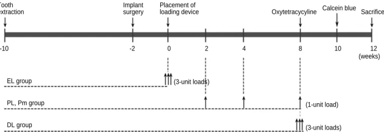
The experiment was designed with 4 groups by the loading methods, shown in Table 1. With split mouth design in dogs, a total of 12 hemi-mandibles with 24 implants were allotted to the 4 groups using a random table. All the experimental groups were loaded by different time and method (Fig. 1). One unit load was defined as the amount of load applied to the implant when the expansion screw was rotated ¾ turn, which was 0.3 mm displacement of the loading device. Early loading (EL) group was applied 3-unit loads simultaneously at the time of the load-ing device placement. Periodic loadload-ing (PL) and periodic loading with rotation mobile implantation (Pm) group were applied three cycles of 1-unit load ; at 2 weeks, 4 weeks and 8 weeks after the loading device placement. Rotation mobile implant was placed according to the Ivanoff's study17; the
implants were unstable to torque when using a wrench, but remained stable to lateral and axial loading. In this study, it was standardized that after the implant placement following the rou-tine protocol, the implant was rotated two turns clockwise with the wrench, and then positioned back again until the fixture was placed in the crestal bone level. Finally, in delayed loading (DL) group, 3-unit loads were applied simultaneously at 8 weeks after
Table 1. The experimental design
Groups Number of implant
Delayed loading (DL) 6
Early loading (EL) 6
Progressive loading, rigid implantation (PL) 6 Progressive loading, rotation mobile 6
implantation (Pm)
Total 24
Fig. 1. Loading protocols. EL: early loading, PL: periodic loading, Pm: periodic loading, rotation mobile, DL: delayed loading.
EL group PL, Pm group DL group (3-unit loads) (1-unit load) (3-unit loads) -10 -2 0 2 4 8 10 12 (weeks) Tooth extraction Implant surgery Placement of
the loading device placement. All the loading devices were removed at 12 weeks.
The Yonsei University Review Committee approved the experimental protocol for Animal Care and Use. Six young adult male Beagle dogs (15 - 25 kg) were used. The dogs were in good oral and general health and had intact maxillary and mandibu-lar dentitions. The dogs were fed a soft diet throughout the exper-imental period in order to reduce chances of mechanical interferences with healing process during food intake.
All surgical procedures were performed under general anes-thesia using atropine (0.05 mg/kg) subcutenously, xylazine (2 mg/kg) and ketamine hydrochloride (10 mg/kg) intravenously. The dogs were placed on a heating pad, intubated, administered 2% enflurane, and monitored with an electrocardiogram. After disinfecting the surgical sites, 2% lidocaine HCl with epi-nephrine 1:100,000 was administered by infiltration at the sur-gical sites. During minor experimental procedures, such as pro-phylaxis, load application through the loading device, the dogs were sedated with an intramuscular injection of 2% xylazine hydrochloride (20 mg/kg).
The dogs fasted 12 hours before the surgery to prevent vomiting. Enrofloxacin (5 mg/kg) was injected subcuta-neously, and Ketorolac tromethamine (0.5 mg/kg) was inject-ed intravenously. Under general anesthesia and infiltrative local anesthesia, second, third, and fourth premolars of both sides of the mandible were extracted. A full-thickness flap was raised in the region of four mandibular premolars; the teeth were sec-tioned bucco-lingually and extracted with forceps. The flaps were repositioned and sutured with 4-0 absorbable sutures. After surgery, amoxicillin/clavulanate (13.75 mg/kg) and clease (1 T/day) was fed for 5 days.
After three months of healing, sedation and anesthesia pro-tocol used earlier was repeated for the implant surgery. After a horizontal, crestal incision was made from the distal region
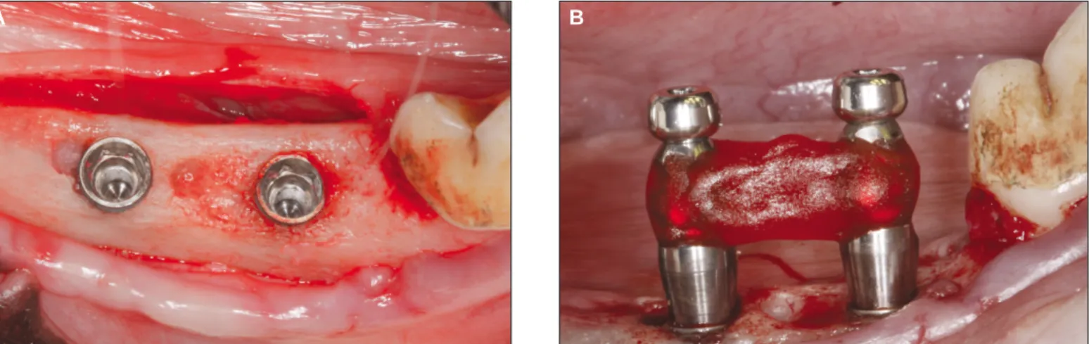
of the first premolar to the mesial region of the first molar, two 3.4 × 8.0 mm implants (FX 3408, Implantium, Dentium, Seoul, Korea), with sandblasted and acid-etched surfaces, were placed with accordance to the manufacturer's instructions, on each side of the mandible of each animal, for a total of 24 implants. The implants were placed 10 mm apart on the cre-stal bone level (Fig. 2A). The implants were placed rigidly according to the manufacturer's protocol with a torque controller except the rotation mobile implants. After implant place-ment, pick-up impression was taken on the fixture level with impression copings (DPU 4015HL, Dentium, Seoul, Korea) and self-cured acrylic resin (Pattern resin, GC, Tokyo, Japan) (Fig. 2B). Resin was added incrementally with brush-on technique to prevent polymerization shrinkage that may cause an inaccurate master model.
After the impression taking procedure, healing abutments (HAB 402035L, Dentium, Seoul, Korea) were connected into the implants; the flaps were repositioned, and then sutured. Post-operative medication was performed with same protocol as sur-gical procedures. After the loading device connection, clini-cal observations were performed weekly to ensure the loading devices were in good action, and prophylaxis was performed under the sedative procedure mentioned earlier.
Master model was made with impression copings connect-ed to the fixture analogues (DAN 34, Dentium, Seoul, Korea) and the loading device was constructed on the master model as described. Two weeks after implant placement, 2-piece type dual abutments (DAB 4515HL, Dentium, Seoul, Korea) were connected into the fixture with 25 Ncm torque. The loading devices were attached to the abutments using self cured resin modified glass-ionomer cement (Rely-X, 3M ESPE, St. Paul, MN), and then abutment screw hole was filled with cotton pel-let and temporary filling material (Caviton, GC Dental Corp., Tokyo, Japan).
Fig. 2. Implant placement and impression taking. A: The implants were placed 10 mm apart, remaining 2 mm of buccal and lingual cortex, B: Impression was taken with impression copings and pattern resin.
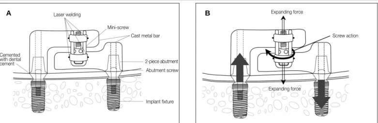
Specially designed loading device is consisted of dual abut-ments, metal bars cemented with abutabut-ments, and orthodontic expansion screw attached with metal bars (Fig. 3A). It was designed to apply controlled force, simulating static occlusal force to the implants (Fig. 3B). Upper and lower metal bars was cast with lost wax technique by Ni-Cr alloy (T3, Ticonium Co., CMP Industries Inc., Albany, NY). Prefabricated wax mold was used to standardize the size and shape of the metal bars. Expansion screws (Sectional screw mini, 600-502-30, Dentarum, Scanorto, Denmark) were attached to the center of the upper and the lower arm using alpha laser welding machine (Siro Lasertec, Pforzheim, Germany)(Fig. 3A). Total of 12 loading devices were separately cast and fabricated from their own master cast. This loading device was connected with implant fixture with abutment screw. Actual forces sim-ulating occlusal load were applied to the implant and the implant surrounding the bones by rotating the expansion screw (Fig. 3B).
After the experiment, loading devices were transferred to the master casts to verify the effectiveness of the loading device, and remaining strain was measured with three strain gauges (Kyowa, Chofu, Japan), amplifier (Kyowa, Chofu, Japan), and the data acquisition program (Kyowa, Chofu, Japan) (Fig. 4). One strain gauge was placed on the center of two implants and the other two implants were placed on the distal surface of both implants, within 1mm distance, and parallel to the line connecting the center of two implants. Strain gauges were bonded to the stone surface of master cast with a thin film of cyanoacrylate adhesive (Zapit, Dental Ventures of America, Corona, CA). Each strain gauge was separately wired, and the three strain gauges were connected to a multichannel bridge amplifier to form one leg of the bridge. All strain gauges were set to zero, and then the load was applied. After 1-unit load, the microstrain curve increased to peak strain, and then it decreased to show
flat curve over time. Second and third 1-unit loads were applied 1 minute after previous loading. The remained strain value at the time of the flat curve was recorded in units of micros-train (με). Increased remained smicros-train was recorded when each 1-unit load was applied. Descriptive statistics of remained strain after each 1-unit load was evaluated with these data. For statistic analysis, nonparametric independent t-test was used with 5% significant level and Friedman's test was also used for verification. All calculations were performed using a specif-ic statistspecif-ical program (SPSS ver. 18.0, IBM, Somers, NY). RESULTS
Table 2 shows the results of each implant, grouping, initial stability and the remarkable events during the experiment. All the experimental animals maintained good general health. Fig. 3. Diagram of the loading device. A: A schematic illustration of the loading device, B: The direction of force applied to the implant and the surrounding alveolar bone.
Laser welding
Mini-screw
Cast metal bar
2-piece abutment Abutment screw Implant fixture Cemented with dental cement A B Expanding force Screw action Expanding force
Fig. 4. Measurement of efficiency of the loading device with strain gauge. Three strain gauges were attached on the distal side of both implants and on the center of both implants.
After teeth extraction, healing occurred without complications in all the animals. During the implant placement, post-extrac-tion sites showed to be healed clinically. Implant placement was also performed without complications. However, during the loading period, some of the implants showed signs of inflam-mation around the implants. Curettage was performed to those implants under short-term general anesthesia.
Four implants, placed in dog number 2, 4, and 5, showed loss of osseointegration during the placement of the loading device, before the start of 1stloading. There were no failed
implants in EL group. DL and PL group each showed one implant failure while Pm group had two failures. During peri-odic prophylaxis and observation periods, welding failure was discovered between the metal bars and the expansion screws. The loading device was removed immediately, covering the implant with healing abutment, and the expansion screw was welded again. One loading device had a cement failure, so it was immediately cemented again. No other complications were observed.
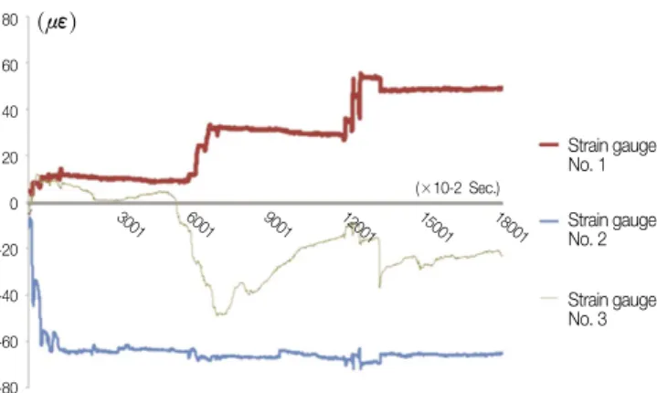
Only the data of strain gauges attached near the implant showed changes during loading device activation. Figure 5 shows the representative stress-strain curve while loading device was
acti-vated. Strain curve shows the increased value in strain gauge number 1 after three times of 1-unit loading. Positive value of strain complies with the increase in the length of area that the strain gauge was attached by the load, thus this means the area around the implant received tensile stress. In contrast, curve of strain gauge number 3 showed positive value right after the first 1-unit load, and then it showed negative value after
Table 2. Grouping, initial stability, remarkable events and the timing of event of each implants Implant Dog Left/Right Mesial/Distal
Group§ Initial Remarks Time
Number Number Position* Position* stability¶
1 1 L M PmGood
2 1 L D PmGood
3 1 R M DL Good
4 1 R D DL Good
5 2 L M EL Good Cement Failure 2 wk
6 2 L D EL Good
7 2 R M PL Poor
8 2 R D PL Poor Loss of osseointegration 7 wk
9 3 L M DL Good
10 3 L D DL Good Screw welding failure 3 wk
11 3 R M PL Good
12 3 R D PL Good
13 4 L M PmPoor Loss of osseointegration 3 wk
14 4 L D PmGood
15 4 R M DL Poor Loss of osseointegration 2 wk
16 4 R D DL Poor
17 5 L M PmPoor
18 5 L D PmPoor Loss of osseointegration 2 wk
19 5 R M EL Good
20 5 R D EL Good
21 6 L M EL Good Screw welding failure 4 wk
22 6 L D EL Good
23 6 R M PL Good
24 6 R D PL Good
*L: Left, R: Right, M: Mesial, D: Distal.
§EL: Early loaded, PL: Progressively loaded, Pm: Progressively loaded, rotation mobile, DL: delayed loaded
¶Initial stability is recorded as good when the implant stability quotient (ISQ) value exceeds 60 while ISQ value beyond 60 is recorded as poor.
Fig. 5. Representative illustration of stress-strain curve over time.
80 60 40 20 0 -20 -40 -60 -80 (με) (×10-2 Sec.) Strain gauge No. 1 Strain gauge No. 2 Strain gauge No. 3 3001 6001 9001 12001 15001 18001
second and third 1-unit load. This means the area around the implant received compressive stress. Strain gauge number 2, which was attached between the two implants showed decreased strain value after the first 1-unit load. This, how-ever, does not showremarkable changes in strain value when the loading was applied. As shown in Figure 4, strain gauge number 2 was placed relatively distant from the two implants in order to reduce the effect from the loading. descriptive sta-tistics was evaluated with the data acquired by strain gauge num-ber 1 and numnum-ber 3, excluding the data acquired by strain gauge number 2.
Table 3 shows descriptive statistics of remained strain, which was obtained by taking the absolute value of the difference of the strain values between each 1-unit load. Mean remained strain of each 1-unit load when the total three 1-unit loads were applied separately through the loading devices. Out of 24 total
strain gauges attached near the implants, data acquired by 5 strain gauges, showing irregular strain curve pattern were exclud-ed. With data obtained by 19 strain gauges, remained strains showed similar mean difference after the 1st, 2nd, and 3rd1-unit
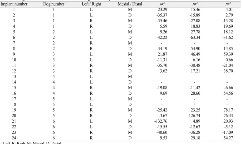
load were applied. However, the data showed high deviations. With the statistic test, the absolute values of remained strain were not different after three 1-unit loadings (P=.532). Changed strain value of each implant is shown in Table 4. Some of the data showed that the amount of remained strain after three 1-unit loading was similar, however, others showed different changes of strain value under disparate series of loading. DISCUSSION
This study was performed prior to the future study about the relationship between the loading applied to the implant and the
Table 3. Mean absolute value of remained strain after loading
Absolute value of remained strain (με)
1stloading 2ndloading 3rdloading
Mean (n = 19) 27.06a 31.40b 28.28c
SD 28.696 27.86 24.811
* a = b = c (P=.532, Chi-square = 1.263, df = 2, by Friedman's test with 95% significant level)
Table 4. Changed strain value after each 1-unit loading on each implant
Implant number Dog number Left / Right Mesial / Distal με1 με2 με3
1 1 L M 23.29 15.46 4.01 2 1 L D -35.37 -15.89 2.79 3 1 R M -35.46 -27.08 -13.28 4 1 R D 5.59 18.83 19.69 5 2 L M 9.26 27.78 18.12 6 2 L D -42.22 -63.34 -31.62 7 2 R M - - -8 2 R D 34.19 54.90 14.85 9 3 L M 21.87 46.49 59.39 10 3 L D -11.31 6.16 0.66 11 3 R M -35.70 -30.48 -21.04 12 3 R D 3.62 17.21 38.70 13 4 L M - - -14 4 L D - - -15 4 R M -19.08 -11.42 -6.66 16 4 R D 9.69 28.60 54.56 17 5 L M - - -18 5 L D - - -19 5 R M -25.42 23.25 78.17 20 5 R D -3.67 126.74 76.43 21 6 L M -132.76 4.89 20.93 22 6 L D -15.55 -12.63 -5.12 23 6 R M -40.60 -36.28 -17.09 24 6 R D 9.53 29.18 54.27
L: Left, R: Righ, M: Mesial, D: Distal.
με1: Changed strain after 1stloading; με2: Changed strain after 2ndloading; με3: Changed strain after 3rdloading, + tension, - compression.
alveolar bone regeneration. It has been widely accepted that mechanical loading plays an important role in development, maintenance, and adaptation of the skeleton.18As a result of
cyclic mechanical load, sustained micro-fractures may occur around the implants. Newly formed bone can replace micro-fractured bony areas and avoid fatigue fracture of the bone under bone remodeling process. And this bone adaptation process is dependent on strain magnitude, duration, frequency, history, type and distribution.19
In this study, the loading device was designed to verify that early, progressive and delayed loading might affect bone remodeling in dogs. Previous studies were performed in ani-mals to apply occlusal load directly to the implants through the fixed prostheses. However, the chewing patterns of these animals are different from those of humans, so the loads transferred to the implants were unpredictable. Also, it is dif-ficult to regulate the amount of force directly applied to the implant because the occlusal force is different among individual animals used in those studies. Gotfredsen et al. designed the static loading devices with orthodontic expansion screws attached between the two metal crowns supported by implants.20
This design could not simulate the true occlusal loading, because the direction of applied load was perpendicular to the long axis of the implant. So, in this study, the loading device was designed to apply loads more parallel to the long axis of implant in order to simulate the clinical conditions.
The height of the loading device was standardized 10 mm for upper metal bar, and 8 mm for the lower metal bar, and the length of the loading device was determined to be 10 mm apart between the center of implants. This dimension allows load-ing device to not interfere with upper teeth but to provide suf-ficient space for the attachment of the expansion screw and sufficient rigidity of the metal bar. The loading device was designed with cement type prosthesis. It has been broadly used in regular practices because of the convenience and the eco-nomic benefits. In this study, cemented type loading device was used to simulate the clinical conditions. During the loading peri-od, prophylaxis and clinical observations were performed to ver-ify cement failure. There was no cement failure except one load-ing device, whichoccurred in the EL group. It was cemented immediately and the loading was applied normally.
One unit load was defined as the transferred load when the expansion screw rotated 3/4 turns clockwise. When the expan-sion screw rotates 1/4 turn, the linear amount of displacement was 0.1 mm. If the one unit load is applied, total amount of dis-placement would be 0.3 mm. Supposing that the load was trans-ferred equally to both implants, each implant would undergo 150 ㎛ of movement. It has been suggested that micro-movement of 28 ㎛ or less have no adverse effect on osseoin-tegration, whereas micro-movement of 150 ㎛ or more may lead to fibrous tissue healing.21,22 Therefore, one unit load
was designed to apply maximum load to the implant, not
exceeding 150 ㎛ displacement. However, in the experi-ment, the load could not be equally transferred to each implant. One implant endured 150 ㎛ of micro-movement and the other was able to bear over 150 ㎛. This is one of the rea-sons implant failure rate was particularly higher in this study than in other studies.
The loading devices were remounted on the master casts, and remaining strains were measured with strain gauges. During the activation of loading devices, remaining strain was record-ed. These data revealed the aspect of loading through the load-ing devices. The loadload-ing devices were designed to apply axial direction of loads to the implants. But with these stress-strain analyses, it showed the directions of loads applied to the implants were different in the loading devices. In other words, it was predicted that the loading device would apply tensile force to one implant while compressive force to the other implant. In reality, compressive force and tensile force were com-bined to each implant after loading. Only one strain gauge was attached to the distal side of the implant so that the remained strain curves do not show proportional values after three load-ings. This is one of the reasons that the data was highly deviated. If more strain gauges had been used around the implant, more accurate result would have appeared in this study.
Each 1-unit loading was applied one minute after previous loading. This was to eliminate the damping effect, which means that the strain value went up to the highest point and then decreased over time. In the pilot study on the stone model, there was no difference among the waiting time of 10, 5, and 1 minute, thus one-minute gap between each loading was performed in this study. Stress-strain analysis was performed on the master cast level. It was the most accurate method that the stress strain analysis can be performed on the alveolar bone of the study animals because force applied to alveolar bone was directly cal-culated using strain and elastic modulus of the alveolar bone. However, it is extremely difficult to attach strain gauges directly to the alveolar bone of the study animal, so it was per-formed on the master cast. Instead of calculating the force applied to the alveolar bone, the amount of remained strain was compared when the loading was applied to the implants. Pilot study was performed using polyurethane foam (Saw Bone, pacific Research Laboratories Inc., Vashon, WA) with acrylic resin (Ortho-Jet, Lang dental, Wheeling, IL) to verify the difference in the result between the alveolar bone and the stone cast. The result showed no difference of stress strain on the stone model compared to that of polyurethane foam.
To verify the effectiveness of the loading devices, absolute value of the remained strain after the loading was used. As both the tensile and the compressive force acted on the surface to which the strain gauge was attached, the amount of real compressive or tensile force was compared by taking the average of the absolute values of the remained strain. Though standard deviation was relatively high by each loading device,
it showed no difference in the average absolute value of remained strain after each 1-unit load. It can be assumed from these stress-strain analyses that the loading devices transferred similar amount of loads to the implant effective-ly while not appeffective-lying loads parallel to the long axis of the implant. In this study, 4 implants failed; two in Pm group, one in PL and DL group. In this experiment, healing abutments were direct-ly inserted after implant placement. Subsequent placement of the loading device may be affected by forces generated by tongue and other oral tissues in the implants with low initial stabili-ty. The other reason of high implant failure rate may be due to the differences in general health condition among the dogs. Few dogs were not in a good general health condition from the start-ing point of the experiment compared with other dogs. Durstart-ing teeth extraction, there were no difficulty in those dogs. In addi-tion, during implant placement, the quality of the alveolar bone was very poor with thin cortical bone and loose trabecular bone. There are some limitations of this loading device. Loading forces applied to the implants were static load, which is different from the dynamic load that takes place in natural oral cavity.23,24Jemt
et al. reported that static load generated by prosthesis misfit had not changed the marginal bone level.25This means static load
might not affect remodeling around the implant. To improve this problem, Duyck et al. designed a device to apply static and dynamic load.26However, with this study on rabbit tibiae, no
significantly lower bone to implant contact was found around the dynamically loaded implants in comparison to that of the statically loaded implants. Future study with adjusted loading device to apply static dynamic load is required.
CONCLUSION
Specialized design of implant loading device for animal study model was introduced. Similar amount of loads was applied near the implant after each 1-unit loading, while the direction of the loads was not parallel to the long axis of the implants as predicted before study.
REFERENCES
1. Testori T, Wiseman L, Woolfe S, Porter SS. A prospective mul-ticenter clinical study of the Osseotite implant: four-year interim report. Int J Oral Maxillofac Implants 2001;16:193-200. 2. Cochran DL, Morton D, Weber HP. Consensus statements
and recommended clinical procedures regarding loading protocols for endosseous dental implants. Int J Oral Maxillofac Implants 2004;19:109-13.
3. Ledermann P. Bar-prosthetic management of the edentulous mandible by means of plasma-coated implantation with titani-um screws. Dtsch Zahnarztl Z 1979;34:907-11.
4. Romanos G, Froum S, Hery C, Cho SC, Tarnow D. Survival rate of immediately vs delayed loaded implants: analysis of the current literature. J Oral Implantol 2010;36:315-24.
5. Rocci A, Martignoni M, Burgos PM, Gottlow J, Sennerby L. Histology of retrieved immediately and early loaded oxidized implants: light microscopic observations after 5 to 9 months of
loading in the posterior mandible. Clin Implant Dent Relat Res 2003;5:88-98.
6. Romanos GE, Nentwig GH. Immediate versus delayed functional loading of implants in the posterior mandible: a 2-year prospec-tive clinical study of 12 consecuprospec-tive cases. Int J Periodontics Restorative Dent 2006;26:459-69.
7. Hoshaw SJ, Brunski JB, Cochran GVB. Mechanical loading of Branemark implants affects interfacial bone modeling and re-modeling. Int J Oral Maxillofac Implants 1994;9:345-60. 8. Frost HM. Wolff's Law and bone's structural adaptations to
me-chanical usage: an overview for clinicians. Angle Orthod 1994;64:175-88.
9. Binon PP, Sullivan DY. Provisional fixed restorations technique for osseointegrated implants. J Calif Dent Assoc 1990;18:23-30. 10. Misch CE. Contemporary Implant Dentistry. 2nd ed. St Louis:
Mosby, 1999, p. 595-608.
11. Appleton RS, Nummikoski PV, Pigno MA, Cronin RJ, Chung KH. A radiographic assessment of progressive loading on bone around single osseointegrated implants in the posterior maxil-la. Clin Oral Implants Res 2005;16:161-7.
12. Roberts WE. Bone tissue interface. J Dent Educ 1988;52:804-9. 13. Jayme SJ, de Oliveira RR, Muglia VA, Novaes AB Jr, Ribeiro RF. The effects of different loading times on the bone re-sponse around dental implants: a histomorphometric study in dogs. Int J Oral Maxillofac Implants 2010;25:473-81.
14. Gostovic′AS, Todorovic′A, Lazic′V, Todorovic′A, Milinkovic′
I, Lekovic′V. Immediate implant loading with fixed dental restora-tions-an animal model study. Vojnosanit Pregl 2012;69:181-9. 15. Rismanchian M, Attar BM, Razavi SM, Shamsabad AN, Rezaei
M. Dental implants immediate loading versus the standard 2-staged protocol: an experimental study in dogs. J Oral Implantol 2012;38:3-10.
16. Rismanchian M, Bajoghli F, Gholamreza T, Razavi M. Clinical, histological and histomorphometrical evaluation of early loaded implants (an animal study). J Oral Implantol 2012 Jan 3. 17. Ivanoff CJ, Sennerby L, Lekholm U. Influence of initial implant
mobility on the integration of titanium implants. An experimental study in rabbits. Clin Oral Implants Res 1996;7:120-7. 18. Tanck E, Homminga J, van Lenthe GH, Huiskes R. Increase in
bone volume fraction precedes architectural adaptation in growing bone. Bone 2001;28:650-4.
19. Turner CH. Three rules for bone adaptation to mechanical stimuli. Bone 1998;23:399-407.
20. Gotfredsen K, Berglundh T, Lindhe J. Bone reactions adjacent to titanium implants subjected to static load. A study in the dog (I). Clin Oral Implants Res 2001;12:1-8.
21. Brunski JB. Biomechanical factors affecting the bone-dental im-plant interface. Clin Mater 1992;10:153-201.
22. Szmukler-Moncler S, Piattelli A, Favero GA, Dubruille JH. Considerations preliminary to the application of early and im-mediate loading protocols in dental implantology. Clin Oral Implants Res 2000;11:12-25.
23. Mishra M, Ozawa S, Masuda T, Yoshioka F, Tanaka Y. Finite element study on the effect of abutment length and material on implant bone interface against dynamic loading. J Adv Prosthodont 2011;3:140-4.
24. Sohn BS, Heo SJ, Koak JY, Kim SK, Lee SY. Strain of implants depending on occlusion types in mandibular implant-support-ed fiximplant-support-ed prostheses. J Adv Prosthodont 2011;3:1-9.
25. Jemt T, Book K. Prosthesis misfit and marginal bone loss in eden-tulous implant patients. Int J Oral Maxillofac Implants 1996;11:620-5.
26. Duyck J, R�nold HJ, Van Oosterwyck H, Naert I, Vander Sloten J, Ellingsen JE. The influence of static and dynamic load-ing on marginal bone reactions around osseointegrated im-plants: an animal experimental study. Clin Oral Implants Res 2001;12:207-18.