2
강릉원주대학교 치과대학 보철학교실 및 구강과학연구소
허윤혁1,2․이양진1․김대곤2․조리라2․박찬진2
NovelGuide
™임플란트 시스템은 골량과 골질을 수술 전에 판단하여 점막을 젖히지 않고 미리 계획된 스텐트와 보철물을 이용하여 즉시하중을 부여하는 CAD/CAM 기반의 임플란트 보철 치료방법이다. 환자의 불편감을 최소 화하여 미리 예측 가능한 위치에 임플란트를 식립함으로써 술 후 합병증 및 보철과정을 간소화 할 수 있는 장점이 있다.
본 증례의 환자는 56세 남성으로 상,하악 부분 무치악 상태였으며, 상악전치부 보철물 탈락과 하악 전치가 흔들 린다는 주소로 내원하였다. 이에 상악 잔존치 모두와 하악 4전치 발거 및 치주치료를 실시한 뒤 임시 의치를 6개 월간 사용하여 발치와 치유 및 의치 적응여부를 평가하였다. 골량은 충분하다고 판단되었고 환자의 협조도와 경 제적인 여건, 전신건강 등 여러 사항이 양호하여 CAD/CAM 기반의 수술템플렛을 이용한 무판막 수술을 통해, 미
리 제작된 임시 고정성 보철물로 즉시하중을 부여하는 상악 NovelGuide
™임플란트 시스템을 계획하였다. 사용
중인 임시의치를 이용하여 제작한 방사선 스텐트로 CT를 촬영하고, computer based planning (Procera
Ⓡsoftware)을 통해 3차원적인 골형상과 각 부위별 단면상을 참고하여 상악에 8개의 임플란트 식립체를 생역학적 관점 및 골조 건을 고려하여 분산 배치하였다. 미리 제작된 임시 고정성 보철물을 임플란트 수술 후 즉시 장착 및 하중을 부여 하여 기능하도록 하였으며 6개월 후 골유착 정도를 평가한 뒤 금속구조물을 이용한 최종 보철물을 제작하였다.
하악의 경우 전치부 도재전장주조금속관과 우측 구치부 임플란트 보철물 제작을 통해 상, 하악 치료를 마무리하 였다.
주요어: CAD/CAM, 즉시하중, 수술템플렛, 무판막 수술, 임시고정성보철물
(
구강회복응용과학지 2012:28(4):423~439)
교신저자:
박찬진
강릉원주대학교 치과대학 치과보철학교실,
강원도 강릉시 강릉대학로 1번지, 201-702, 대한민국.
Fax: + 82-33-640-3103, E-mail: [email protected]
원고접수일: 2012년 09월 03일, 원고수정일: 2012년 11월 02일, 원고채택일: 2012년 12월 25일
서 론
치과치료에 있어 임플란트를 이용한 보철수복 방법은 유용하고 획기적인 치료법이지만 장점과 단점, 적응증과 비적응증이 점점 더 명확해지고 있는 실정이다.
1이러한 임플란트 치료를 성공적 으로 진행하기 위해서는 수술 및 보철 등의 모든 과정이 적절해야 하지만, 무엇보다도 최종보철 과정까지 고려한 잘 계획된 수술이 필수적이다.
더구나, 무치악 환자의 임플란트를 이용한 보철 치료의 경우는 인접치가 없고 수직고경 상실, 안 모변화 등으로 무치악 이라는 특유의 난제 직면하고 있기에 보다 더 정확한 수술 및 보철계 획이 요구된다.
2,3컴퓨터 단층촬영(computed tomography, CT) 및 컴퓨터 설계 및 제작(CAD/CAM) 기술은 수술 전 프로그램상에서 해부학적 구조물과 골량의 삼차 원적 정보를 이용한 구체적인 치료계획을 가능 하게 하였으며, 인터넷을 통한 데이터 전송을 통 해 정학한 수술템플렛(surgical template)을 제작 할 수 있게 되었다.
4-7이와 더불어 50-150㎛ 정도의 미세동요가 골유 착을 방해하지 않는다는 사실에 근거하여 대두 된 즉시하중 및 조기하중 치료 방법과 더불어 수 술템플렛을 점막상에서 고정함으로써 수술당일 피판형성 과정없이 식립 후 임시보철물까지 치 료가 가능하게 되었다.
8-16빠르고 정확한 수술, 무판막에 따른 술 후 합병증의 감소, 당일 보철 이라는 여러 장점들로 인해 계획된 식립 위치, 각도 등과 실제 값과의 오차, 광범위한 골이식을 동반한 경우 적응이 어렵다는 단점에도 불구하 고 점차 그 활용도가 확대되고 있다.
17-21이번 증례보고에서는 상악 무치악 상태에서 CAD/CAM 기술을 이용하여 임플란트 식립을 계 획하고 수술템플렛을 이용하여 판막의 거상 없 이 식립한 다음 임시보철물을 연결함으로써 수 술 당일 즉시하중을 가한 증례를 보고하고자 한 다.
증 례
1. 과거병력 및 구강검사
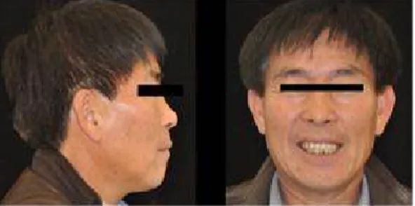
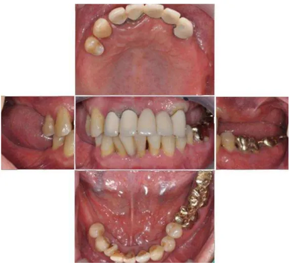
양악 부분무치악 상태의 56세의 남환이 앞니 잇몸이 붓고 흔들려서 보철상담을 받고 싶다는 주소로 내원하였다. 구강 외를 관찰한 결과 낮은 미소선을 제외하고는 수직고경 상실 등의 특이 사항은 없었으나(Fig. 1), 구강 내 임상 검사 결과 모든 상악 잔존치에서 교합성 외상을 동반한 만 성치주염으로 인해 예후가 지극히 불량한 상태 였으며, 하악 잔존치의 경우 전반적으로 중등도 의 치조골 흡수를 동반한 만성치주염 소견을 보 였고 특히 하악 전치부의 예후가 매우 불량한 상 태였다(Fig. 2). 파노라마 및 치근단 방사선사진 에서도 전반적인 치조골 소실 및 상악우측중절 치와 상악좌측견치의 치근단 병소가 관찰되었다 (Fig. 3,4).
2. 치료계획
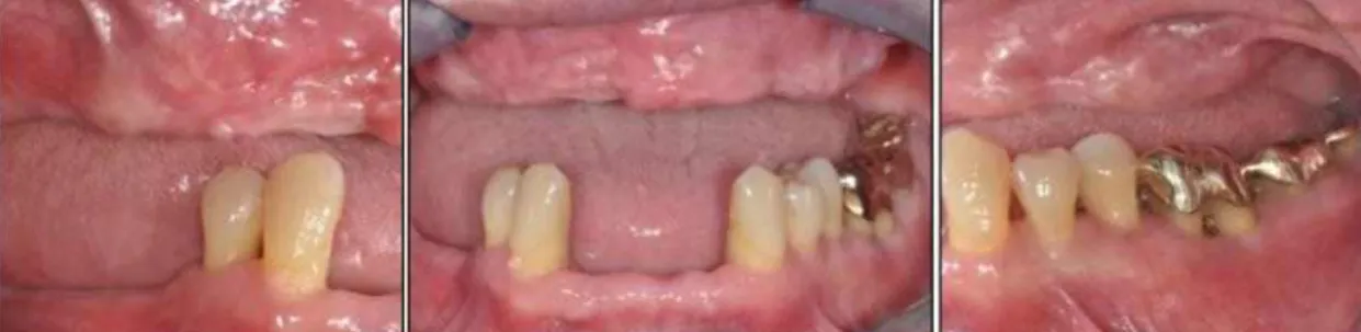
보철 전 처치로 예후가 지극히 불량한 상악 모 든 잔존치와 하악 전치 발거 및 잔존치 적극적인 치주치료를 시행한 뒤 임시 가철성 보철물을 통 해 발치와의 치유 및 최종 치료계획을 준비하였 다(Fig. 5~7).
상악의 경우 무치악 상태였기에 최종보철물은 전통적인 방식의 총의치부터 임플란트 지지고정
Fig. 1. External examination: low smile line.
Fig. 2. Intraoral examination: chronic periodontitis, TFO sign due to insufficient posterior teeth stop
Fig. 3. Panoramic view: moderate alveolar bone loss
Fig. 4. Periapical view: apical lesion on
maxillary right central tooth and left
canine, severe alveolar bone loss on
mandibular anterior teeth.
Fig. 5. panoramic view: extraction of hopless teeth
성 보철까지 다양한 선택을 할 수 있었으나, 골 흡수량이 크지 않으며(Fig. 3), 제 I급 악간관계 및 악간거리가 10mm이내 이고, 낮은 미소선과 협순지지가 충분하여 고정성 보철물이 가능하다 고 판단되었다. 하지만 비교적 얇고 가동적인 점 막을 가지고 있어 점막을 광범위하게절개하는 전통적인 임플란트 식립 수술의 경우점막의 과 도한 변형 및 퇴축이 우려되었다(Table I). 또한
Fig. 7. Frontal and lateral view after extraction and active perio treatment
Bone loss
Occlusal relation
Occlusal
space Lip support Mucosa type Smile line Fixed Minimal Class I Less than
10mm Sufficient Thick,
keratinized Low Removable Severe Class II More than
15mm Insufficient Thin, movable high Table I. Check points of clinical examinations
Fig. 6. Temporary partial denture
환자의 협조도와 경제적인 여건, 전신건강 등 여
러 사항이 양호하였기에 CAD/ CAM 기반의 수
술템플렛을 이용한 무판막 수술을 통해, 미리 제
작된 임시 고정성 보철물로 즉시하중을 부여하
는 상악 NovelGuide
™임플란트 시스템을 계획하
였다. 하악의 경우 전치부는 좌,우 견치를 지대
치로 하는 고정성 보철물과 우측 구치부의 임플
란트 식립을 계획하였다.
Fig. 8. Computed tomography (CT) view: moderate alveolar bone resorption.
Fig. 9. Class I occlusal relation and occlusal space less than 10mm.
3. 치료과정
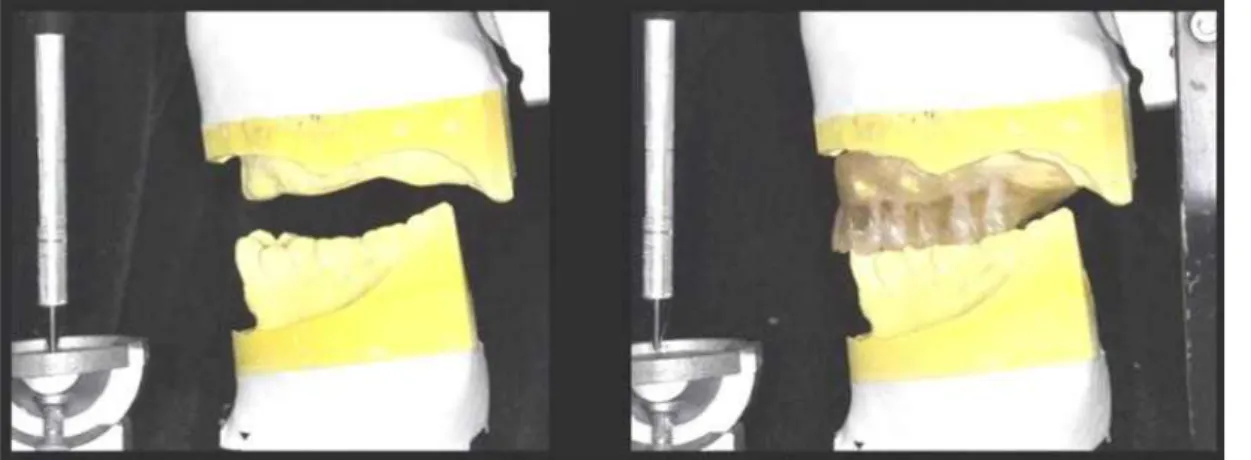
상악 잔존치 발치 후 사용 중이던 임시의치를 이용한 이중스캔기법(double-scan technique)을 활 용하여 영상을 얻었다. 이중스캔법이란 먼저 악 간기록과 함께 레진상 의치를 장착한 채로 스캔 한 다음(Fig 10), 방사선 스텐트만 따로 스캔함으
로써(Fig. 11) 이중으로 이미지 데이터를 얻는 방
법인데, 이 때 얻어진 DICOM 데이터는
CAD/CAM 소프트웨어(Procera software; Nobel-
Biocare)에 맞는 파일로 변환된다. 이중스캔법으
로 얻은 데어터는 소프트웨어에서 중첩시킨 후
소프트웨어에서 영상을 회전하고 삼차원적으로
분석함으로써 환자가 가진 고유한 골량과 골질
Fig. 10. Temporary dentures and interocclusal record
Fig. 11. Radiographic guide scan without index
에 대한 정보를 얻을 수 있다. 이를 바탕으로 상 악에 8개의 적절한 직경과 길이의 임플란트 식립 체(Nobel Replace Tapered Groovy;Nobel Biocare) 를 선택하여 생역학적 관점 및 골조건을 고려하 여 분산 배치하였다(Fig 12). 또한 이미지 데이터 는 Procera 가공센터로 보내져 수슬용템플릿을 제작하는데 이용되었다.(Fig. 13). Computer based planning (Procera
Ⓡsoftware)을 통해 미리 제작된 임시 고정성 보철물이 임플란트 수술 후 즉시 장 착 및 하중 부여가 기능하도록 준비하였다(Fig.
14).
수술템플렛을 계획한 위치에 정확히 고정하기 위하여 미리 준비한 악간관계기록을 이용하고수 평고정핀을 이용하여 상악에 고정하였다(Fig.
15,16).
수평고정핀은 수술을 위한 드릴을 시행하는
Fig. 12. Three dimensional image-based treat- ment planning software (Procera
Ⓡsoftware; NobelBiocare)
Fig. 13. Stereolithographic surgical template
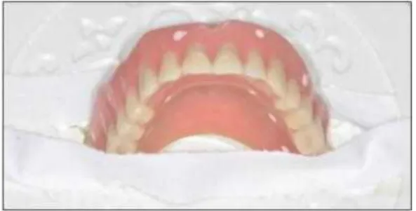
Fig. 14. Prefabricated provisional fixed prosthesis
동안 수술용템플렛의 움직임을 최소화하기 위한 목적으로 사용되는 장치이다. 국소마취를 시행 하고 8개의 임플란트를 무피판술식으로. 미리 계 획하였던 위치와 각도, 깊이를 가지도록 주의하 면서 식립하였다(Fig 17,18).
모든 임플란트는 45N/cm 의 식립 토오크를 가
지도록 식립하였다. 수술템플렛을 제거한 후 미
리 계획했던 종류의 지대주(muti-unit abutments;
Fig. 15. The surgical template was positioned with the centric relation interocclusal record
Fig. 16. Three stabilizing transverse pins fix surgical template
Fig. 17. Fixture placement
Fig. 18. Implant installation using surgical template
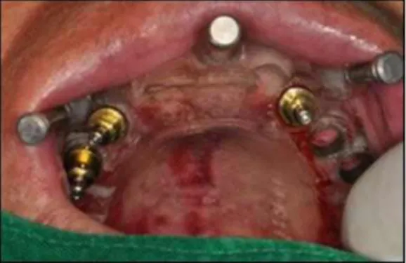
Fig. 19. A. Removal of transverse pins and surgical template, B. Abutments connection
Nobel Biocare)를 임플란트 고정체에 연결하고 제조사에서 권장하는 토오크로 체결하였다(Fig.
19). 미리 제작된 임시보철물을 구강 내에 시적 및 자가중합 아크릴레진(Jet, Lang dental, Wheeling, USA)을 이용한 이장 과정을 거쳤다 (Fig. 20). 중십교합에서는 양측으로 균일하게 접 촉하도록 하고, 편심위 운동 시 가능한 교합력이 분산되도록 교합조정하였다. 임시보철물을 구강 외로 제거하여 연마한 후 장착하고 티타늄나사 는 손으로 체결하였다. 보철물을 장착한 후 임플 란트 고정체와 지대주 및 임시실린더의 적합도 를 치근단방사선사진을 통해 확인한 후 환자에 게 사용 시 주의사항을 설명하였다. 환자는 수술 후 큰 불편감 호소없이 빠르게 임시보철물에 잘 적응하였다(Fig. 21).
6개월 간 환자의 적응도를 관찰하였는데 환자
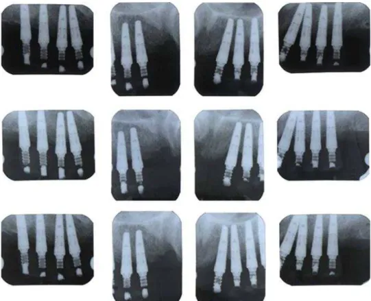
는 저작 및 심미에 만족하였으며 식립 1, 3, 6개 월 경과 시 촬영한 치근단 방사선사진에서도 어 떠한 골유착실패의 징후나 뚜렷한 변연골흡수 소견을 보이지 않았다(Fig. 22).
임시보철물을 제거한 후 이전용(transfer) 인상 코핑을 지대주에 체결하여 실리콘인상재(Express
Fig. 20. Provisional fixed prosthesis: direct relined with acrylic resin
Fig. 21. Intraoral views of temporary prostheses try-in.
VPS Impression, 3M ESPE, St. Paul, MN)를 이용 하여 최종 임플란트 보철물 제작을 위한에 인상 을 채득하였다(Fig. 23). 지대주의 위치와 연조직 을 재현한 주모형을 초경석고(Fujirock EP, GC corporation, Tokyo, Japen)를 이용하여 제작하였 다(Fig. 24).
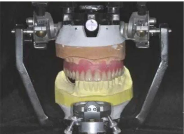
상악의 교합제를 제작한 후 임시보철물의 교 합고경과 악간기록을 참고하여 악간관계를 채득 하였으며 안궁이전을 시행하였다(Fig. 25~28).
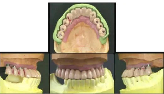
교합기에서 치아배열을 시행한 후 구강 내 납 의치를 시적하여 최종적인 형태 및 안모등을 평 가하였다(Fig. 29). 환자는 구순부 돌출 안모의 개 선을 원하였으며, 이에 가용한 수평 피개(overjet) 범위 내에서 상악 전치부 순측경사 감소하여 치 아배열 및 보철물 제작 시 이를 반영하고자 하였 다(Fig. 30,31).
납형 형성 및 되깍기 과정을 거쳐 제작된 금속
코핑을 구내 장착하여 적합도를 확인한 뒤 악간
관계를 채득하였다. 최종보철물을 완성하였다
(Fig. 32~35).
Fig. 22. Periapical views at 1st, 3rd, and 6th month from immediate loading.
Fig. 23. Final impression with transfer type
impression coping and polyvinyl siloxane. Fig. 24. Fabrication of master cast
Fig. 25. Occlusal rim
Fig. 26. Jaw relation
Fig. 27. Facebow transfer for definitive prosthesis
Fig. 28. Wax denture for final appearance assessment
Fig. 29. Wax denture try-in
최종보철물 기능 6개월까지 관찰한 결과 유의 한 수준의 골변화 관찰되지 않으며, 양호한 위생 관리상태와 더불어 도재파절등의 제반 문제 발 생없이 잘 사용하고 있다.(Fig. 36~38)
고 찰
무판막 식립과 더불어 수술 당일 임시고정성 보철물을 장착함으로써 일상생활이 바로 가능하 고환자로 하여금 심미적으로나, 심리적으로 만 족감을 준다는 점은 큰 장점이다.
4,17,18,20또한 임 시보철물 상에서 수직고경 및 안모의 변화 등을 관찰 및 수정, 적응여부가 가능함으로써 성공적 인 최종보철물 제작이 용이하다. 하지만 CAD/
CAM을 이용한 임플란트 즉시하중 치료법은 환
자의 불편감을 최소화하고 수술시간을 단축할
Fig. 30. Full contour wax-up
Fig. 31. Cut-back: check for porcelain space using PVS index.
Fig. 32. Fabrication metal copings
Fig. 33. Metal copings try-in: passive adaptation confirm
Fig. 34. Fabrication of definitive prostheses
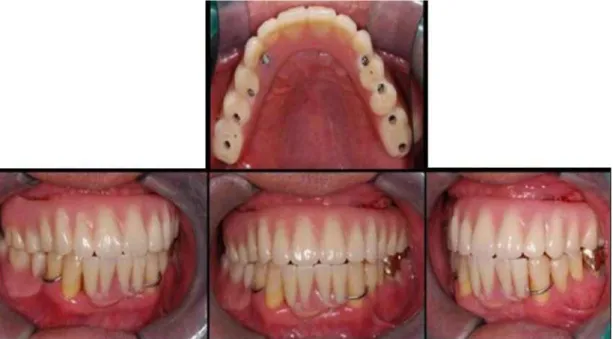
Fig. 35. Intraoral view of definitive implant supported PFM bridge.
Fig. 36. Panoramic view of definitive prostheses
Fig. 37. Periapical views of definitive prostheses after six monthes.
Fig. 38. Change of the appearance before and after the treatment.
수 있지만 여러 가지 합병증을 유발할 수도 있
다.
19,21,22Yong과 Moy는
22즉시하중의 조기 합병
증으로 임플란트가 실패할 수도 있으며, 골수준 이 방사선사진과 차이가 나서 보철물의 안착을 방해할 수도 있다고 하였다. 또한 기능 후 보철 물 나사가 풀리거나, 발음문제, 양측성 볼씹기 등의 보철후 합병증을 보일 수 있지만, 보철물에 적응해 감에 따라 해결되는 문제라고 하였다.
본 증례에서도 임시보철물 장착 후 처음 한달 간은 환자는 좌측 볼이 씹힌다는 증상이 존재하 였으나 점차 사라졌으며, 임시보철물 장착 6개월 기간 동안 정기적인 방사선 검사 및 교합 확인을 통해 임플란트 식립 후 즉시하중에 따른 뚜렷한 변연골 흡수 없이 유지됨을 확인 할 수 있었다.
오히려 상악 임플란트 임시 보철물에 의한 교합 력 증가가 당시 최후방지대치였던 하악 우측 제 1소구치의 외상성교합을 유발하여 근관치료 및 도재주조관 수복 치료를 실시하였다.
이러한 CAD/CAM을 이용한 임플란트 수술법
은 정밀한 계획이 가능하지만 계획된 위치와 실
제 식립위치간의 오차는 존재한다.
23,24식립위치
인 중의 하나로 점막상에 위치하는 수술용템플 릿을 지목하였다. Dreiseidier 등25, Eggers 등26의 실험연구에서도 어떠한 CAD/CAM 시스템을 이 용하더라도 계획된 임플란트와 실제 식립된 임 플란트의 식립 위치, 각도, 깊이의 오차가 필연 적으로 발생하게 되며 실제 임상에서도 더 불리 한 상황일 수 있다고 언급하고 있다.
본 증례에서도 수술 당일 미리 제작된 임시보 철물의 조직면 아크리레진을 이용한 이장을 통 해 실제 구강 내 연조직과의 적합도를 수정하는 과정이 필요하였다.
수술 시 수술용템플렛의 확실한 고정도 중요 한 요소인데, 이를 위해 고정핀을 대신하여 임시 임플란트와 같은 형태의 고정나사를 이용한다면 보다 나은 정밀성을 기대할 수 있을 것이다.
결 론
본 증례에서 CAD/CAM 기술을 이용하여 고정 성 임플란트 임시보철물이 수술 전 미리 제작이 가능하였다. 이중스캔법을 통해 얻어진 CT 정보 를 통해 술자는 임플란트 식립 전용 프로그램을 통해 인공치의 위치와 치조골의 해부학적 구조 물을 미리 분석할 수 있었다. 수술 과정에 있어 수술용템플렛을 구강 내 정확한 위치에 고정시 키는 것은 계획된 위치에 적은 오차로 임플란트 식립에 필수적이다. 수술 당일 즉시 장착 및 기 능을 부여한 임시보철물은 6개월 간 심미성과 기능성을 평가한 후 이에 근거하여 최종보철물 이 제작되었으며, 현재 최종보첢물 기능 18개월
2. Park H, Hwang J. Implant overdenture & fixed complete prosthesis. . Well Pub. Co. Seoul 3. Sadowsky SJ. The implant-supported prosthesis for
the edentulous arch: design considerations. J Prosthet Dent 1997; 78: 28-33.
4. Tee-Khin N, Cheng AC, Lee H, Wee AG, Leong EW. The management of a completely edentulous patient using simultaneous maxillary and mandibular CAD/CAM-guided immediately loaded definitive implant-supported prostheses: a clinical report. J Prosthet Dent 2008; 99: 416-420.
5. Fuster-Torres MA, Albalat-Estela S, Alcaniz-Raya M, Penarrocha-Diago M. CAD / CAM dental systems in implant dentistry: update. Med Oral Patol Oral Cir Bucal 2009; 14: E141-145.
6. Strub JR, Rekow ED, Witkowski S. Computer-aided design and fabrication of dental restorations: current systems and future possibilities. J Am Dent Assoc 2006; 137: 1289-1296.
7. Verstreken K, Van Cleynenbreugel J, Marchal G, Naert I, Suetens P, van Steenberghe D.
Computer-assisted planning of oral implant surgery: a three-dimensional approach. Int J Oral Maxillofac Implants 1996; 11: 806-810.
8. Szmukler-Moncler S, Piattelli A, Favero GA, Dubruille JH. Considerations preliminary to the application of early and immediate loading protocols in dental implantology. Clin Oral Implants Res 2000;
11: 12-25.
9. Gapski R, Wang HL, Mascarenhas P, Lang NP.
Critical review of immediate implant loading. Clin Oral Implants Res 2003; 14: 515-527.
10. Ostman PO. Immediate/early loading of dental
implants. Clinical documentation and presentation of
a treatment concept. Periodontol 2000 2008; 47:
90-112.
11. Degidi M, Piattelli A, Felice P, Carinci F. Immediate functional loading of edentulous maxilla: a 5-year retrospective study of 388 titanium implants. J Periodontol 2005; 76: 1016-1024.
12. Horiuchi K, Uchida H, Yamamoto K, Sugimura M.
Immediate loading of Branemark system implants following placement in edentulous patients: a clinical report. Int J Oral Maxillofac Implants 2000; 15:
824-830.
13. Bergkvist G, Sahlholm S, Karlsson U, Nilner K, Lindh C. Immediately loaded implants supporting fixed prostheses in the edentulous maxilla: a preliminary clinical and radiologic report. Int J Oral Maxillofac Implants 2005; 20: 399-405.
14. Aalam AA, Nowzari H, Krivitsky A. Functional restoration of implants on the day of surgical placement in the fully edentulous mandible: a case series. Clin Implant Dent Relat Res 2005; 7: 10-16.
15. Wolfinger GJ, Balshi TJ, Rangert B. Immediate functional loading of Branemark system implants in edentulous mandibles: clinical report of the results of developmental and simplified protocols. Int J Oral Maxillofac Implants 2003; 18: 250-257.
16. Ioannidou E, Doufexi A. Does loading time affect implant survival? A meta-analysis of 1,266 implants.
J Periodontol 2005; 76: 1252-1258.
17. Balshi SF, Wolfinger GJ, Balshi TJ. Surgical planning and prosthesis construction using computed tomography, CAD/CAM technology, and the Internet for immediate loading of dental implants. J Esthet Restor Dent 2006; 18: 312-323; discussion 324-315.
18. Kupeyan HK, Shaffner M, Armstrong J. Definitive CAD/CAM-guided prosthesis for immediate loading of bone-grafted maxilla: a case report. Clin Implant Dent Relat Res 2006; 8: 161-167.
19. van Steenberghe D, Glauser R, Blomback U, Andersson M, Schutyser F, Pettersson A, Wendelhag I. A computed tomographic scan-derived customized surgical template and fixed prosthesis for flapless surgery and immediate loading of implants in fully edentulous maxillae: a prospective multicenter study.
Clin Implant Dent Relat Res 2005; 7 Suppl 1:
S111-120.
20. Marchack CB. An immediately loaded CAD/CAM- guided definitive prosthesis: a clinical report. J Prosthet Dent 2005; 93: 8-12.
21. Van Assche N, van Steenberghe D, Guerrero ME, Hirsch E, Schutyser F, Quirynen M, Jacobs R.
Accuracy of implant placement based on pre-surgical planning of three-dimensional cone-beam images: a pilot study. J Clin Periodontol 2007; 34: 816-821.
22. Yong LT, Moy PK. Complications of computer-aided- design/computer-aided-machining-guided (Nobel- Guide) surgical implant placement: an evaluation of early clinical results. Clin Implant Dent Relat Res 2008; 10: 123-127.
23. Eggers G, Patellis E, Muhling J. Accuracy of template-based dental implant placement. Int J Oral Maxillofac Implants 2009; 24: 447-454.
24. Valente F, Schiroli G, Sbrenna A. Accuracy of computer-aided oral implant surgery: a clinical and radiographic study. Int J Oral Maxillofac Implants 2009; 24: 234-242.
25. Dreiseidler T, Neugebauer J, Ritter L, Lingohr T, Rothamel D, Mischkowski RA, Zoller JE. Accuracy of a newly developed integrated system for dental implant planning. Clin Oral Implants Res 2009; 20:
1191-1199.
26. Eggers G, Senoo H, Kane G, Muhling J. The accuracy of image guided surgery based on cone beam computer tomography image data. Oral Surg Oral Med Oral Pathol Oral Radiol Endod 2009; 107:
e41-48.
Department of Prosthodontics, Section of dentistry, Seoul National University Bundang Hospital, Seongnam, Korea Department of Prosthodontics and Research Institute of Oral Science, College of Dentistry, Gangneung-Wonju National
University, Gangneung, Korea
This case report described a technique utilizing a computer-aided design (CAD) / computer-aided machining (CAM) - guided surgical implant placement and prefabricated temporary fixed prosthesis for an immediately loaded restoration. The advantages of CAD/CAM guided implant procedures are flapless, minimally invasive surgery and shorter surgery time. With this technique, less postoperative morbidity and delivery of prosthesis for immediate function would be possible. A patient with an edentulous maxilla received 8 implants in maxilla using CAD/CAM surgical templates. Prefabricated provisional maxillary implant supported fixed prosthesis were connected immediately after implant installation. Provisional prosthesis was evaluated for aesthetics, function during 6 months. Definitive implant supported fixed porcelain fused metal bridges were fabricated.
Key words: CAD/CAM, immediate loading, flapless surgery, prefabricated prosthesis
Correspondence to : Prof. Chan-Jin Park
Department of Prosthodontics, College of Dentistry, Gangneung-Wonju National University, 1, GangneungDaehangno, Gangneung, Gangwon-Do, 210-702, Korea.
Fax: + 82-33-640-3103, E-mail: [email protected]
Received: September 03, 2012, Last Revision: November 02, 2012, Accepted: December 25, 2012