Introduction
Dental implant has become a reliable and predictable rehabilitation method for edentulous area in oral cavity.1-3However, long-term research has reported mechanical complications, including screw loosening, fracture, and implant fractures.4Frequent complica- tions of the external connection is the loosening of the abutment screw.5 To minimize the joint instability between implant and abutment, inter- nal tapered connection types have been introduced, and become wide- ly spread.6,7
Several studies have reported superior joint stability of internal tapered connection than external butt-joint connection.8-10Internal
tapered connection showed better resistance to the bending force11 and lower incidence of mechanical complications in comparison with the external butt-joint connection type.12
However, there is increasing concern about the axial displacement of abutment into the implant with internal tapered connection.
For implants with internal tapered connection, certain amount of axi- al displacement occurs during abutment tightening.13,14Accordingly, many researches have focused on the axial displacement of implant- abutment assembly. Repeated tightening, at least twice, have been recommended to minimize the settling effect during the connection of abutment into implant.15In a recent study of cyclic loading, the axial displacements were observed both in external and internal implant
Effect of cyclic loading on axial displacement of abutment into implant with internal tapered connection: a pilot study
Hyon-Woo Seol1, DDS, MSD, Seong-Joo Heo1*, DDS, MS, PhD, Jai-Young Koak1, DDS, MSD, PhD, Seong-Kyun Kim1, DDS, MSD, PhD, Chong-Hyun Han2, DDS, MSD, PhD
1Department of Prosthodontics, School of Dentistry, Seoul National University, Seoul, Korea
2Department of Prosthodontics, Gangnam Severance Dental Hospital, College of Dentistry, Yonsei University, Seoul, Korea
Purpose: To evaluate the axial displacement of implant-abutment assembly after cyclic loading in internal tapered connection system. Materials and methods: External butt-joint connection implant and internal tapered connection implant were connected with three types of abutment for cement-retained prostheses, i.e. external type abutment (Ext group), internal tapered 1-piece abutment (Int-1 group), and internal tapered 2-piece abutment (Int-2 group). For each group, 7 implants and abutments were used. The implant- abutments assemblies were clamped into the implant holder for vertical loads. A dynamic cyclic loading was applied for 150 ± 10 N at a frequency of 4 Hz. The amount of axial displacement of the abutment into the implant was calculated at each cycle of 0, 5, 10, 50, 100, 1,000, 5,000, and 10,000. A repeated measures analysis of variance (ANOVA) for the overall effect of cyclic loading and the pattern analysis by linear mixed model were used for statistical analysis. Differences at P<.05 were considered statistically significant. Results: The mean axial displacement after 10,000 cycles were 0.714 ± 0.488 ㎛ in Ext group, 5.286 ± 1.604 ㎛ in Int-1 group, and 11.429 ± 1.902
㎛ in Int-2 group. In the pattern analysis, Int-1 and Int-2 group showed continuous axial displacement at 10,000 cycles. There was no declining pattern of axial displacement in the Ext group. Conclusion: The pattern of linear mixed model in Ext group showed no axial displacement. There were continuous axial displacements in abutment-implant assemblies in the Int-1 and Int-2 group at 10,000 cycles. More axial displacement was found in Int-2 group than in Int-1 group. (J Korean Acad Prosthodont 2013;51:315-22)
Key words: Dental implant-abutment design; Internal tapered connection; Cyclic loading; Axial displacement; Settling effect
c cc
2013 The Korean Academy of Prosthodontics
This is an Open Access article distributed under the terms of the Creative Commons Attribution Non-Commercial License (http://creativecommons.org/licens- es/by-nc/3.0) which permits unrestricted non-commercial use, distribution, and reproduction in any medium, provided the original work is properly cited.
*Corresponding Author: Seong-Joo Heo
Department of Prosthodontics, School of Dentistry, Seoul National University, 275-1 Yeongeon-Dong, Jongno-Gu, Seoul, 110-768, Korea
+82 2 2072 2661: e-mail, [email protected]
Article history: Received October 2, 2013 / Last Revision October 10, 2013 / Accepted October 14, 2013
*The implants and abutments were provided by Warantec Implant Co., Seoul, Korea.
after 1,000,000 cycles.16However, the study simulated the labora- tory procedure with implant replica, not with implant itself.
The discrepancy of axial displacement was observed between implant-abutment and replica-abutment group, i.e., the implant and the implant replica showed different amount of axial dis- placement.14Therefore, the implant-abutment assembly would be more appropriate for simulating the oral condition, rather than implant replica-abutment assembly.
The aim of this study, therefore, was to evaluate the axial dis- placement of implant-abutment assembly, not replica-abutment, after cyclic loading in internal tapered connection system.
Materials and methods 1. Cyclic loading machine
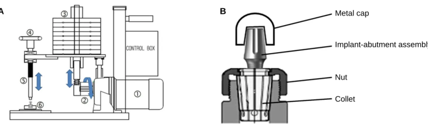
The custom-made cyclic loading machine (Hatis Co., Hwaseong, Korea) was manufactured to simulate human chewing movement by using a cam and motor (Fig. 1A). As the pear-shaped cam rotates, the cam-housing cylinder makes contact with the abutment and applies chewing-like cyclic loads to it.17
The specimens were clamped into implant holder composed of collet and nut (Nikken, Japan) (Fig. 1B) by using torque wrench (230DB3, Tohnichi, Japan) in 30 kgf∙cm and this assembly was con-
nected to the stainless steel holder. The assembly was fixed to the holder along the long axis of implant for vertical loads. The verti- cal loads would have a definitive effect on the axial displacement of the abutment to the implant. A hemispherical metal cap made of stainless steel was manufactured and seated onto the unmodified abut- ments (Fig. 1B).
2. Implants and abutments
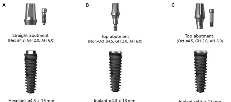
Two different implant systems produced by Warantec (Seoul, Korea) were prepared. In this study, external type implant (Hexplant� ø 4.3 × 13 mm, Art.No. FHT43130, Seoul, Korea) and internal type implant (Inplant�ø 4.3 × 13 mm, Art.No. FIT43130, Seoul, Korea) were used (Table 1 and Fig. 2). Hexplant�has an external hex at the prospective connection with abutment, and Inplant�has an internal octagonal connection between the implant and abutment. The implant-abutment interfaces were external butt joint and 7 degree tapered internal connection, respectively.
Three types of abutment for cement-retained prostheses were used in this study. Straight Abutment�(ø 4.3, gingival height 2.0 mm, abut- ment height 6.0 mm Art.No. H0SA4326H, Seoul, Korea) was used for external type implant (Ext group), (Fig. 2A). Top Abutment� of 1-piece type (non-octagonal, ø 4.5, gingival height 2.0 mm, abut- ment height 6.0 mm Art.No. I0TA4526, Seoul, Korea) and Top
Fig. 1. Custom-made cyclic loading apparatus. A: Cyclic loading machine, ①: motor, ②: cam, ③: weight, ④: height adjusting screw ⑤: impact rod, ⑥: implant holder, B: Implant-abutment assembly was clamped into implant holder (collet and nut).
A B Metal cap
Implant-abutment assembly
Nut Collet
Table 1. Implant and abutment systems used in this study (7 samples per group)
Group Implant system/diameter Art No. Abutment Art No.
Ext Hexplant�, 4.3 mm FHT43130 Straight Abutment�(ø 4.3, GH 2.0, AH 6.0) H0SA4326H
Int-1 Inplant�, 4.3 mm FIT43130 Top Abutment�(Non-Oct ø 4.5, GH 2.0, AH 6.0) I0TA4526
Int-2 Inplant�, 4.3 mm FIT43130 Top Abutment�(Oct ø 4.5, GH 2.0, AH 6.0) I0TA4526E
Abutment�of 2-piece type (octagonal, ø 4.5, gingival height 2.0 mm, abutment height 6.0 mm Art.No. I0TA4526E, Seoul, Korea) were used for internal type implant, respectively (Int-1 and Int-2 group), (Fig. 2B and Fig. 2C).
For each group, seven implants and abutments were used, and each
assembly was clamped in an implant holder (Fig. 1B).
Each implant and abutment was connected and the torque was applied twice at 20 Ncm at a 10 minute interval using a digital torque gauge (MGT50, Mark-10 Co., Hicksville, NY, USA) (Fig. 3). In the instructions for user of the manufacturer, tightening at 30 Ncm was recommended. However, in this study, the desired torque was set to 20 Ncm to magnify the difference between groups.
The external type implant group was regarded as a control group that showed a less axial displacement than internal tapered implant group.16
3. Setting the applied load
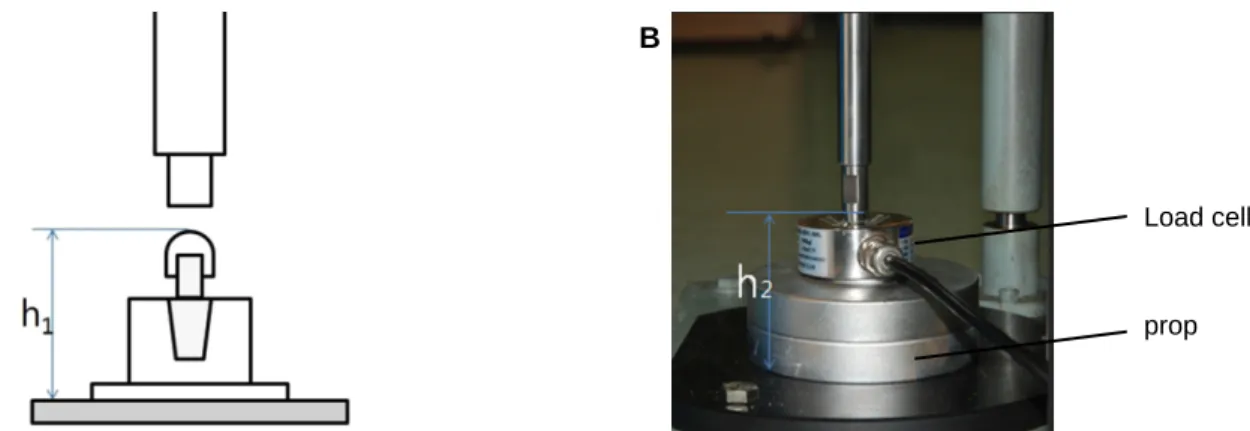
According to whole height (h1) from the metal hemispherical cap to the base of implant holder, the prop for load cell was fabricated for same height (h2), i.e., h1= h2(Fig. 4).
Each applied load was measured with a load cell (MNC-500L, CAS Korea, Seoul, Korea) and strain analysis program (STT-200P, CAS Korea, Seoul, Korea). A force of 150 N, which is within the physiologic clinical range,18,19was set to be applied. The applied loads were adjusted to 150 ± 10 N by adjusting the height of impact posi- tion. In all experiments, loads of 150 ± 10 N at a frequency of 4 Hz were applied. The dynamic cyclic loads were confirmed by mon- itoring the strain analysis program (Fig. 5).
Fig. 2. This picture shows three groups of implant-abutment assemblies. A: Ext group (left): Straight abutment�was connected to Hexplant�implant, B: Int-1 group (center): 1-piece type Top abutment�(non-octagonal) was connected to Inplant�implant, C: Int-2 group (right): 2-piece type Top abutment�(octagonal) was connected to Inplant�implant.
A B C
Fig. 3. Digital torque gauge (MGT50) was used to tighten the abutment into implant at desired torque.
4. Measuring the length of implant-abutment assembly
The total length of implant-abutment assemblies were mea- sured using an electronic digital micrometer (No. 293-240, Mitutoyo, Kawasaki, Japan), which was held in a vise. The initial length of implant-abutment assemblies were measured after torque was applied twice at a 10 minute interval (Fig. 6). Thereafter, the total length of implant-abutment assemblies were measured at each cycle of 0, 5, 10, 50, 100, 1,000, 5,000, and 10,000. The measurements were made by the same operator and were accurate up to 0.001 mm (1 ㎛) and the amount of axial displacement of the abutment into the
implant was calculated by comparing the total length measurements of implant-abutment assemblies at each cycle.
5. Statistical analysis
Statistical analysis was performed using a repeated measures analy- sis of variance (ANOVA) for the overall effect of cyclic loading to the axial displacement of implant-abutment assemblies, and the inde- pendent samples T-test for post hoc comparison were conducted using SPSS 20 (IBM SPSS, USA). Differences at P<.05 were considered statistically significant.
In addition, the patterns of axial displacement according to the cyclic loading in each group were analyzed using R version 3.0.1 (The R foundation for Statistical Computing, Vienna, Austria) with pack- age lme4: Linear mixed-effects models.20The mean responses at each cycle were transformed to common logarithmic scale to fit linear mixed models. Thereafter, the formula for this model was determined.
Fig. 4. Setting the applied load with a load cell. A: Height from metal cap to base of implant holder (h1) was measured for each implant-abutment assembly, B: The prop was adjusted for the load cell to be the same height (h1= h2).
A B
Load cell
prop
Fig. 6. Electronic digital micrometer.
Fig. 5. Monitoring the applied load using strain analysis program (STT-200P).
160.0000 150.0000 140.0000 130.0000 120.0000 110.0000 100.0000 90.0000 80.0000 70.0000 60.0000 50.0000 40.0000 30.0000 20.0000 10.0000 0.0000 -10.0000
00:00:40 00:00:41 00:00:42 00:00:43
N
Time
Results
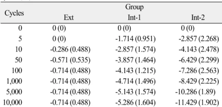
The mean axial displacements of the abutment into the implant are shown in Table 2. There was significantly more axial dis- placement in the Int-1 and Int-2 group than that of Ext group.
The mean axial displacement after 10,000 cycles were 0.714 ± 0.488
㎛ in Ext group, 5.286 ± 1.604 ㎛ in Int-1 group, and 11.429 ± 1.902 ㎛ in Int-2 group. Int-2 group showed the highest amount of axial displacement after cyclic loading followed in order by Int-1 and Ext group.
Mauchly's test indicated that the assumption of sphericity had been violated (x2= 96.78, P<.0001), therefore multivariate tests were used.
The results revealed that the changes of axial displacement value showed statistically significant difference between groups (P<.05).
An independent samples T-test was performed for each group at
corrected significance level by Bonferroni's method for post hoc com- parison. A significant difference was found at each cycle between Ext and Int-1 group. Also, significant difference was found between Ext and Int-2 group at each cycle except cycle 5. However, for inter- nal tapered implant-abutment group (Int-1 vs. Int-2), significant dif- ference was found only after 1,000 cycles. Statistically significant difference was not found between Int-1 and Int-2 until 100 cycles.
The patterns of axial displacement for each group were analyzed by linear mixed models in R Statistics with package lme4. The pat- terns in logarithmic scale of each group revealed a breakpoint at 1.35, which is original value of at 21.387 cycles (Fig. 7 A and B). The Ext group showed no declining pattern in both before and after the break- point (P>.05). However, in the Int-1 and Int-2 group, there were con- tinuous declining patterns with different slope in both before and after the breakpoint (Table 3).
Table 2. Mean (SD) axial displacement of implant-abutment samples at each cycles (㎛)
Cycles Group
Ext Int-1 Int-2
0 0 (0) 0 (0) 0 (0)
5 0 (0) -1.714 (0.951) -2.857 (2.268)
10 -0.286 (0.488) -2.857 (1.574) -4.143 (2.478) 50 -0.571 (0.535) -3.857 (1.464) -6.429 (2.299) 100 -0.714 (0.488) -4.143 (1.215) -7.286 (2.563) 1,000 -0.714 (0.488) -4.714 (1.496) -8.429 (2.225) 5,000 -0.714 (0.488) -5.143 (1.574) -10.286 (1.89) 10,000 -0.714 (0.488) -5.286 (1.604) -11.429 (1.902) Ext: External type implant; Int-1: Internal type implant with 1-piece abutment; Int- 2: Internal type implant with 2-piece abutment.
Table 3. The patterns of axial displacement with a breakpoint at 1.35 in logarithmic scale
Slope Estimate SE t value P-value
β11 -0.4456 0.5214 -0.855 .4027
β12 -0.1085 0.2498 -0.434 .6689
β21 -2.7607 0.5214 -5.295 <.0001
β22 -0.6516 0.2498 -2.608 .0168
β31 -4.1734 0.5214 -8.005 <.0001
β32 -2.0970 0.2498 -8.394 <.0001
SE: standard error
In βab, ''β'' denotes a regression coefficient, subscript ''a'' refer to the group (1: Ext group, 2: Int-1 group, 3: Int-2 group), and subscript ''b'' refer to the cycle (1: cycle
≤ 1.35, 2: cycle > 1.35 in logarithmic scale).
Fig 7. The patterns of axial displacement of each group with linear mixed models. A: fitted models of axial displacement in logarithmic scale, B: fitted models of axial displacement in original values.
A B
Discussion
The results of this study indicate a certain amount of axial dis- placement of abutment into implant according to the applied cyclic loading, especially in the internal tapered connection type design.
Ext group was set as a control group to compare with Int groups.
In the Ext group, the amount of axial displacement of 0.714 ㎛ was achieved at 100 cycles, and no more axial displacement was found until 10,000 cycles. In the pattern analysis, no axial displacement was found in Ext group. However, internal tapered implant showed more axial displacement than external type implant. Furthermore, Int-2 group showed more axial displacement than Int-1 group.
Between Int-1 and Int-2 groups, the values of axial displacement became statistically different after 1,000 cycles.
The result of this study is comparable with the results of earlier study which reported that internal implant group showed more axi- al displacement than that of the external implant group.16The external type implant with a flat platform interface showed least amount of axial displacement (2.5 ㎛ for external implant group), and more axial displacement was found at internal tapered implant (8.1 ㎛ for internal implant group) after 1,000,000 cycles of 250 N loading for abutment-replica system with 30 Ncm tightening.
In the study of axial displacement of abutment as a function of tight- ening torque for implants and implant replicas, the different values for implant and implant replica group were found.14In this regard, previous studies recommended that the abutment screws should be retightened twice at 30 Ncm at a 10 minute interval in all laboratory and clinical procedures, as the axial displacement of abutment with a function of applied tightening torque occurs.15,21,22However, these studies are confined to the effect of tightening torque before cyclic loading application.
In this study, the tightening torque of 20 Ncm was applied, although the manufacturer recommended 30 Ncm tightening. The amount of axial displacement in 20 Ncm tightening was less than in 30 Ncm tightening.14In this regard, the authors postulated that the change of amount of axial displacement would be magnified and can be easily detected after cyclic loading. However, recommended tight- ening torque of 30 Ncm is necessary in the further study.
The authors adopted the collet and nut system in measuring the axial displacement of abutment into the implant after repeated tightening torque. This system enabled the authors to mount and dis- assemble the abutment-implant assemblies from the implant hold- er with convenience. In virtue of simplicity of assembling, the length of implant-abutment assemblies were measured easily whenever it is necessary.
As the length of implant-abutment assemblies were measured at exponential pattern of cyclic loadings, the cycles were transformed
to logarithmic scale for convenience. The patterns of axial displacement were analyzed by linear mixed models, and the formula was deter- mined. As the breakpoint of pattern was found at 1.35 in logarith- mic scale, the original value of cycles at 21.387 was determined. That is, significant axial displacement had occurred until 21 cycles.
However, in Int-1 and Int-2 group, continuous axial displacement in implant-abutment assemblies were found after 21 cycles and until 10,000 cycles without any plateau. In this study, the cyclic loading was applied up to 10,000 cycles. The 10,000 cycles correspond to only about 3.6 to 4.6 days in clinical situation.19,23Since the expla- nation by Bozkaya and Muftu that axial location of tapered inter- ference fit would converge on the certain extent,13the axial displacement of abutment of Int-1 and Int-2 group could be speculated to converge at a specific value. However, in this study, the specific value or extent was not found during 10,000 cycles. Therefore, additional cyclic load- ing is required to calculate the specific extent.
Axial displacement was not noticed after 100 cycles in the Ext group with a total amount of less than 1 ㎛. In this regard, the axial dis- placement of external butt-joint implant can be neglected in clini- cal situations. Therefore, in the clinical case of vertical stability is essential, the external butt-joint implant would be more appropriate.
Since this study was conducted with a specific company, the results may not provide generalized conclusion for other companies' implant systems. Therefore, additional experiments and clinical stud- ies are imperative to acquire more generalized data.
Conclusion
Within the limitations of this study, following conclusions can be drawn:
1. The pattern of linear mixed model in Ext group showed no axi- al displacement.
2. There were continuous axial displacement in abutment-implant assemblies during 10,000 cycles in the Int-1 and Int-2 group.
3. More axial displacement was found in Int-2 group than Int-1 group after 10,000 cycles.
References
1. Jemt T. Fixed implant-supported prostheses in the edentulous max- illa. A five-year follow-up report. Clin Oral Implants Res 1994;
5:142-7.
2. Buser D, Mericske-Stern R, Bernard JP, Behneke A, Behneke N, Hirt HP, Belser UC, Lang NP. Long-term evaluation of non-sub- merged ITI implants. Part 1: 8-year life table analysis of a prospective multi-center study with 2359 implants. Clin Oral Implants Res 1997;8:161-72.
3. Nelson K, Semper W, Hildebrand D, Ozyuvaci H. A retro- spective analysis of sandblasted, acid-etched implants with re-
duced healing times with an observation period of up to 5 years. Int J Oral Max Impl 2008;23:726-32.
4. Goodacre CJ, Bernal G, Rungcharassaeng K, Kan JY. Clinical complications with implants and implant prostheses. J Prosthet Dent 2003;90:121-32.
5. Jemt T, Pettersson P. A 3-year follow-up study on single implant treatment. J Dent 1993;21:203-8.
6. Sutter F, Weber HP, Sorensen J, Belser U. The New Restorative Concept of the ITI Dental Implant System: Design and Engineering. Int J Periodont Rest 1993;13:408-31.
7. Norton MR. Assessment of cold welding properties of the internal conical interface of two commercially available implant systems.
J Prosthet Dent 1999;81:159-66.
8. Khraisat A, Stegaroiu R, Nomura S, Miyakawa O. Fatigue resistance of two implant/abutment joint designs. J Prosthet Dent 2002;88:
604-10.
9. Merz BR, Hunenbart S, Belser UC. Mechanics of the implant- abutment connection: An 8-degree taper compared to a butt joint connection. Int J Oral Max Impl 2000;15:519-26.
10. Kitagawa T, Tanimoto Y, Odaki M, Nemoto K, Aida M.
Influence of implant/abutment joint designs on abutment screw loosening in a dental implant system. J Biomed Mater Res B Appl Biomater 2005;75B:457-63.
11. Norton MR. An in vitro evaluation of the strength of an internal conical interface compared to a butt joint interface in implant de- sign. Clin Oral Implants Res 1997;8:290-8.
12. Schwarz MS. Mechanical complications of dental implants.
Clin Oral Implants Res 2000;11:156-8.
13. Bozkaya D, Muftu S. Mechanics of the tapered interference fit in dental implants. J Biomech 2003;36:1649-58.
14. Dailey B, Jordan L, Blind O, Tavernier B. Axial Displacement of Abutments into Implants and Implant Replicas, with the Tapered Cone-Screw Internal Connection, as a Function of
Tightening Torque. Int J Oral Max Impl 2009;24:251-6.
15. Kim KS, Lim YJ, Kim MJ, Kwon HB, Yang JH, Lee JB, Yim SH. Variation in the total lengths of abutment/implant assemblies generated with a function of applied tightening torque in exter- nal and internal implant-abutment connection. Clin Oral Implants Res 2011;22:834-9.
16. Lee JH, Kim DG, Park CJ, Cho LR. Axial displacements in ex- ternal and internal implant-abutment connection. Clin Oral Implants Res 2012:1-7.
17. Kim SK, Koak JY, Heo SJ, Taylor TD, Ryoo S, Lee SY. Screw Loosening with Interchangeable Abutments in Internally Connected Implants After Cyclic Loading. Int J Oral Max Impl 2012;27:42-7.
18. Richter E-J. In Vivo Vertical Forces on Implants. Int J Oral Max Impl 1995;10:120-40.
19. Rosentritt M, Behr M, Gebhard R, Handel G. Influence of stress simulation parameters on the fracture strength of all-ceramic fixed-partial dentures. Dental materials: official publication of the Academy of Dental Materials 2006;22:176-82.
20. Bates D, Maechler M, Bolker B. lme4: Linear mixed-effects mod- els using S4 classes. R package version 0.999999-2. http://CRAN.R- project.org/package=lme4. 2013.
21. Siamos G, Winkler S, Boberick KG. Relationship between im- plant preload and screw loosening on implant-supported prostheses.
J Oral Implantol 2002;28:67-73.
22. Bakaeen LG, Winkler S, Neff PA. The effect of implant diam- eter, restoration design, and occlusal table variations on screw loos- ening of posterior single-tooth implant restorations. J Oral Implantol 2001;27:63-72.
23. Wiskott HWA, Nicholls JI, Belser UC. Stress Fatigue: Basic Principles and Prosthodontic Implications. Int J Prosthodont 1995;8:105-16.
내측연결형 임플란트에 체결한 지대주의 수직침하에 대하여 반복하중이 미치는 영향
설현우1∙허성주1*∙곽재영1∙김성균1∙한종현2
1서울대학교 치의학대학원 치과보철학교실, 2연세대학교 강남세브란스병원 치과보철과
연구 목적: 내측연결형 임플란트와 지대주의 연결체에 반복하중을 부여하였을 때 수직 침하를 평가하고자 하였다.
연구 재료 및 방법: 외측연결형 임플란트와 내측연결형 임플란트에 세 종류의 시멘트유지형 지대주를 각각 장착하였다. 즉, 외측연결형 지대주(Ext 그룹), 내측연결형 1-piece 지대주(Int-1 그룹), 내측연결형 2-piece 지대주(Int-2 그룹)를 사용하였으며, 각 그룹마다 7개의 시편을 준비하였다. 임플란트-지대주 연결체에 수직하중을 적용하기 위 하여 임플란트 받침대에 고정한 후, 4 Hz의 빈도로 150 ± 10 N의 반복하중을 가하였다. 수직침하량은 0, 5, 10, 50, 100, 1,000, 5,000, 10,000회의 반복하중 후에 각각 측정하였다.
반복측정분산분석(RM-ANOVA)를 이용하여 반복하중의 영향을 분석하였으며, 패턴변화를 관찰하기 위하여 선형혼합모형(linear mixed model)을 사용하였다. 유의수준은 5%
로 설정하였다.
결과: 10,000회 반복하중 후 수직침하량은, Ext 그룹에서 0.714 ± 0.488 ㎛, Int-1그룹에서 5.286 ± 1.604 ㎛, Int-2 그룹에서 11.429 ± 1.902 ㎛를 나타내었다. 패턴분석에서는, Int-1 그룹 및 Int-2 그룹에서 지속적인 수직침하가 관찰되었으며, Ext그룹에서는 수직침하현상이 관찰되지 않았다.
결론:10,000회 반복하중 후의 선형혼합모형을 통한 분석에서, Ext그룹은 수직침하현상을 보이지 않았으나, Int-1 및 Int-2 그룹은 지속적인 수직침하현상을 나타내었다. 또한, Int-2그룹에서 Int-1그룹보다 더 많은 수직침하량이 관찰되었다. (대한치과보철학회지 2013;51:315-22)
주요단어: 임플란트-지대주 디자인; 내측연결구조; 반복하중; 수직침하; 침하현상
*교신저자: 허성주
110-768 서울특별시 종로구 연건동 275-1 서울대학교 치의학대학원 치과보철학교실 02-2072-2661: e-mail, [email protected]
원고접수일: 2013년 10월 2일 / 원고최종수정일: 2013년 10월 10일 / 원고채택일:
2013년 10월 14일
2013 대한치과보철학회
이 글은 크리에이티브 커먼즈 코리아 저작자표시-비영리 3.0 대한민국 라이선스에 따라 이용하실 수 있습니다.
c cc