Vol. 22, No. 6 (2012)
292
†
Corresponding author
E-Mail : [email protected] (Y. K. Lee)
Design Optimization of Dental Implants Using Finite Element Analysis for Injecting Bioactive Materials
Kangsoo Lee and Yong Keun Lee*
,†Xerochem Inc., 713-1 Seo-ri, Idong-myun, Cheoin-gu, Yongin-si, Gyeonggi-do 449-834, Korea
*Graduate School of NID Fusion Technology, Seoul National University of Science and Technology, 172 Gongneung-2 Dong, Nowon-Gu, Seoul 139-743 Korea
(Received March 29, 2012 : Received in revised form May 16, 2012 : Accepted May 31, 2012)
Abstract
In order to improve osseointegration of dental implants with bone we studied an implant with holes inside its body to deliver bioactive materials based on a proposed patent. Bioactive materials can be selectively applied through holes to a patient according to diagnosis and the integration progress. After the bioactive material is applied, bone can grow into the holes to increase implant bonding and also enhance surface integration. In order to improve the concept and study the effect of bioactive material injection on implant integration, design optimization and integration research were undertaken utilizing the finite element method. A 2-dimensional simulation study showed that when bone grew into the holes after the bioactive material was injected, stress vertically distributed in the upper part of the implant was relieved and mild stress appeared at the opening of the injection holes. This confirmed the effect of the bioactive material and the contribution of the injection holes, but the maximum stress increased ten-fold at the opening. In order to reduce the maximum stress, the size, location, and the number of holes were varied and the effects were studied. When bioactive materials formed an interface layer between the implant and the mandible and four holes were filled with cortical and cancellous bones all the stress concentrated opposite to the loading side without holes disappeared. The stresses at the four outlets of the holes was mildly elevated but the maximum stress value was ten-fold greater compared to the case without the bioactive material.Key words
dental implant, finite element, bioactive materials, osseointegration, holes.1. Introduction
A dental implant is an artificial tooth root used in den- tistry to support restorations that resemble a tooth or group of teeth.
1-2)Dental implants can be used to support a number of dental prostheses, including crowns, implant- supported bridges or dentures.
3-7)The majority of dental implants currently available are shaped like small screws, with either tapered or parallel sides. They can be placed at the same time as a tooth is removed by engaging with the bone of the socket wall and sometimes also with the bone beyond the tip of the socket.
Current evidence suggests that implants placed straight into an extraction socket have comparable success rates to those placed into healed bone.
8)The success rate and radiographic results of immediate restorations of dental implants placed in fresh extraction sockets (the temporary crowns placed at the same time) have been shown to be comparable to those obtained with delayed loading (the crowns placed weeks or months later) in carefully selected cases.
9)A typical implant consists of a titanium screw (resem- bling a tooth root) with a roughened or smooth surface.
The majority of dental implants are made out of com- mercially pure titanium, which is available in 4 grades depending upon the amount of carbon and iron contained.
More recently grade 5 titanium has increased in use. Grade 5 titanium, Titanium 6AL-4V, is believed to offer similar osseointegration levels as commercially pure titanium. Ti- 6Al-4V alloy offers better tensile strength and fracture resistance. Today most implants are still made out of commercially pure titanium (grades 1 to 4) but some implant systems are fabricated out of the Ti-6Al-4V alloy.
Implant surfaces may be modified by plasma spraying, anodizing,
10)etching or sandblasting to increase the surface area and the integration potential of the implant.
An implant, be it dental, orthopedic or other, is usually
a biologically compatible material, like titanium, which is
surgically inserted within the body to replace defective
structures such as bone or teeth. Although these implants
are becoming more commonplace, problems still remain
in the area of osseointegration, both immediate and long-
term. Most implant procedures focus mainly on mech-
anical repair without much thought as to regeneration of
bone. It has been shown that the replacement of bones
such as hip joints that initially osseointegrate properly deteriorate years later because of osteolysis at the bone to implant interface.
In order to lengthen the lifetime of implants and to accelerate the bone healing process, some research focuses on improving the initial anchorage of the implant as well as on preserving the strength of the bone to implant interface. However, none of these current approaches are satisfactory.
The encapsulated biological agents are loaded into the hollow and porous implant and promote the growth of new bone or tooth structures. The combination of porosity and controlled release techniques produce a new dental and/or orthopedic implant system that accelerates bone ingrowth and osseointegration (integration of, e.g. titanium into host bone or teeth). The controlled release technology delivers scheduled doses of growth factors and/or other chemical and/or pharmacological substances in a pre- defined temporal and spatial manner to promote bone in growth and/or osseointegration. The physical signs of the pores and hollow cylinder can be altered to optimize bone ingrowth and/or osseointegration.
The aim of this study is to design an implant body with holes through which bioactive materials are effectively injected while maintaining mechanical strength of an im- plant using finite element analysis. This study consists of three phases and the effect of making injection holes on stress distribution obtained during the first phase is reported in this article.
2. Experimental Procedure
2-dimensional (2-D) simulation was used in the first phase of the study, which included the structural properties of an implant and holes, the effect of bioactive material on stress distribution, and properties of holes such as location, shape, and the number. The diameters of 0.2 to 1 mm and 0.2 to 2 mm were studied for an inlet and an outlet of a hole, respectively. Locations of an inlet, outlets, and connecting holes were varied to optimally re- distribute and reduce stress on an implant. The number of outlets was varied between 2 to 5.
The second phase of the study will improve the results obtained from the first phase with 3-dimentional (3D) structural design. In order to accomplish this goal 3D model will be developed to accommodate the 2D analysis, and the analyses will be conducted with a situation when bone fills those holes from outlets. 3D simulation method will include specific requirements for implant adminis- tration and this will improve 3D models to be applicable for diverse patients.
In the final phase the study will include bone growth progress with biological factors such as mechanical prop-
erties of bone growing around and inside of an implant.
This time dependent or specific data will be integrated into the simulation method. The resulting transient simulation method will be used in together with clinical data to finalize our implant design.
We used COMSOL, a multiphysics FEM tool, to make 2D model of an implant and mandible and analyzed stress distribution before and after bioactive material was injected through holes. Since COMSOL can simulate 3D models, this 2D model will serve as a starting point for the comprehensive analyses described.
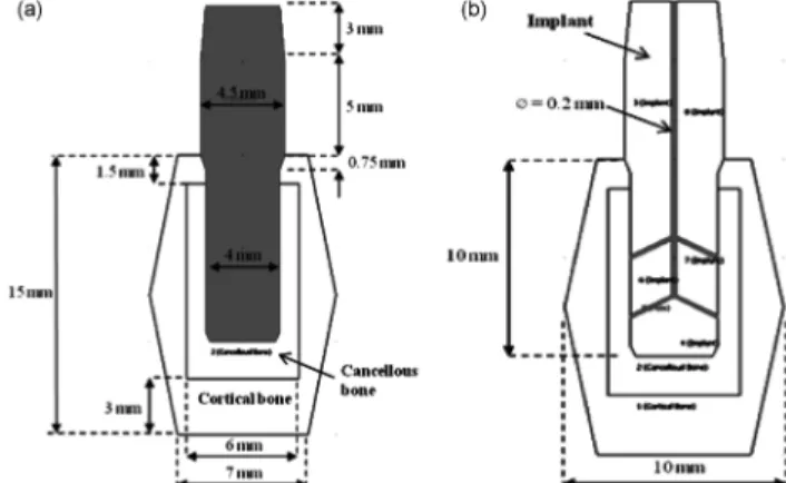
The geometric configuration of a basic 2D model of an implant fixture and the mandible arch was based on the COMSOL’s library (Fig. 1(a)). The material properties of the material used in the FE analysis were also based on the COMSOL’s library (Table 1).
The implant is cylindrical without thread to focus on the effect of placing holes with various configurations.
Fig. 1 shows the cross sectional view of implants and mandible with dimensions constructed in COMSOL. For simplicity’s sake, the contour of the cortical bone was linearly modeled. Fig. 1(b) illustrates holes in an implant with a diameter of 0.2 mm.
The opening of the hole vertically placed at the center will be used as an inlet for bioactive material and the other openings as outlets when the holes are used to inject Fig. 1. (a) Geometric configurations of cross sections of implants and mandible, (b) Geometric configurations of holes in an implant with a diameter of 0.2 mm.
Table 1. Mechanical properties of the material.
Young’s Modulus (GPa)
Poisson’s ratio
Cortical bone 20 0.3
Cancellous bone 2 0.2
Implant fixture (Titanium
Beta-215) 105 0.33
Cortical and cancellous bone
compound filling holes 14 0.27
bioactive material into the mandible hollow.
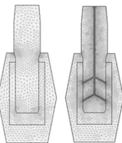
Triangular elements were used to make a mesh, and corner areas had dense elements for more accurate analysis. Models consisted of 2224 triangular elements for a basic implant and 9,856 elements for an implant with one inlet and four outlets.
Titanium beta-215 was used to model an implant fixture (Table 1). We assumed after bioactive material was applied bone grew and filled the holes if bioactive material was absorbed and leaved hollow. In this case the bone filled the holes was assumed to be compound of both cortical and cancellous bones. Since this situation was not reported yet, the mechanical property of this compound was deter- mined by the surface ratio of cortical and cancellous bones.
Load applied in the analysis was 400 N/m downward and 75 N/m right, which was a bit greater than what is usually applied in a real patient. The load was set to be evenly distributed in the upper part of the implants.
Static analysis was undertaken, in which load and con- straints were not changed with time, and the maximum value of the von Mises stress was extracted. Each stress value represented load per area and was consisted of three vertical stresses and three shear stresses.
(1) where, σ
υ= von Mises stress
σ
ii= vertical stress σ
ij= shear stress
COMSOL FEM solver solves the following differential equations for stationary case:
(2) where, σ = stress tensor
F = body forces
(3)
Eq. 2 is same as Eq. 3 with x, y, and z notation. Since 2D analysis was undertaken in this study, all z components were ignored:
σz = τ
xz= τ
yz= F
z= 0 (4)
3. Results and Discussion
Stress on an implant was examined before making holes for injecting bioactive materials such as bone morpho- genetic protein (BMP). In Fig. 3(a) the maximum stress concentration occurred at the top of buried part of the implant at the maximum load. The stress characteristics along the vertical red line were extracted in Fig. 3(b).
Stress concentration occurred at the left corner and both horizontal ends of cortical bone. The stress occurred at the left corner was attributed to the load applied to down and right direction, and interpreted as a counteraction of the applied load. The stress occurred at both horizontal ends of cortical bone showed that the load was transferred to the next tooth. It should be noted that this load transfer could be overestimated to some degree due to the cortical bone’s linear outline. Based on this result we concluded that it was desirable not to place holes at the upper part of the buried implant. Accordingly, we placed one inlet at
συ (σ11–σ22)2+(σ22–σ33)2+(σ11–σ33)2+6 σ( 122 +σ232 +σ312) ---2
=
σ1–σ2
( )2+(σ2–σ3)2+(σ1–σ3)2
---2
=
∇
– ⋅σ = F
∂σx ---∂x ∂τxy
---∂y
– ∂τxz
---∂z –
– = Fx
∂τxy ---∂x ∂σy
---∂y
– ∂τyz
---∂z –
– = Fy
∂τxz ---∂x ∂τyz
---∂y
– ∂σz
---∂z –
– = Fz
Fig. 2. Mesh Generation: 2224 triangular elements for 3 components and 9856 triangular elements for 4 components including grooves.
Fig. 3. (a) Type 0-A, Stress graph on the cross section (showing with
Red line) and (b) The stress characteristics along the vertical red line.
the top of the implant and four outlets, two per each side, and connected them with five holes as shown in Fig. 1(b).
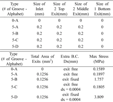
These holes were filled with bone compound in the next bone growth progress, but the compound was not con- nected with the mandible yet since we assumed that the bioactive material was not completely consumed. The result showed that the maximum stress increased to 0.1807 MPa, which was 14% higher than that of without the holes (Fig. 4). There was no significant change in stress distribution (Fig. 5).
In the next bone growth progress the bone compound in the holes was assumed to be connected with the man- dible through the four outlets and thus the bone compound elements in the model were assigned to be fixed boundary condition. Furthermore, bioactive material coated the im- plant at this stage. Fig. 6 shows the stress concentration was disappeared from the implant and the mandible
except four outlets. This suggested that the bone com- pound and the coating layer played an important role in the stress characteristics within the implant, cancellous and cortical bone.
8)However the maximum stress elevated from 0.1807 MPa to 1.757 MPa.
More obvious results were expected by assuming loose implants in order to check the actual reinforcing effects of bioactive materials. To give conditions of loose implants, the displacement was given to the implant as an X-direction boundary condition in the same direction the load applied to, and the case to act as a reinforcer at the outlet was compared with not the case. In fact, since cortical bones have 10 times higher strength than can- cellous bones, it is highly probable that the displacement occurs in cancellous bones. Assuming that the displace- ment to the implant in cancellous bones was 0.0004 mm in the X direction (the maximum stress of 0.1805 MPa was almost the same value of 0.1879 MPa without the displacement shown in Fig. 5, namely to meet the very small displacement conditions), in the case not to act as a reinforcer at the outlet, no constraint was given to the contact area of the outlet (free), and in the case to act as a reinforcer at the outlet, the contact area of the outlet was fixed (fixed). Both cases were compared.
Boundary Conditions:
On the top of Implant Loading
Fy = −400 N/m Fx = 75 N/m
At the boundary of implant contact Cancellous bone Dx = 4e-6 m
Fig. 7 shows a picture of the stress contour in the case Fig. 4. Type 0-A, Stress contour with deformation and displacement
contour with no design change (Max. Stress = 0.1589 MPa, Max.
Displacement = 3.156e-5 m).
Fig. 5. Type 5-A, Stress Contour with groove for BMP (Max. Stress
= 0.1807 MPa. Dia. of groove = 0.2 mm).
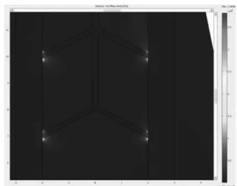
Fig. 6. Type 5-B, Stress Contour with groove for BMP (Max.
Stress = 1.757 MPa. Dia. of groove = 0.2 mm).
not to act as a reinforcer at the outlet with a new Boundary Condition of 0.004 mm X-direction displacement. Given the results of a new displacement in the X direction, the part shown in the red circle at the top-left corner in the contact area of the implant and the cortical bones indicates the occurrence of a new stress concentration. When the displacement occurs in cancellous bones, it is found that the stress concentration occurs at the implanting part of the implant.
After bioactive materials were injected with a single in- jection hole and four outlet holes, the implant surface coating was formed after a certain period and the bones with cancellous and cortical elements were grown up through outlet holes.
11)And the reinforcing effects of the implant bonding through four outlet holes occurred, then the Boundary Condition of fixed outlet holes can be given.
In the case for the bioactive materials to act as a rein- forcer, all the stress concentration effects were dramatically relieved not only at the implant but also at each contact
area even with the displacement (Fig. 8). This was similar to the case without the consideration of displacement effects (Fig. 6). Fig. 9 can also confirm that the stress decreases rapidly from the maximum stress concentration point in contrast with what the stress decreased slowly before.
10)While the bad news is that the relieved stresses across the implant were concentrated to four outlets, and the maximum stress concentration increased 21 times (0.1805 MPa → 3.809 MPa) compared to the case without bio- active material effects. The possibility of the rupture at the outlet has been rather increased (Fig. 10). This value is twice higher than the value of Fig. 6 cases (1.757 MPa) without the consideration of displacement effects.
Of course, considering that the X-direction displacement was given in order to assume loose implants, as shown before, 9.7 times value of the maximum stress value was calculated.
The results of analyses for the reinforcing effects con- sidering with or without the displacement using Finite Element Method are summarized in the table below.
Thus, the design improvement is necessary to reduce Fig. 7. Type 5-C, Stress contour and deformation shape for 5 groove
without bonding effect (Dia. of groove = 0.2 mm Max. Stress = 1.805e5 Pa).
Fig. 8. Type 5-D, Stress contour for 5 groove with bonding effect (Dia. of groove = 0.2 mm Max. Stress = 3.809 MPa, Max Displace- ment = 2.43e-5 m).
Fig. 9. Type 5-D, Stress Graph on the Cross Section.
Fig. 10. Type 5-D, Stress contour zooming at 4 exits.
stresses concentrated on four outlets. Typically, assuming that a uniform stress distribution in the cross-sectional area, the mean stress ( σ) is proportional to the vertical load (F) and inversely proportional to the cross-sectional area (A).
In other words,
σ = F/A (5) Accordingly, in order to reduce stress, the cross-sectional area should be increased under the same load and if the cross-sectional area is fixed, the stress or the stress con- centration can be reduced by changing the position or angle of the load concentration. By employing the fol- lowing two methods, better injection/outlet hole design can be developed.
1. Increase the contact area of the implant and the cancellous bones by increasing the size and the number of outlet holes.
2. Relieve stress concentration by changing the shape or location of outlet holes.
4. Conclusion
A simplified 2D model is proposed in this study to examine the effect of the properties of holes inside an implant and the interface layer formed with bioactive materials injected through the holes on stress distribution within the mandible and the implant. It was found that when bioactive materials formed an interface layer between the implant and the mandible and the four holes were filled with the cortical and cancellous bones all the stress
concentrated opposite to loading side without holes disap- peared. The stresses at four outlets of hole mildly elevated but the maximum stress value increased ten times com- pared with the value without bioactive material.
In addition, as a result of analyzing bioactive material injection effects considering the very small displacement in the cancellous bones, it is confirmed that the stress con- centration spread across the implant gathered to four outlets and the maximum stress increased over 20 times compared to the case before the bioactive material injection.
As a result, it is confirmed that the stress concentration spread throughout all the implant with or without the dis- placement relieved by injecting bioactive materials. How- ever, the design optimization is necessary to reduce stresses concentrated on the very small area of outlets by increasing the size and the number of outlet holes or by changing the shape or location of outlet holes.
3D design optimization will be done based on the first phase basic study results and a first design model will be presented through additional fatigue tests. In addition, the future research direction is to build the Implant Simu- lation Model applicable to various implant designs by applying the strengthening process of bioactive materials with animal experiments and clinical data using Multi- physics Transient solution.
Acknowledgement
This study was financially supported by Seoul National University of Science & Technology.
References
1. P. I. Branemark, J. Prosthet. Dent., 50, 399 (1983).
2. P. I. Branemark, U. Breine, R. Adell, B. O. Hansson, J.
Lindstrom and A. Ohlsson, Scand. J. Plast. Reconstr.
Surg. Hand Surg., 3, 81 (1969).
3. L. A. Weinberg and B. Kruger, Oral Surg. Oral Med.
Oral Pathol., 78, 22 (1994).
4. D. C. Holmes, W. R. Grigsby, V. K. Goel and J. C.
Keller, Int. J. Oral. Maxillofac. Implants, 7, 450 (1992).
5. B. Rangert, T. Jemt and L. Jorneus, Int. J. Oral. Maxillofac.
Implants, 4, 241 (1989).
6. E. J. Richter, J. Prosthet. Dent., 61, 602 (1989).
7. I. P. Van Rossen, L. H. Braak, C. de Putter and K. de Groot, J. Prosthet. Dent., 64, 198 (1990).
8. M. Quirynen, N. Van Assche, D. Botticelli and T.
Berglundh, Int. J. Oral. Maxillofac. Implants, 22, 203 (2007).
9. R. Crespi, P. Capparé, E. Gherlone and G. E. Romanos, Int. J. Oral. Maxillofac. Implants, 23, 753 (2008).
10. R. Palmer, J. Evid. Base. Dent. Pract., 7, 8 (2007).
11. Y. M. Im, J. I. Choi, D. Khang and T. H. Nam, Kor. J.
Mater. Res., 22(2), 66 (2012) (in Korean).