*교신저자: 이이규규복복
700-721 대구광역시 중구 삼덕2가 188-1번지 경북대학교 치과병원 6층 치과보철과 053-600-7651: e-mail, kblee@knu.ac.kr 원고접수일: 2009년 6월 19일 / 원고최종수정일: 2009년 9월 14일 / 원고채택일: 2009년 9월 15일
서론
변연골의 점진적 소실은 임플란트 식립후 흔히 관찰되 는 현상이다. 변연골 소실의 기구로는 몇가지 인자가 제 시되고 있는데 대표적으로 미생물에 의한 임플란트 주 위염1-3과 생리범위를 벗어나는 하중 작용4이 거론되어 왔 다. 골소실은 변연골에서 개시하여 점차 하방으로 전진 하는데, 골소실이 수직적으로 일어나 치조정골이 분화 구 (crater) 형상으로 변화하면 변연골 응력집중이 완화되 어 응력이 오히려 낮아지는 긍정적 효과도 있다.5,6그러 나 장기적으로는 포켓이 깊어져 감염 소지가 커지는 등 생물학적으로 불리한 환경이 조성될 수 있다.
과도한 힘과 변연골 소실과의 유의한 상관관계는 임상 연구7-9나 동물실험10-12결과로 입증되고 있으며, 그 배후는 변연골에 유발되는 응력집중현상일 것임을 보여주는 유 한요소해석 결과가 제시되고 있다.10,13-15실제, 변연골에서 의 응력집중은 임플란트 크기나 형상,16,17임플란트/골 계 면의 골유착 조건,18-20악골 폭경21등 해부학적 조건, 하중 방향22등의 다양한 변수와 무관하게 항상 관찰되었다. 이 러한 결과는 임플란트의 장기적인 기능유지와 관련하여 변연골, 즉 임플란트 경부를 둘러싸는 치밀골의 응력에 대한 파악과 관리가 필요함을 시사해 준다.
국내외에서 다양한 디자인의 임플란트가 출시되고 있
다. 임플란트의 디자인은 재질, 표면특성과 더불어 골응 력에 중요한 영향을 미치므로, 치료 목적에 합당한 임플 란트의 선정을 위해서는 역학적 관점에서 임플란트 디 자인에 대한 이해가 필요할 것이다. 임플란트 몸체는 물 론 경부의 디자인이 중요할 것으로 보이는데, 그 이유는 이 부위는 변연골에 근접하여 있으므로 그 응력에 직접 적인 영향을 줄 수 있기 때문이다. 그러나 이전의 대부분 의 생역학적 연구는 고정체 몸체의 디자인, 즉 그 크기나 나사산 형상 등에 초점을 두고 있었다.13,23-30이에 본 연구 에서는 임플란트 경부 디자인, 특히 지대주 체결 양식이 골응력에 미치는 영향에 대해 분석하고자 한다.
연구재료 및 방법
본 연구에서는 지대주 체결 방식에 따라 external형,
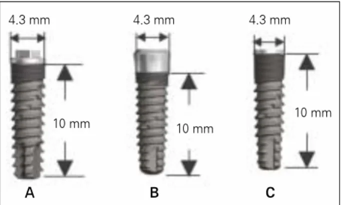
internal형 및 submerged형으로 구분되는 3종의 임플란트 ((주)덴티스, 대구, 대한민국)를 해석 모델로 선정하였다 (Fig. 1). 3 종류 임플란트 모두 매식부의 길이는 10 mm, 경
부의 직경은 4.3 mm이다.1. 축대칭 유한요소 모델 (Axisymmetric FE Modelling) 임플란트가 식립된 악골에 대한 전형적인 축대칭 유한
유한요소법을 이용한 임플란트 경부 디자인이 골응력에 미치는 영향 분석
김경탁1∙조광헌2∙이청희2∙유원재3∙이규복4*
경북대학교 치의학전문대학원 치과보철학교실1대학원생, 2교수, 4부교수 경북대학교 치의학전문대학원 치과교정학교실3부교수
연구목적: 임플란트 경부 디자인의 차이가 경부 치밀골의 응력분포에 미치는 영향을 유한요소법을 이용하여 분석하고자 한다.
연구재료 및 방법: 몸체 형상은 유사 (직경 4.3 mm, 길이 10 mm)하나 경부 디자인이 internal형, external형, 및 submerged형으로 다른 3종의 임플란트 시스템 ((주)덴티스, 대구, 대한민국)에 대하여 축대칭 유한요소모델을 사용하여 해석하였다. 악골 폭경은 7 mm로 동일하게 모델링하였고 하중 조건으로는 임플란 트 장축에 평행한 수직하중 50 N, 임플란트 장축에 45�방향으로 작용하는 경사력 50 N을 설정하였다.
결과: 해석한 3종의 임플란트 모두 경부 피질골에 응력집중을 발생시켰으며 디자인 차이에 따른 응력 수준의 차이가 관찰되었다. 경부 피질골의 최대 응력 은 수직력 조건에서 internal형, submerged형, external형의 순으로 컸으며, 그 값은 각각 2.71, 2.60, 2.48 MPa였다. 경사력 조건에서는 internal형, external형, sub- merged형의 순으로 컸으며 그 값은 각각 9.30, 9.14, 8.97 MPa였다.
결론: 임플란트 경부 디자인이 주위 치밀골의 응력 분포에 영향을 미칠 수 있지만 그 차이는 크지 않은 것으로 분석되었다. (대한치과보철학회지 2009;47:
385-93)
주요단어: 임플란트 지대주, 경부 디자인, 유한요소, 응력, 수직력, 경사력
요소 모델을 Fig. 2에 나타내었다. 악골은 동일한 형상조 건을 부여하여 골조건 차이가 응력에 미치는 영향을 배 제하였다. 좁은 폭경의 악골에서 테이퍼 효과에 의한 경 부골의 응력감소가 관찰된 것으로 보고한 Chang21의 연 구를 참조하여, 악골 폭경은 임플란트 첫 번째 나사부위 에서 7 mm로 하였고 근첨부로 가면서 약간씩 증가하는 형상으로 모델링하였다.
임플란트 경부골은 임플란트 장축과 근원심으로는
90�
를 이루며, 협설 방향에서는 경사각을 갖는다. 이러한3차원 형상을 축대칭 모델링에 적절히 반영하기 위해, 근
원심 방향과 협설 방향의 임의 단면으로부터 가상적인 평균 곡률을 추론하였고 이를 spline 곡선에 반영하여 굴 곡 없이 자연스런 형상이 되도록 모델링하였다. 모든 모 델링과 해석에는 NISA II/Display III (EMRC, Troy, MI,USA) 프로그램을 사용하였다.
골질은 장21의 연구를 참조하여 Lekholm과 Zarb31에 의 한 분류 중 type II 골을 가정하였고, 치밀골의 두께는 0.75
mm로 설정하였다. 연조직의 경우 그 하중분담률을 무시
할 수 있으므로 해석 전반에 걸쳐 모델링에서 제외하였 다.유한요소 mesh 구성에는 NISA II의 NKTP type 34형
solid 요소 (4각형 axisymmetric 요소, 요소당 절점수 8개)
를 사용하였다. 이 요소는 축대칭 구조의 모델링에 사용되지만 축대칭인 수직하중은 물론 비축대칭형 하중조건 에 대해 해석할 수 있으며, 이론적 배경은 Park22과 Asaoka 등32의 논문을 참조할 수 있다.
수치해석의 오차를 감소시키기 위한 방안으로 대부분 의 요소에 대해 종횡비 (aspect ratio)는 5.0이내로, 또 요소 의 corner각을 45 - 135�범위로 제한하였으나 나사산 주위 등 형상변화가 큰 일부 부위에서는 이를 만족시킬 수 없 었다. 응력의 변화가 비교적 급격할 것으로 예상되는 나 사산 주위와 고정체의 경부 및 첨부 (apex)에서는 세분화 된 mesh를 사용하였고, 응력변화가 완만할 것으로 예상 되는 부위에서는 큰 (coarse) mesh를 사용하여 계산량을 절감하였다 (Fig. 2). 모델별로 차이가 있으나 각 모델은
3,200개 내외의 요소와 약 10,500개의 절점으로 구성되었
다. 악골은 임플란트 고정체 길이의 1.5배 높이를 모델링 에 포함시켰다.2. 재료 물성 (Material properties)
해석에 포함된 모든 재질에 대하여 선형탄성 물성을 가정하였다. Table I에는 여러 선학들의 자료를 참조하여 본 연구에 적용한 골 및 금속 재료의 물성치를 나타내었 다.20-22
Fig. 1. Design configuration of 3 implants; A: external type, B: internal type, C: submerged type.
Table I. Mechanical properties (bone and implant materials)
Material Young Modulus (GPa) Poisson ratio Strength (MPa) Tensile yield stress (MPa)
Titanium 102.2 0.35 - -
Cortical bone 13.7 0.3 72 - 76 (tensile) 60
140 - 170 (compressive)
Cancellous bone 1.37 0.3 22 - 28 (tensile) -
Gold (type 4) 95 0.3 -
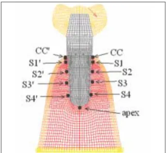
Fig. 2. Coordinate system and typical axisymmetric finite element model of the implant/bone complex sub- ject to a load of 50 N acting at 45 degree with the implant axis. Soft tissues are not included in the F. E.
model.
A B C
10 mm 10 mm
10 mm
3. 하중/경계조건 및 응력관찰점
상용저작하중 크기가 15 - 50 N 정도임을 감안,33,34본 연 구에서는 임플란트 장축에 평행한 수직하중 50 N과 임플 란트 장축에 45�방향으로 작용하는 경사력 50 N의 하중 조건을 설정하였다
하중은 치관 중앙점에서 약 1.5 mm 떨어진 위치에 부 여하였다 (Fig. 2). 변위 경계조건으로는 기저면상의 모든 절점에서 Ux = Uy = 0 조건을 부여하여, 악골 기저면이 고정된 것으로 모사하였다. Ux, Uy는 각각 x축 및 y축 방 향의 변위를 나타낸다 (Fig. 2).
골융합이 성공적으로 이루어지면 골/임플란트 계면에 는 기계적 결합 (mechanical interlocking)이 형성되므로 마 찰손실 없이 힘전달이 완전히 일어나는 것으로 가정하 여 본 연구에서는 임플란트/골 계면은 완전결합을 가정 하였다.
Fig. 3은 골응력 분포를 상호 비교를 용이하게 하기 위
하여, 임플란트 주위골의 총 11개의 node를 응력관찰점 으로 설정한 것을 나타낸 것이다. 응력관찰점은 해면골 에서는 임플란트에 가장 근접된 node로 설정하였다. 경 부에서는 임플란트와 골이 직각을 이루며 노치를 만드 는 기하학적 조건으로 인하여 특이점이 생기는 문제가 있으므로 이를 피하기 위하여 경부 피질골의 응력관찰 점은 피질골판의 중립면상에서 임플란트로부터 약 0.3mm 떨어진 지점의 node를 선정하였다.
결과
직경이 4.3 mm, 매식부 길이 10 mm 로 동일하나 경부 디자인이 다른 3 종의 임플란트 (Fig. 1)가 7 mm 폭경의 악골에 식립된 경우에 대해, 수직하중 50 N 및 임플란트 장축과 45�방향의 경사력 50 N이 작용하는 조건에 응력 을 해석하였고 그 stress plot 을 나타내었다. Fig. 4와 5는
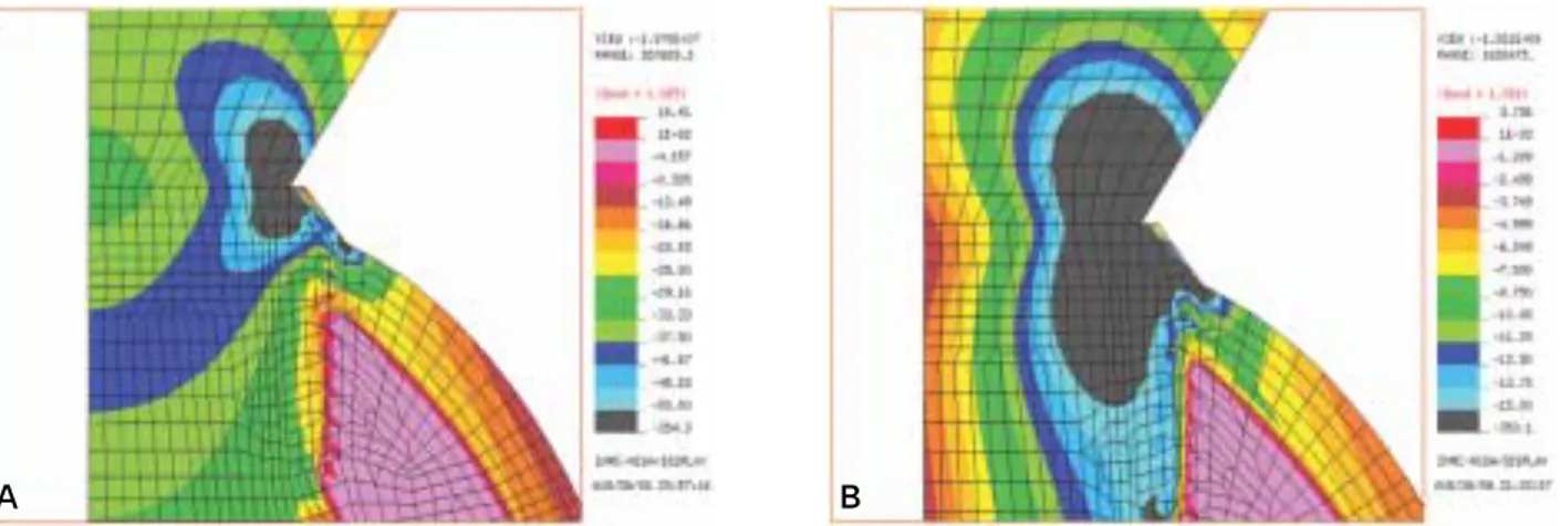
external형의 결과이다. Fig. 4 A, B는 수직력 및 경사력 조
건에서 골/임플란트 전체의 응력분포이고, Fig. 5의 A, B 는 각각의 경우에 대해 응력집중이 일어나는 경부골 부 위를 확대한 것이다.Fig. 6과 7은 각각 internal형, submerged형 임플란트에 대
한 해석 결과이다. 이 두 경우는 골/임플란트 전체 응력 분포 결과는 생략하고 경부 주위를 확대한 결과도를 제 시하였다.평가에 사용된 응력은 제 3 주응력 (principal stress III)으 로 최대압축응력을 나타낸 것이며 치조골 소실과 관련 이 깊은 것으로 간주되는 응력 요소이다. 일부 이전 연구 들에서는 골응력평가에 von Mises 응력을 사용하고 있으 나 이 요소는 소성변형을 하는 금속재료의 항복조건 산 출시 사용되는, 전단응력에 기초한 등가응력으로 골의 거동에 대한 기준이 될 수 있음을 입증한 연구사례가 없 어 보인다. 반면, 압축/인장 방향의 응력이 골흡수에 연관 됨을 보이는 연구결과가 보고되고 있고,23,24특히 압축응 력에 의한 골흡수와 인장응력에 의한 골형성 관계가 치 과교정 영역에 직접 응용되고 있으므로, 본 연구에서는 제 3 주응력을 평가응력으로 삼았다.
응력관찰점에서의 임플란트 주위골의 응력분포 비교 는, 수직하중 조건에 대한 결과는 Fig. 8에, 경사하중 조건 에 대한 결과는 Fig. 9에 각각 나타내었다. Table II는 응력 집중이 관찰되는 경부 치밀골 관찰점에서의 응력결과 비교이다.
Table II. Stresses in the crestal cortical bone
Implant type Load conditions
Vertical load (50 N) Oblique load (50 N)
External 2.48 MPa 9.14 MPa
Internal 2.71 MPa 9.30 MPa
Submerged 2.60 MPa 8.97 MPa
Fig. 3. Stress monitoring points in the bone: two points on the mid plane of cervical cortical plate, nine points in the cancellous bone.
Fig. 4. Maximum compressive stresses in the case of external type implant under: A: vertical load of 50 N, B: oblique load of 50 N.
Fig. 5. Magnification of the cervical area where the highesr stress concentration is noted: in the cases of A: vertical load, B: oblique load.
Fig. 6. Magnification of the cervical of the internal type implant subject to : A: vertical load of 50 N, B: oblique load of 50 N.
A B
A B
A B
고찰
골응력의 감소를 위해서는 일차적으로 임플란트 표면 적이 커야 하므로 해부학적 환경이 허용하는 범위에서 가급적 길고 직경이 큰 임플란트를 사용해야 한다. 임플 란트 변연골의 높은 응력은 임플란트와 치조정골이 만 나며 이루는 노치에 의해 응력집중이 생기며 일어나는 현상이므로 임플란트 크기에 비례한 산술적 감소가 이 루어 지지 않으므로 주의가 필요하다.35일례로, 직경이 크면 임플란트 면적 증대로 인한 산술적인 응력 감소 이 상의 효과가 있었다.16
본 연구에서는 임플란트 지대주 디자인이 경부골 응력 분포에 미치는 영향을 비교하였다. 악골 폭경을 7 mm로 설정하여, 직경 4.3 mm, 길이 10 mm인 3종의 임플란트 주 위골 응력분포 해석을 수행하였다. 수직력 50 N 조건하 에서는 임플란트 근첨부 망상골에서 응력이 0.7 MPa내
외로, 약간의 응력집중이 관찰된다. 이를 제외한 전체 망 상골에서 응력 값은 3종의 임플란트 모델에 있어서 비교 적 균일한 분포를 보인다. 망상골 응력은 임플란트 경부 디자인에 유의한 영향은 받지 않으며, 또한 나사산 주위 골의 응력은 낮고 비교적 균일하여 생역학적으로 문제 소지는 없는 것으로 평가되었다 (Fig. 8) .
경부 디자인의 차이나 힘의 방향에 무관하게 경부골에 서는 높은 응력집중이 관찰되었으며, 이는 이전의 연구 결과들과 일치한다.10-22수직력하에서 경부 치밀골의 최 대 응력은 임플란트 모델에 따라 2.48 - 2.71 MPa로 약간 의 차이가 관찰되었다.
경사력 조건은 저작압이 임플란트 축에 경사되어 작용 하여 임플란트가 측방력을 받는 경우에 대한 해석이며, 이 조건은 상하 치열간 근원심 방향의 교두간섭이 생기 거나, 순(협)설 방향의 교합조정이 불완전한 경우에 생길 수 있다. 이 경우 측방력은 굽힘응력을 유도하게 되므로, Fig. 7. Magnification of the cervical of the submerged type implant subject to : A: vertical load of 50 N, B: oblique load of 50 N.
A B
Fig. 8. Stresses recorded at the 11 stress monitoring points under vertical load condition (50 N).
Fig. 9. Stresses recorded at the 11 stress monitoring points under oblique load condition (50 N).
에서 경부치밀골에 가장 큰 응력이 관찰되었으며 그 크 기는 8.97 - 9.3 MPa내외였다. 하중작용 방향의 반대측
(Fig. 3 의 응력관찰점 CC’ , S1’ , S2’ , S3’ , S4)에서는 굽힘
응력이 수직력에 의한 압축응력이 상쇄하게 되므로 압 축응력이 감소하였다 (Fig. 9) .Fig. 4에서 볼 수 있는 바와 같이 수직하중 및 경사하중
조건 모두에서 경부 치밀골에서 반경 약 0.2 - 0.4 mm 내 에 응력이 극히 집중되어 있는 형상을 관찰되었다. 본고 에서 제시하지는 않았으나 internal형 및 external형 임플란 트의 경우에도 동일한 현상이 관찰되었다. 이 부위를 확 대한 Fig. 5, 6, 7에서 보는 바와 같이 지대주 차이에 따라 응력 분포가 차이가 있었다. 측방력 하에서는 submerged 형 모델의 경우에서 가장 낮은 응력이 발생되었다.응력이 과도하다면 골개조에 문제를 일으켜 골융합에 장애를 줄 수 있다. 골생리 이론에서는 스트레인을 그 척 도로 삼고 있는데, Frost36는 응력에 의해 골이 과도하게 변형되면 임플란트와 골계면간의 긴밀한 관계를 유지할 수 없다고 하였으며 4,000 μ
-strain 이상의 부하는 병리적
변화를 일으킬 가능성이 있고, 25,000 μ-strain 이상에서는
골괴사/미세골균열을 야기할 수 있다고 하였다. Meyer 등37은 반복되는 4,000 μ-strain 이상 스트레인에서는 임플
란트와 골조직간에 섬유성 조직이 게재되고 최대200,000 μ -strain 이상에서는 콜라겐 배열에 이상이 온다고
하였다. Hansson과 Werke38는 골조직에 응력이 과도하면 골흡수가 생기며 Isidor39는 6,700 μ
-strain 이상에서 임플란
트 주위에서 골흡수가 일어난다고 하였다. 이상의 연구 결과로부터 치조골 골개형에 장애를 주지 않는 생리적 스트레인 범위를 4000 μ-strain 정도로 추산하고, 이를 피
질골 (E = 13.7 GPa, Table I) 압축응력으로 환산하면 이는55 MPa 정도이다. 이 역치수준을 넘어가는 응력수준에
서는 임플란트는 변연골의 점진적 흡수로 인해 안정성 이 감소하게 될 것이다.본 연구에서는 임플란트 경부 디자인 차이에 따라 경 부치밀골에 응력분포에 차이가 생김을 관찰하였다. 그 러나 응력 자체의 크기는 경사력의 경우에도 10 MPa 이 내였으며 임플란트 모델간의 차이는 0.33 MPa 로 미미하 였고 수직하중하에서 차이는 더 작았다. 즉, 경부골 응력 의 역치를 55 MPa 로 가정한다면 경부 디자인에 의한 골 응력 차이는 무시할 수 있을 것으로 보인다.
한편, 본연구의 응력 비교는 임플란트 경부 디자인 차 이에 대한 정성적인 상대 평가이므로 그 결과로부터 경 부골 흡수가 없을 것으로 예단할 수 없다. 경부 치밀골의
과 경부 치밀골이 점촉하여 노치를 이루는 부위, 즉 임플 란트에 더 가까운 치밀골의 외곽에서는 이 위치보다 응 력이 더욱 커질 수 있으며, 힘의 크기와 경사각이 커 진다 면 응력은 더욱 증대될 것이다.
결론
경부 디자인이 다른 3 종류의 임플란트 (external형,
internal형 및 submerged형) 모델에 대하여 유한요소해석
을 수행하였다. 수직력 50 N과 경사력 50 N의 하중조건 하에서 임플란트/골 계면에서 완전한 골유착이 일어난 경우를 가정하여 경부 치밀골의 최대압축응력을 비교하 였다. 본 해석을 통해 얻은 결과를 분석하여 다음의 결론 을 도출하였다.1. 응력의 최대값은 모든 임플란트에 대해서 경부골에
서 발생하였다. 수직력 50 N 조건에서 각 모델 경부 피질골의 최대 응력은 internal형, submerged형,external형의 순으로 컸으며, 그 값은 각각 2.71, 2.60, 2.48 MPa였다.
2. 경사력 하에서는 경부 피질골의 최대응력은 internal
형, external형, submerged형의 순으로 컸으며 그 값은 각각 9.30, 9.14, 8.97 MPa였다.3. 두 하중 조건 모두에서 임플란트 경부디자인이 응력
에 미치는 영향은 크지 않은 것으로 분석되었다.참고문헌
1. Becker W, Becker BE, Newman MG, Nyman S. Clinical and microbiologic findings that may contribute to dental implant failure. Int J Oral Maxillofac Implants 1990;5:31-8.
2. Lindhe J, Berglundh T, Ericsson I, Liljenberg B, Marinello C. Experimental breakdown of peri-implant and periodon- tal tissues. A study in the beagle dog. Clin Oral Implants Res 1992;3:9-16.
3. Schou S, Holmstrup P, Reibel J, Juhl M, Hj
�
rting-Hansen E, Kornman KS. Ligature-induced marginal inflammation around osseointegrated implants and ankylosed teeth: stere- ologic and histologic observations in cynomolgus monkeys (Macaca fascicularis). J Periodontol 1993;64:529-37.4. Vaillancourt H, Pilliar RM, McCammond D. Factors af- fecting crestal bone loss with dental implants partially cov- ered with a porous coating: a finite element analysis. Int J Oral Maxillofac Implants 1996;11:351-9.
5. Jung ES, Jo KH, Lee CH. A finite element stress analysis of the bone around implant following cervical bone resorp-
tion, J Korean Acad Implant Dent 2003;22:38-47.
6. Kitamura E, Stegaroiu R, Nomura S, Miyakawa O.
Influence of marginal bone resorption on stress around an implant - a three - dimensional finite element analysis. J Oral Rehabil 2005; 32:279-86.
7. Adell R, Lekholm U, Rockler B, Bra�nemark PI, Lindhe J, Eriksson B, Sbordone L. Marginal tissue reactions at os- seointegrated titanium fixtures (I). A 3-year longitudinal prospective study. Int J Oral Maxillofac Surg 1986;15:39- 52.
8. Jemt T, Lekholm U, Adell R. Osseointegrated implants in the treatment of partially edentulous patients: a preliminary study on 876 consecutively placed fixtures. Int J Oral Maxillofac Implants 1989;4:211-7.
9. Quirynen M, Naert I, van Steenberghe D. Fixture design and overload influence marginal bone loss and fixture suc- cess in the Bra�nemark system. Clin Oral Implants Res 1992;3:104-11.
10. Hoshaw SJ, Brunski JB, Cochran GVB. Mechanical load- ing of Bra�nemark implants affects interfacial bone model- ing and remodeling. Int J Oral & Maxillofac Implants 1994;9:345-60.
11. Isidor F. Loss of osseointegration caused by occlusal load of oral implants. A clinical and radiographic study in mon- keys. Clin Oral Implants Res 1996;7:143-52.
12. Isidor F. Histological evaluation of peri-implant bone at im- plants subjected to occlusal overload or plaque accumula- tion. Clin Oral Implants Res 1997;8:1-9.
13. Holmgren EP, Seckinger RJ, Kilgren LM, Mante F.
Evaluating parameters of osseointegrated dental implants using finite element analysis--a two-dimensional compara- tive study examining the effects of implant diameter, im- plant shape, and load direction. J Oral Implantol 1998;
24:80-8.
14. Van Oosterwyck H, Duyck J, Vander Sloten J, Van der Perre G, De Cooman M, Lievens S, Puers R, Naert I. The influence of bone mechanical properties and implant fixa- tion upon bone loading around oral implants. Clin Oral Implants Res 1998;9:407-18.
15. O’Mahony AM, Williams JL, Spencer P. Anisotropic elas- ticity of cortical and cancellous bone in the posterior mandible increases peri-implant stress and strain under oblique loading. Clin Oral Implants Res 2001;12:648-57.
16. Kum YJ. Finite Element Analysis of the Influences of the Implant Diameter on the Cortical Bone Stresses. MD the- sis, Department of Dentistry, Kyungpook Nat Univ 2004.
17. Lim JY, Lee CH, Jo KH. A Finite Element Stress Analysis of the Bone aroung Implant following the Shape of Root Form Implant. J Korean Acad Implant Dent 2003;22:25- 37.
18. Lee JW, Lee CH, Jo KH. Finite element analysis of the stress distribution with load transfer characteristics of the implant/bone interface. J Korean Acad Implant Dent 2003;
22:49-56.
19. Lee SH. Stress analysis with nonlinear modelling of the load transfer characteristics across the osseointegrated inter- faces of dental implant. MD thesis, Department of Dentistry, Kyungpook Nat Univ 2002.
20. Cha SB. Finite element approach to investigate the influ- ence of the design configuration of the ITI solid implant on the bone stresses during the osseointegration process. MD thesis, Department of Dentistry, Kyungpook Nat Univ 2005.
21. Chang JM. Finite Element Approach to Investigate the Influence of the Jaw Bone Dimension on the Stresses Around the Root Analogue Dental Implant. MD thesis, Department of Dentistry, Kyungpook Nat Univ 2004.
22. Park DY. Three dimensional Stress Analysis Around Osseointegrated Bra�nemark Implant System Using An Axisymmetric Modelling Approach. MD Thesis, Kyungpook Nat Univ 2001.
23. Matsushita Y, Kitoh M, Mizuta K, Ikeda H, Suetsugu T.
Two-dimensional FEM analysis of hydroxyapatite im- plants: diameter effects on stress distribution. J Oral Implantol 1990;16:6-11.
24. Meijer HJ, Kuiper JH, Starmans FJ, Bosman F. Stress dis- tribution around dental implants: influence of superstruc- ture, length of implants, and height of mandible. J Prosthet Dent 1992;68:96-102.
25. Duyck J, Naert IE, Van Oosterwyck H, Van der Sloten J, De Cooman M, Lievens S, Puers B. Biomechanics of oral implants: a review of the literature. Technol Health Care 1997;5:253-73.
26. Palmer RM, Smith BJ, Palmer PJ, Floyd PD. A prospec- tive study of Astra single tooth implants. Clin Oral Implants Res 1997;8:173-9.
27. Nordin T, Jo¨nsson G, Nelvig P, Rasmusson L. The use of a conical fixture design for fixed partial prostheses. A prelim- inary report. Clin Oral Implants Res 1998;9:343-7.
28. Norton MR. Marginal bone levels at single tooth implants with a conical fixture design. The influence of surface macro - and microstructure. Clin Oral Implants Res 1998;9:91-9.
29. Chun HJ, Cheong SY, Han JH, Heo SJ, Chung JP, Rhyu IC, Choi YC, Baik HK, Ku Y, Kim MH. Evaluation of de- sign parameters of osseointegrated dental implants using fi- nite element analysis. J Oral Rehabil 2002;29:565-74.
30. Tada S, Stegaroiu R, Kitamura E, Miyakawa O, Kusakari H. Influence of implant design and bone quality on stress/strain distribution in bone around implants: a 3-di- mensional finite element analysis. Int J Oral Maxillofac Implants 2003;18:357-68.
31. Lekholm U, Zarb GA. Patient selection and preparation. In:
Bra�nemark PI, Zarb GA, Albrektsson T, eds. Tissue-inte- grated prostheses: osseointegration in clinical dentistry.
Chicago: Quintessence; 1985,199-209.
nium for dental implants. J Biomed Mater Res 1985;19:699-713.
33. Papavasiliou G, Kamposiora P, Bayne SC, Felton DA.
Three-dimensional finite element analysis of stress-distrib- ution around single tooth implants as a function of bony support, prosthesis type, and loading during function. J Prosthet Dent 1996;76:633-40.
34. Richter EJ. In vivo vertical forces on implants. Int J Oral Maxillofac Implants 1995;10:99-108.
35. Yu W, Jang YJ, Kyung HM. Combined influence of im- plant diameter and alveolar ridge width on crestal bone stress: a quantitative approach. Int J Oral Maxillofac
2003;275A:1081-101.
37. Meyer U, Joos U, Mythili J, Stamm, T, Hohoff A, Stratmann U, Wiesmann HP. Ultrastructural characteriza- tion of the implant/bone interface of immediately loaded dental implants. Biometerials 2004;25:1959-67.
38. Hansson S, Werke M. The implant thread as a retention el- ement in cortical bone: the effect of thread size and thread profile: a finite element study. J Biomech 2003;36:1247-58.
39. Isidor F. Loss of osseointegration caused by occlusal load of oral implants. A clinical and radiographic study in mon- keys. Clin Oral Impl Res 1996;7:143-52.
Cervical design effect of dental implant on stress distribution in crestal cortical bone studied by finite element analysis
Kyung Tak Kim1, DDS, Kwang-Heon Jo2, DDS, MSD, PhD, Cheong-Hee Lee2, DDS, MSD, PhD, Wonjae Yu3, DDS, MS, PhD, Kyu-Bok Lee4*, DDS, MSD, PhD
1
Graduate Student,
2Professor,
4Associate Professor, Department of Prosthodontics, School of Dentistry, Kyungpook National University
3
Associate Professor, Department of Orthodontics, School of Dentistry, Kyungpook National University
Statement of problem: High stress concentration on the crestal cortical bone has been regraded as a major etiologic factor jeopardizing long term stability of endosseous implants. Purpose: To investigate if the design characteristics of crestal module, i.e. internal type, external type, and submerged type, affect stress distribution on the crestal corti- cal bone. Material and methods: A cylindrical shaped implant, 4.3 mm in diameter and 10 mm in length, with 3 different crestal modules, i.e. internal type, external type, and submerged type, were analysed. An axisymmetric scheme was used for finite elment formulation. A vertical load of 50 N and an oblique load of 50 N acting at 45�with the implant’s long axis was applied. The peak crestal bone stress acting at the intersection of implant and crestal bone was compared. Results: Under vertical load, the crestal bone stress was high in the order of internal, external, and submerged types. Under the oblique loading condition, it was in the order of internal, submerged, and external types.
Conclusion: Crestal module design was found to affect the level of the crestal bone stresses although the actual amount was not significant. (J Korean Acad Prosthodont 2009;47:385-93)
Key words: Implant, Crestal module design, Finite element method
*Corresponding Author: Kyu-Bok Lee
Department of Prosthodontics, School of Dentistry, Kyungpook National University, 188-1, Samduk 2, Jung-Gu, Daegu, 700-721, Korea +82 53 600 7651: e-mail, kblee@knu.ac.kr
Article history
Revised June 19, 2009/ Last Revision September 14, 2009/ Accepted September 15, 2009