INTRODUCTION
Although dental implants have been successfully used for the rehabilitation of fully edentulous and partially edentulous patients, patient’s various conditions constrict the application of implant, or make dental treatment using dental implants very complex and difficult. Implant- supported cantilever prostheses represent that conditions.
Becker and Kaiser1insisted that alignment problems, extensive bone grafting, esthetic restrictions, poor bone quality and non-osseointegration of implants are advantageous conditions for implant-supported cantilever prostheses. However, the application of cantilever to implant-supported prostheses has been controversial.2-6 Although no dentists are willing to make cantilever prostheses which are unfavorable biomechanically, the case that a dentist has to use the cantilever prostheses exists obviously.
There have been several clinical reports about successful application of various implants for the past decade.7,8 Meanwhile, the clinical reports which studied implant- supported cantilever fixed prostheses were limited.9,10 Therefore, implant-supported cantilever fixed prostheses
remain a challenge to a dentist.
Due to the difficulty of the experiment about implant- supported cantilever prostheses in patient’s mouth, in vitro studies or finite element studies have been done since 1990’
s.11-15 However, these studies were mostly for distal
cantilever, and consistent studies concerning mesial cantilever were definitely lacking.15As a result, the comparative study between mesial cantilever prostheses and distal cantilever prostheses was absent. Although mesial cantilever prostheses have been perceived to be more favorable than distal cantilever prostheses2-4, a study about the difference of stress distribution between mesial cantilever prostheses and distal cantilever prostheses is demanded.
Rangert et al5insisted that if a three-unit posterior prosthesis is supported by two implants and has a cantilever tooth, the bending moment may be doubled when compared with a prosthesis in which both ends are supported. They, furthermore, suggested that three-implant support per se is not a guarantee for eliminating bending overload, so the addition of a third implant offset to the other two will reduce the bending by approximately two-thirds.5However, it should not be overlook the fact that their insistence was
EFFECT OF NUMBER OF IMPLANTS AND CANTILEVER DESIGN ON STRESS DISTRIBUTION IN THREE-UNIT FIXED PARTIAL DENTURES: A THREE-DIMENSIONAL FINITE ELEMENT ANALYSIS
Ji-Hyun Park1, DDS, MSD, Sung-Hun Kim2, DDS, PhD, Jung-Suk Han3, DDS, MSD, PhD, Jai-Bong Lee3, DDS, MSD, PhD, Jae-Ho Yang3*, DDS, MSD, PhD
1Graduate student, Department of Prosthodontics and Dental Research Institute, Seoul National University
2Associate professor, Department of Prosthodontics, School of Dentistry, Seoul National University
3Professor, Department of Prosthodontics, School of Dentistry, Seoul National University
Corresponding Author: Jae-Ho Yang
Department of Prosthodontics, College of Dentistry, Seoul National University
28 Yeongun-Dong, Jongno-Gu, Seoul, 110-749, Korea +82 2 2072 3393: e-mail, [email protected] Received May 27, 2008 Last Revison June 10, 2008 Accepted June 20, 2008.
largely based on statically determined calculations. It may be necessary that Rangert et al’s study about biomechanics of implant-supported fixed cantilever prostheses is analyzed by a different method.
The purpose of this study is to observe the effect of number of implants and position of cantilever on stress distribution in the bone for three-unit implant-supported fixed dental prostheses with finite element analysis.
MATERIAL AND METHODS
3D-finite element analysis has been widely used for the evaluation of stresses on the implant and its supporting bone. Therefore this analysis was selected for the evaluation of stress in this study.
A 3-D finite element model of mandibular segment without a second premolar, a first molar and a second molar was selected. The bone segment was 14 mm in height, 10mm in width and 37.5 mm in length, and contained both cortical bone and trabecular bone. The occlusal trabecular bone was surrounded with 2 mm thick cortical bone.
4.1×10 mm screw-type solid dental implant were selected. 4.0 mm height solid abutments were fixed over all implant fixtures (Fig. 1).
Type Ⅲ gold alloy was used for implant-supported fixed dental prostheses.
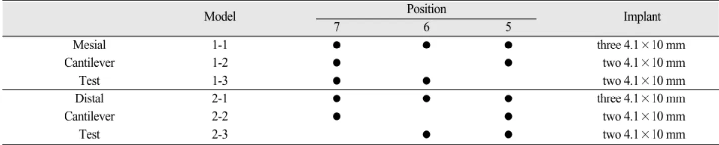
Experimental design is showed in Table Ⅰ. Models were divided for the test of different cantilever types. For mesial cantilever test, in model 1-1, three 4.1×10 mm implants
were placed at lower second premolar, first molar and second molar position. In model 1-2, two 4.1×10 mm implants were placed at lower second premolar position and second molar position. Model 1-2 had a fixed three-unit prosthesis with a central pontic (Fig. 2). In model 1-3, two 4.1×10 mm implants were placed at lower first molar and second molar position. Model 1-3 had a fixed three-unit prosthesis with a mesial pontic.: For distal cantilever test, in model 2-1, three 4.1×10 mm implants were placed at lower second premolar, first molar and second molar position. In model 2-2, two 4.1×10 mm implants were placed at lower second premolar position and second molar position. Model 2-2 had a fixed three-unit prosthesis with a central pontic. In model 2-3, two 4.1×10 mm implants were placed at lower second premolar and first molar position. Model 2-3 had a fixed three-unit prosthesis with a distal pontic. In model 1-1, 1-2 and 1-3, oblique 155 N load at 30 degrees with respect to the vertical axis in the sagittal plane was applied at the buccal cusp tip of second premolar.
In model 2-1, 2-2 and 2-3, oblique 206 N load at 30 degrees with respect to the vertical axis in the sagittal plane was applied at the buccal cusp tip of second molar.
In all models, the occlusal appearance of all prostheses were the same. Each crown or pontic of the prostheses resembled a premolar in shape. Therefore, all prostheses had the same mesio-distal dimension. The positions of implants were controlled to correspond to mesio-distal dimension of prostheses and to reflect Tarnow et al’s report.16,17
Fig. 1. 4.1×10 mm dental implant and 4 mm height abut- ment.
Fig. 2. Model 1-2.
The contact area between first premolar and distal prosthesis was established an ellipse which had the 2.5 mm major axis and the 2 mm minor axis.
The 3-D CAD models of the implants and superstructures were created using a modeling software (Pro/Engineer wildfire ver2.0; Parametric Technology Corp., Needham, MA, USA). Using HyperMesh (ver7.0; Altair Engineering, Inc., Troy, MI, USA), mesh generation was done, then, physical properties, loading condition and boundary condition were set. For example, the model 1-1 and 2-1 consisted of 224155 elements with 46660 nodes.
Implant-to-bone contact was assumed to be 100 percent.
Cement thickness was not considered. All materials were presumed linear elastic, homogeneous and isotropic. The physical properties were determined from the previous literatures and are showed in Table Ⅱ. The bone was fixed from its circumferential edge. Maximal occlusal forces were determined from the previous literature.18All applied loads were static. ABAQUS (ver6.4; ABAQUS Inc., Providence, RI, USA) analyzed the equation. Finally, HyperView (ver7.0; Altair Engineering, Inc., Troy, MI, USA) visualized the outcomes. Stress levels were calculated using von Mises stresses values.
RESULTS
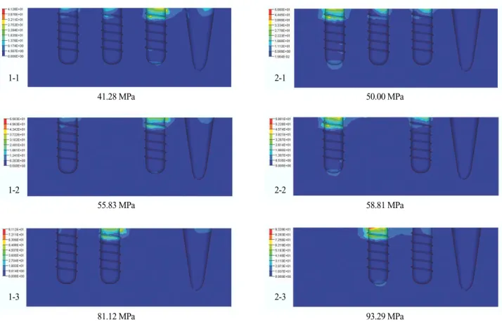
The more implants supported, the less stress was observed, regardless of applied occlusal load. Among the models without a cantilever, model 1-1 and 2-1 which had three implants, showed lower stress than model 1-2 and 2-2 which had two implants. Although model 2-1 was applied with 206 N, it showed lower stress than model 1-2 which was applied with 155 N.
In models that implant positions of models were same, the amount of applied occlusal load largely influenced the maximum von Mises stress. Model 1-1 and 1-2, which were loaded with 155 N, showed less stress than corresponding model 2-1 and 2-2 which were loaded with 206 N.
For the same number of implants, the existence of a cantilever induced the obvious increase of maximum stress.
Model 1-3 and 2-3 which had a cantilever, showed much higher stress than the others which had no cantilever. The ratio of maximum stress of model 1-3 to model 1-2 was 1.45. The ratio of maximum stress of model 2-3 to model 2- 2 was 1.59.
Fig. 3 represents stress distribution within the mandibular bone. In all models, the von Mises stresses were
Table I. Experimental design
Model Position
Implant
7 6 5
Mesial 1-1 ● ● ● three 4.1×10 mm
Cantilever 1-2 ● ● two 4.1×10 mm
Test 1-3 ● ● two 4.1×10 mm
Distal 2-1 ● ● ● three 4.1×10 mm
Cantilever 2-2 ● ● two 4.1×10 mm
Test 2-3 ● ● two 4.1×10 mm
Table II. Physical properties of materials
Material properties Young’s modulus (Gpa) Poisson’s ratio (μ)
Titanium (implant, abutment)19 110 0.35
Trabecular bone19 1.37 0.3
Cortical bone19 13.7 0.3
Type Ⅲ gold alloy20 96.6 0.35
Dentin21 18 0.31
Enamel20 48 0.33
Peridontal ligament22 0.069 0.45
concentrated at the cortical bone around the cervical region of the implants. Meanwhile, in model 1-1, 1-2 and 1-3, which were loaded on second premolar position, the first premolar participated in stress distribution. First premolars of model 2-1, 2-2 and 2-3 did not participated in stress distribution.
DISCUSSION
In the past two decades, finite element analysis has become an increasingly useful tool for the prediction of the effects of stress on the implant and its surrounding bone. A key factor for the success or failure of a dental implant is the manner in which stresses are transferred to the surrounding bone. Finite element analysis allows researchers to predict stress distribution in the contact area of the implants with cortical bone and around the apex of the implants in trabecular bone.21
The von Mises stress is the most commonly reported in FEA studies to summarize the overall state at a point.23
The occlusal morphology of the model may have an effect on the stress distribution. In clinical conditions, to minimize the leverage effect, the pontic should be kept as small as possible, more nearly representing a premolar than a molar.24,25In present study, all crowns and pontics of fixed dental prostheses took the shape of premolar.
In this study, two kinds of load were applied for the purpose of the test of different cantilever type. Because a different load could cause a different stress distribution, evidence-based selection of applied load was very important. There have been many researches for maximum occlusal force in case of implant rehabilitation.18, 26-32 For the case that implant-supported fixed prostheses occlude with opposing natural teeth or fixed prostheses, Mericske-Stern et al30,32measured the maximum occlusal force and oral tactile sensibility in partially edentulous patients with ITI
41.28 MPa 50.00 MPa
55.83 MPa 58.81 MPa
81.12 MPa 93.29 MPa
Fig. 3. Stresses distribution and maximum von Mises stress.
Observed maximum von Mises stresses were arranged in Fig. 3.
1-1
1-2
1-3
2-1
2-2
2-3
implants. However, they made no differentiation between first molar and second molar. Therefore, we did not consult their report. Kwon et al18 measured the maximal occlusal force of implant-supported fixed prostheses with a unilateral bite force recorder. They reported that maximal occlusal force on first premolar was 148±50 N, maximal occlusal force on second premolar was 155±78 N, maximal occlusal force on first molar was 186±74 N, and maximal occlusal force on second molar was 206±86 N. They made a differentiation between first molar and second molar. So, we consulted their report.
In the present study, the 30�oblique load was applied.
The rationale for use of oblique loading condition was based on the finding that the direction of the largest possible bite force does not always coincide with the direction perpendicular to the occlusal plane.33,34Much less stress occurs within vertical loads compared with an angled load on an implant.35That is, oblique load is more realistic bite directions and for a given force will cause the highest localized stress in cortical bone.36
Tarnow et al16showed about a vertical component to the bone loss that when the measurement from the contact point to the crest of bone was 5mm or less, the papilla was present almost 100%. About a lateral component to the bone loss, Tarnow et al17 suggested that a minimum of 3 mm of bone should be retained between multiple implants at the implant-abutment level. These vertical and lateral component were reflected on this finite element model design.
Load transfer from implants to surrounding bone depends on the type of loading, the bone-implant interface, the length and diameter of the implants, the shape and characteristics of the implant surface, the prosthesis type, and the quantity and quality of the surrounding bone.21 Among them, occlusal force and bone quality seldom can be altered by a dentist. Instead, a dentist can select implant type and prosthesis type with ease. That selection will be able to alter the biomechanics of implant-supported fixed cantilever prostheses more favorable. In this study, models with three implants always showed less stress than models with two implants. This results were derived from the more even distribution of applied occlusal load in models with three implants. The effect of stress distribution of more implants was enough to overcome the variation of applied
occlusal load which were set in this study.
Sullivan6agreed to use two implant fixtures supporting a three-tooth replacement prosthesis. English2and Misch4 recommended a mesial cantilever rather than a distal cantilever due to occlusal force. Buser et al3gave the guidelines for three missing occlusal units. The standard solution comprised the placement of two implants to support a three-unit fixed dental prosthesis with a central pontic. Besides, they insisted that a three-unit fixed partial denture with a mesial cantilever has proven to be a viable alternative, but a distal cantilever unit should only be used in exceptional situations. I·plik ioğlu et al., from a finite element study, concluded that with the use of two implants of 4.1mm diameter and 10mm length as terminal supports for three-unit fixed prostheses, the magnitude and the distribution of stresses in the cortical bone around the implant collar is within the normal physiological limits.37
Although several authors2-4 agreed to use a mesial cantilever, in the present study, model 1-3 with a mesial cantilever showed much higher maximum von Mises stress than the models without a cantilever. In fixed dental prosthesis with a cantilever, the resultant force imparted to the abutments during cantilever loading is often greater than the actual force applied to the cantilever. The fixtures adjacent to unilateral cantilever will be subjected to a compression force that is the sum of the applied occlusal force and the compensating tension force.24 On the other hand, Rangert et al5suggested that three unit prosthesis with mesial cantilever cause the double stress, compared with three unit prosthesis having a central pontic. In this study, for two models with a central pontic, model 2-2 showed higher stress than model 1-2. Model 1-3 had a mesial cantilever. However, the stress ratio of model 1-3 to model 2-2 was 1.39 rather than 2. In addition, even if Rangert et al5 did not mention fixed dental prosthesis having a distal cantilever, the stress ratio of model 2-3 having a distal cantilever to model 2-2 was 1.59. Both two models with a cantilever showed the favorable values of stress, being different from Rangert et al’s report.
In the models with a mesial cantilever, first premolar tooth supported a portion of stress. This may be resulted from the mesial rotation of the prostheses. In this study, the area of contact point between first premolar and distal prosthesis had been fixed. From this point, it is inferred that
if that contact area enlarges, the amount of stress which first premolar supports will increase, so the supporting bone of implant adjacent to mesial cantilever will be less stressed.
Further investigation will be needed in future study.
CONCLUSION
The conclusions derived from this study are limited to the assumptions made for the composition of the computer model and its boundary conditions. Within the limitations of this study, the followings were concluded.
1. The more implants supported, the less stress was induced, regardless of applied occlusal loads.
2. The existence of a cantilever induced the obvious increase of stress. The maximum von Mises stress in the bone of the implant-supported three-unit fixed dental prosthesis with a mesial cantilever was 1.38 times that with a central pontic. The maximum von Mises stress in the bone of the implant-supported three- unit fixed dental prosthesis with a distal cantilever was 1.59 times that with a central pontic.
3. A distal cantilever induced larger stress in the bone than a mesial cantilever.
4. A adjacent tooth which contacts implant-supported fixed prosthesis participated in the stress distribution.
REFERENCES
1. Becker CM, Kaiser DA. Implant-retained cantilever fixed prosthesis: Where and When. J Prosthet Dent 2000;84:432-5.
2. English CE. Biomechanical concerns with fixed partial dentures involving implants. Implant Dent 1993;2:221- 42.
3. Buser D, Belser UC, Lang NP. The original one-stage dental implant system and its clinical application.
Periodontology 2000 1998;17:106-18.
4. Misch CE. Dental Implant Prosthetics. St Louis:
Mosby; 2005. p. 184.
5. Rangert B, Krogh PHJ, Langer B, Roekel NV. Bending overload and implant fracture: a retrospective clinical analysis. Int J Oral Maxillofac Implants 1995;10;326- 34.
6. Sullivan D. Prosthetic considerations for the utilization of osseointegrated fixtures in the partially edentulous arch. Int J Oral Maxillofac Implants 1986;1:39-45.
7. Lindquist LW, Carlsson GE, Jemt T, A prospective 15-
year follow-up study of mandibular fixed prostheses supported by osseointegrated implants. Clinical results and marginal bone loss. Clin Oral Impl Res 1996;7:329-36.
8. Lambrecht JT, Filippi A, Kunzel AR, Schiel HJ. Long- term evaluation of submerged and nonsubmerged ITI solid-screw titanium implants: A 10-year life table analysis of 468 implants. Int J Oral Maxillofac Implants 2003;18:826-34.
9. Romeo E, Lops D, Margutti E, Ghisolfi M, Chiapasco M, Vogel G. Implant-supported fixed cantilever pros- theses in partially edentulous arches. a seven-year prospective study. Clin Oral Impl Res 2003;14:303-11.
10. Becker CM. Cantilever fixed prostheses utilizing dental implants: a 10-year retrospective analysis.
Quintessence Int 2004;35:437-41.
11. White SN, Caputo AA, Anderkvist T. Effect of can- tilever length on stress transfer by implant-supported prostheses. J Prosthet Dent 1994;71:493-9.
12. Tashkandi EA, Lang BR, Edge MJ. Analysis of strain at selected bone sites of a cantilevered implant-support- ed prosthesis. J Prosthet Dent 1996;76:158-64.
13. Wang S, Hobkirk JA. Load distribution on implants with a cantilevered superstructure : an in vitro pilot study. Implant Dent 1996;5:36-42.
14. Stegaroiu R, Sato T, Kusakari H, Miyakawa O.
Influence of restoration type on stress distribution in bone around implants: a three-dimensional finite ele- ment analysis. Int J Oral Maxillofac Implants 1998;13:82-90.
15. Yokoyama S, Wakabayashi N, Shiota M, Ohyama T.
The influence of implant location and length on stress distribution for three-unit implant-supported posterior cantilever fixed partial dentures. J Prosthet Dent 2004;91:234-40.
16. Tarnow DP, Magner AW, Fletcher P. The effect of the distance from the contact point to the crest of bone on the presence or absence of the interproximal dental papilla. J Periodontol 1992;63:995-6.
17. Tarnow SC, Cho SC, Wallace SS. The effect of inter- implant distance on the height of inter-implant bone crest. J Periodontol 2000;71:546-9.
18. Kwon YS, Hwang SH, Han DH. Comparison of maxi- mum occlusal forces on osseointegrated implant sup- ported fixed prostheses and natural teeth. J Korean Acad Prosthodont 2005;43:498-510.
19. Eskitascioglu G, Usumez A, Sevimay M, Soykan E, Unsal E. The influence of occlusal loading location on stresses transferred to implant-supported prostheses and supporting bone: A three-dimensional finite element study. J Prosthet Dent 2004;91:144-50.
20. Ak a K, I·plik ioğlu H. Finite element stress analysis of the effect of short implant usage in place of cantilever
extensions in mandibular posterior edentulism. J Oral Rehabil 2002;29:350-6.
21. Geng JP, Tan KBC, Liu GR. Application of finite ele- ment analysis in implant dentistry: A review of the lit- erature. J Prosthet Dent 2001;85:585-98.
22. Eranslan O, Sevimay A, Usumez A, Eskitascioglu G.
Effects of cantilever design and material on stress dis- tribution in fixed partial dentures-a finite element analysis. J Oral Rehabil 2005;32:273-8.
23. Sevimay M, Turhan F, Kili arslan MA, Eskitascioglu G. Three-dimensional finite element analysis of the ef- fect of different bone quality on stress distribution in an implant-supported crown. J Prosthet Dent 2005;
93:227-34.
24. Rangert B, Jemt T, Jo¨rne´us L. Forces and moments on Bra�nemark implants. Int J Oral Maxillofac Implants 1989;4:241-7.
25. Kim Y, Oh TJ. Misch CE, Wang HL. Occlusal consid- erations in implant therapy: clinical guidelines with biomechanical rationale. Clin Oral Impl Res 2005;
16:26-35.
26. Haraldson T, Carlsson GE. Bite force and oral function in patients with osseointegrated oral implants. Scand J Dent Res 1977;85:200-8.
27. Haraldson T, Zarb G. A 10-year follow-up study of the masticatory system after treatment with osseointegrated implant bridges. Scand J Dent Res 1988;96:243-52.
28. Jemt T, Karlsson S. Occlusal force and mandibular movements in patients with removable overdentures and fixed prostheses supported by implants in the max- illa. Int J Oral Maxillofac Implants 1993;8:301-8.
29. Mericske-stern R, Hofmann J, Wedig A, Geering AH.
In vivo measurements of maximal occlusal force and minimal pressure threshold on overdentures supported
by implants or natural roots: a comparative study, part 1. Int J Oral Maxillofac Implants 1993;8:641-9.
30. Mericske-stern R, Zarb GA. In vivo measurements of some functional aspects with mandibular fixed prosthe- ses supported by implants. Clin Oral Impl Res 1996;7:
153-61.
31. Fontijn-Tekamp FA, Slagter AP, van’t Hof MA, Greetman ME, Kalk W. Bite forces with mandibular implant-retained overdentures. J Dent Res 1998;77:
1832-9.
32. Mericske-stern R, Assal P, Mericske E, B?rgin W.
Occlusal force and oral tactile sensibility measured in partially edentulous patients with ITI implants. Int J Oral Maxillofac Implants 1995;10:345-54.
33. Koolstra JH, van Eijden TMGJ, Weijs WA, Naeije M.
A three-dimensional mathematical model of the human masticatory system predicting maximum possible bite forces. J Biomechanics 1988;21:563-76.
34. van Eijden TMGJ. Three-dimensional analyses of hu- man bite-force magnitude and moment. Archs oral Biol 1991;36:535-9.
35. Misch CE. Dental Implant Prosthetics. St Louis:
Mosby; 2005. p. 100-101.
36. Holmgren EP, Seckinger RJ, Kilgren LM, Mante F.
Evaluation parameters of osseointegrated dental im- plants using finite element analysis-A two-dimensional comparative study examining the effects of implant di- ameter, implant shape, and load direction. J Oral Implantol 1998;24:80-8.
37. I·plik ioğlu H, Ak a K. Comparative evaluation of the effect of diameter, length, and number of implants sup- porting three-unit fixed partial prostheses on stress dis- tribution in the bone. J Dent 2002;30:41-6.
EFFECT OF NUMBER OF IMPLANTS AND CANTILEVER DESIGN ON STRESS DISTRIBUTION IN THREE-UNIT FIXED PARTIAL DENTURES:
A THREE-DIMENSIONAL FINITE ELEMENT ANALYSIS
Ji-Hyun Park1, DDS, MSD, Sung-Hun Kim2, DDS, PhD, Jung-Suk Han3, DDS, MSD, PhD, Jai-Bong Lee3, DDS, MSD, PhD, Jae-Ho Yang3*, DDS, MSD, PhD
1Graduate student, Department of Prosthodontics and Dental Research Institute, Seoul National University
2Associate professor, Department of Prosthodontics, School of Dentistry, Seoul National University
3Professor, Department of Prosthodontics, School of Dentistry, Seoul National University
STATEMENT OF PROBLEM: Implant-supported fixed cantilever prostheses are influenced by various biomechanical factors. The infor- mation that shows the effect of implant number and position of cantilever on stress in the supporting bone is limited. PURPOSE: The pur- pose of this study was to investigate the effect of implant number variation and the effect of 2 different cantilever types on stress distribu- tion in the supporting bone, using 3-dimensional finite element analysis. MATERIAL AND METHODS: A 3-D FE model of a mandibu- lar section of bone with a missing second premolar, first molar, and second molar was developed. 4.1×10 mm screw-type dental implant was selected. 4.0 mm height solid abutments were fixed over all implant fixtures. Type III gold alloy was selected for implant-supported fixed prostheses. For mesial cantilever test, model 1-1 which has three 4.1×10 mm implants and fixed prosthesis with no pontic, model 1-2 which has two 4.1×10 mm implants and fixed prosthesis with a central pontic and model 1-3 which has two 4.1×10 mm implants and fixed prosthesis with mesial cantilever were simulated. And then, 155N oblique force was applied to the buccal cusp of second premolar.
For distal cantilever test, model 2-1 which has three 4.1×10 mm implants and fixed prosthesis with no pontic, model 2-2 which has two 4.1×10 mm implants and fixed prosthesis with a central pontic and model 2-3 which has two 4.1×10 mm implants and fixed prosthesis with distal cantilever were simulated. And then, 206N oblique force was applied to the buccal cusp of second premolar. The implant and su- perstructure were simulated in finite element software(Pro/Engineer wildfire 2.0). The stress values were observed with the maximum von Mises stresses. RESULTS: Among the models without a cantilever, model 1-1 and 2-1 which had three implants, showed lower stress than model 1-2 and 2-2 which had two implants. Although model 2-1 was applied with 206N , it showed lower stress than model 1-2 which was applied with 155N. In models that implant positions of models were same, the amount of applied occlusal load largely influenced the maxi- mum von Mises stress. Model 1-1, 1-2 and 1-3, which were loaded with 155N, showed less stress than corresponding model 2-1, 2-2 and 2- 3 which were loaded with 206N. For the same number of implants, the existence of a cantilever induced the obvious increase of maximum stress. Model 1-3 and 2-3 which had a cantilever, showed much higher stress than the others which had no cantilever. In all models, the von Mises stresses were concentrated at the cortical bone around the cervical region of the implants. Meanwhile, in model 1-1, 1-2 and 1-3, which were loaded on second premolar position, the first premolar participated in stress distribution. First premolars of model 2-1, 2-2 and 2-3 did not participate in stress distribution. CONCLUSION: 1. The more implants supported, the less stress was induced, regardless of applied occlusal loads. 2. The maximum von Mises stress in the bone of the implant-supported three unit fixed dental prosthesis with a mesial cantilever was 1.38 times that with a central pontic. The maximum von Mises stress in the bone of the implant-supported three-unit fixed dental prosthesis with a distal cantilever was 1.59 times that with a central pontic. 3. A distal cantilever induced larger stress in the bone than a mesial cantilever. 4. A adjacent tooth which contacts implant-supported fixed prosthesis participated in the stress distribution.
KEY WORDS: Implant, Mesial cantilever, Distal cantilever, von Mises stress
Corresponding Author: Jae-Ho Yang
Department of Prosthodontics, College of Dentistry, Seoul National University
28 Yeongun-Dong, Jongno-Gu, Seoul, 110-749, Korea +82 2 2072 3393: e-mail, [email protected] Received May 27, 2008 Last Revison June 10, 2008 Accepted June 20, 2008.