• 검색 결과가 없습니다.

Design optimization of the outlet holes for bone crystal growing with bioactive materials in dental implants: Part II. number and shapes

N/A
N/A
Protected

Academic year: 2021

Share "Design optimization of the outlet holes for bone crystal growing with bioactive materials in dental implants: Part II. number and shapes"

Copied!
5
0
0

로드 중.... (전체 텍스트 보기)

전체 글

(1)

http://dx.doi.org/10.6111/JKCGCT.2013.23.2.76

Design optimization of the outlet holes for bone crystal growing with bio- active materials in dental implants: Part II. number and shapes

Kangsoo Lee, Geug Tae Kim* and Yong Keun Lee**

,†

Department of Advanced Materials Engineering, Kyonggi University, Suwon 443-760, Korea

*Department of Nano-bio Chemical Engineering, Hannam University, Daejeon 305-811, Korea

**Graduate School of NID Fusion Technology, Seoul National University of Science and Technology, Seoul 139-743, Korea (Received January 21, 2013)

(Revised March 11, 2013) (Accepted March 22, 2013)

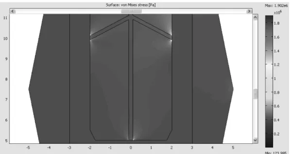
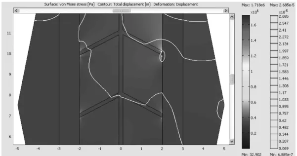
Abstract For further improvement of osseo-integration of bone crystal with a dental implant, a design optimization study is carried out for various holes inside its body to deliver bioactive materials and the effect of bioactive material injection on the bone crystal growing. When bioactive material is absorbed, the bone crystal can grow into holes, which would increase the strength of implant bonding as well as a surface integration. The stress concentrations near the uppermost outlet holes were reduced with increasing the number of outlet holes. A design improvement in the uppermost outlet was shown to be effective in reducing the stress concentration. For design parameters under consideration in this study, total area of outlet of 6.38 mm

2

and maximum stress of 1.114 MPa, which corresponds to type 6-C. It is due to the minimization of maximum stress and total area of outlet. The design of the outlet facing down was more effective in reducing the maximum stress value compared with a horizontal symmetry.

Key words Bone crystal, Dental implant, Finite element, Bioactive material, Outlet holes

1. Introduction

A dental implant is an artificial tooth root used in dentistry to support restorations that resemble a tooth or group of teeth [1]. Dental implants can be used to sup- port a number of dental prostheses, including crowns, implant-supported bridges or dentures [2-4]. It is neces- sary to lengthen the lifetime of implants and to acceler- ate the formation process of the bone materials. Until now, there is little research on the improvement of the initial anchorage of the implant as well as the preserva- tion of the strength of the bone materials to implant interface. Moreover, the previous results are not satisfac- tory and further technical studies are required. In general, the bone crystal obtained from carbonated hydroxyapa- tite with lower crystallinity make globular and plate structures distributed among the collagen fibrils of bone, and then relatively large structure [5].

The encapsulated biological agents are loaded into hollow and porous implants, and promote the formation of bone materials or tooth structures. A combination of porosity and controlled release techniques produces a

novel dental and/or orthopedic implant system which accelerates bone materials and osseo-integration (inte- gration of titanium into host bone materials or teeth).

The technology of controlled release delivers scheduled doses of formation factors and/or other chemical and/or pharmacological substances in a pre-defined temporal and spatial manner to promote bone material and/or osseo- integration. The physical signs of the pores and hollow cylinder can be altered to optimize bone materials and/

or osseo-integration.

A majority of dental implants currently available are in shape like small screws, with either tapered or paral- lel sides. They can be placed simultaneously as a tooth is removed by engaging with the bone materials of the socket wall and sometimes also with the bone materials beyond the tip of the socket. Recent research shows that implants placed straight into an extraction socket have comparable success rates to those placed into healed bone materials [6, 9]. The radiographic results of imme- diate restorations of dental implants placed in fresh extraction sockets, for the temporary crowns placed at the same time, have been shown to be comparable to those obtained with delayed loading, for the crowns placed weeks or months later, in carefully selected cases [7].

A typical implant consists of a titanium screw resem-

Corresponding author

Tel: +82-2-970-6594

H.P.: +82-10-6714-3380

E-mail: yklee@snut.ac.kr

(2)

bling a tooth root with a roughened or smooth surface.

A majority of dental implants are made out of commer- cially pure titanium, which is available in 4 grades depending upon the content amount of carbon and iron.

More recently the use of titanium of grade 5 has increased. Titanium 6AL-4V, is known to offer osseo- integration levels similar to commercially pure titanium.

The Ti-6Al-4V alloy offers better tensile strength and fracture resistance. Today most chosen implants are made out of commercially pure titanium (grades 1 to 4) but some implant systems are sometimes fabricated out of the Ti-6Al-4V alloy. In general, implant surfaces may be modified by plasma spraying, anodizing [8], etching or sandblasting to increase the surface area and the integra- tion potential of the implant. An implant, be it dental, orthopedic or other, is usually a biologically compatible material, like titanium, which is surgically inserted within the body to replace defective structures such as bone materials or teeth. Although these implants are becoming more commonplace, problems still remain in the area of osseo-integration, both immediate and long-term. Most of implant procedures focus on mechanical repair not considering the regeneration of bone materials. The replacement of bone materials such as hip joints that initially osseo-integrate properly deteriorate years later because of osteolysis at the bone materials to implant interface.

In this study, we investigate the changes of the maxi- mum stress at the outlet holes with increasing the size and the number of outlet holes or by altering either the shape or location of outlet holes, and discuss over corre- lations between the design elements and the mechanical properties.

2. Research Procedure

A two dimensional simulation was carried out by the finite element method [10], which covered parameters such as the structural properties of an implant, the stress distribution, and properties of holes such as location, shape, and the number. For the numerical investigation,

the diameters of 0.2 to 1 mm and 0.2 to 2 mm were chosen for an inlet and an outlet of a hole, respectively.

Locations of an inlet, outlets, and connecting holes were varied to optimally re-distribute and reduce stress on an implant. The number of outlets was varied from 2 up to 5. We used COMSOL, a multiphysics FEM tool, to make two dimensional model of an implant and mandible and analyzed stress distribution before and after bioactive material was injected through holes. Since COMSOL can simulate three dimensional models, this two dimen- sional model will serve as a starting point for the com- prehensive analyses described. As the further study, the three dimensional structural design is needed based on the two dimensional analysis, and also considers a situa- tion when bone materials fill those holes from outlets.

The three dimensional simulation will include specific requirements for implant administration and this will improve three dimensional models in applications for diverse patients. The formation process of bone materi- als with biological factors like mechanical properties of bone materials around and inside of an implant system is studied with the resulting transient simulation.

3. Results and Discussion

The number of outlet holes is a design element related to the cross-sectional area of the outlet holes as well as the shape of the outlet holes. One of widely used meth- ods to reduce the maximum stress value is to increase the cross-sectional areas of the outlet holes, and espe- cially the uppermost outlet design improvement is more effective in reducing the stress concentration. Triangu- lar elements were used to make a mesh, and implanted and outlet areas had dense elements for more accurate analysis. Models consisted of 9,778 elements for an implant with one inlet and four outlets. Titanium beta- 215 was used to model an implant fixture (Table 1). We assumed that bone crystals grow and fill the holes after bioactive material is applied if it was absorbed and leaved holes. In this case the bone crystals filling the holes are assumed to be compound of both cortical and

Table 1

Max. stress changes with number of groove variations Type

(# of Groove)

Size of inlet (mm)

Size of 2 top outlet (mm)

Size of 2 middle outlet (mm)

Size of 1 bottom outlet (mm)

Total area of outlets (mm

2

)

Change of outlet area (%)

Max stress (MPa)

Change of max stress (%)

4-A 0.2 0.2 0 0.2 0.0942 0 1.902 0

5-B 0.2 0.2 0.2 0 0.1256 33.3 1.757 7.6

6-D 0.2 0.2 0.2 0.2 0.1570 25 1.718 2.2

(3)

cancellous bone crystals. Since this situation was not reported yet, the mechanical property of this compound was determined by the surface ratio of cortical and can- cellous bone crystals. Loads applied in the analysis was set to be 400 N/m downward and 75 N/m right, which was a bit greater than those usually applied in a real patient. The load was set to be evenly distributed in the upper part of the implants.

Boundary conditions are like this.

On the top of Implant Loading F

y

= −400 N/m F

x

= 75 N/m

Fig. 2. Type 4-A, Stress Contour Zooming at 3 Outlets (Max. stress = 1.902 MPa, Min. stress = 124 Pa).

Fig. 1. Variation of number of grooves: 3 outlets (0.0942 mm

2

), 4 outlets (0.1256 mm

2

), 5 outlets (0.1570 mm

2

).

Fig. 3. Type 5-B, Stress Contour Zooming at 4 Outlets (Max. stress = 1.757 MPa, Min. stress = 110 Pa).

(4)

At the boundary of implant contact

cancellous bone crystal D

x

= 4e

−6

m

At 4 outlet holes Fixed

Fig. 1 shows various grooves with variations: 3 outlets (0.0942 mm

2

), 4 outlets (0.1256 mm

2

), 5 outlets (0.1570 mm

2

). In Fig. 1, the diameters of injection and outlet holes were fixed, and the number of outlet holes was varied from 3 to 5 to study the effects of the number of the outlet holes on the design optimization. The bound- ary conditions including the loadings and the density of the mesh of 9,000~10,000 are kept at the same values.

With increasing the number of outlet, the corresponding area is increased with an increase of 0.0314 mm

2

. As shown in Figs. 2~4, from the viewpoint of the stress contours, the maximum stress value was reduced as the number of the outlet holes was increased (1.902 MPa >

1.757 MPa > 1.718 MPa). However, the reducing rate of the maximum stress value with the increasing number of the outlet holes showed a decreasing trend (from 4-A to 5-B, 7.6%, and from 5-B to 6-D, 2.2%), as shown in Table 1. The result, that the stress concentrations near the uppermost outlet holes were also reduced with an increasing number of outlet holes, is worthy of notice.

These results were summarized in Table 1.

In Fig. 5 and Table 2, the various shapes of outlet holes were analyzed and summarized to study the effects of the shape of the outlet holes on the design optimiza- tion. In the case of the same cross-sectional area of the outlet holes, the maximum stress value was increased from 1.348 MPa (Type 6-B) to 1.403 MPa (Type 6-E).

This proved that the shapes of outlet holes could be the

one of the design elements. The design of the outlet fac- ing down was more effective to reduce the maximum stress value than that of the horizontal symmetry. The Type 6-G with the largest cross-sectional area and Type 6-C showed the similar maximum stress values. Type 6- C (cross-sectional area = 6.38 mm

2

, maximum stress = 1.114 MPa) and Type 6-F (larger cross-sectional area = 8.64 mm

2

, larger maximum stress = 1.991 MPa) con- firmed that the shapes of outlet holes could be the one of the design elements. Therefore, the studies on over- Fig. 4. Type 6-D, Stress Contour Zooming at 5 Outlets (Max. stress = 1.718 MPa, Min. stress = 32 Pa).

Fig. 5. Different types of groove designs.

(5)

all shape optimization of the shape, location, number, and so on, of the outlet holes, are carried out.

4. Conclusions

The stress concentrations near the uppermost outlet holes were also reduced with an increasing number of outlet holes. The conclusion, that the uppermost outlet design improvement was most effective to reduce the stress concentration and improve the growth rate of bone crystal, could be drawn. This conclusion is not out of sense considering the loads in the boundary condi- tion. After the design optimizations, Type 6-C had pro- vided the best results in this study. Type 6-C design had the 3 cone-shaped outlet holes (0.4 mm inlet diameter and 1.0 mm outlet diameter) and 2 larger cross-sec- tional area of the upper outlet holes (0.4 mm inlet diam- eter and 1.6 mm outlet diameter) facing down, and showed the lowest value (1.114 MPa) of the maximum stress and the stress concentration was also decreased dramatically farther away from the uppermost outlet holes. The various shapes of outlet holes were ana- lyzed, and the design of the outlet facing down was more effective to reduce the maximum stress value than that of the horizontal symmetry. The Type 6-G with the largest cross-sectional area and Type 6-C showed the similar maximum stress values. Type 6-C (cross-sec- tional area = 6.38 mm

2

, maximum stress = 1.114 MPa) and Type 6-F (larger cross-sectional area = 8.64 mm

2

, larger maximum stress = 1.991 MPa) confirmed that the shapes of outlet holes could be the one of the design elements. Therefore, the overall shape optimization stud- ies on the shape, location, number, and so on, of the outlet holes, should be carried out further. These results of this study will be used to obtain the transient solutions considering shape optimizations and bioactive factors.

Acknowledgement

This study was financially supported by Seoul National University of Science & Technology.

References

[ 1 ] P.I. Bra

o

nemark, U. Breine, R. Adell, B.O. Hansson, J.

Lindstrom and A. Ohlsson, “Intra-osseous anchorage of dental prostheses. I. Experimental studies”, Scand. J.

Plast. Reconstr. Surg. Hand Surg. 3 (1969) 81.

[ 2 ] E.J. Richter, “Basic biomechanics of dental implants in prosthetic dentistry”, J. Prosthet. Dent. 61 (1989) 602.

[ 3 ] P.I. Bra

o

nemark, “Osseointegration and its experimental background”, J. Prosthet. Dent. 50 (1983) 399.

[ 4 ] I.P. Van Rossen, L.H. Braak, C. de Putter and K. de Groot, “Stress-absorbing elements in dental implants”, J.

Prosthet. Dent. 64 (1990) 198.

[ 5 ] S. Bertazzo and C.A. Bertran, “Morphological and dimensional characteristics of bone mineral crystals”, Bioceramics 18 (2006) 7.

[ 6 ] M. Quirynen, N. Van Assche, D. Botticelli and T. Ber- glundh, “How does the timing of implant placement to extraction affect outcome?” Int. J. Oral Maxillofac.

Implants 22 Suppl. (2007) 203.

[ 7 ] R. Crespi, P. Capparé, E. Gherlone and G.E. Romanos,

“Immediate versus delayed loading of dental implants placed in fresh extraction sockets in the maxillary esthetic zone: a clinical comparative study”, Int. J. Oral Maxillofac. Implants 23 (2008) 753.

[ 8 ] R. Palmer, “Ti-unite dental implant surface may be superior to machined surface in replacement of failed implants”, J. Evid. Base. Dent. Pract. 7 (2007) 8.

[ 9 ] J.K. Lee, Y.H. Ko and N.H. Lee, “Biocompatibility of porous hydroxyapatite ceramics prepared from bovine bones”, J. Kor. Cryst. Growth Cryst. Tech. 22 (2012) 139.

[10] S.J. Lim, H.Y. Shin, J.H. Kim and J.I. Lim, “Finite ele- ment analysis for czochralski growth process of sap- phire single crystal”, J. Kor. Cryst. Growth Cryst. Tech.

21 (2011) 193.

Table 2

Design variations of inlet and outlet of groove with Max. stress Type

(# of Groove)

Size of inlet (mm)

Size of 2 top outlet (mm)

Size of 2 middle outlet (mm)

Size of 1 bottom outlet (mm)

Total area of outlets (mm

2

)

Max stress (MPa)

6-B 0.4 1.0 1.0 1.0 3.93 1.348

6-C 0.4 1.6 1.0 1.0 6.38 1.114

6-E 0.4 1.0 1.0 1.0 3.93 1.403

6-F 0.4 2.0 1.0 1.0 8.64 1.991

6-G 0.4 1.6 1.6 1.0 8.82 1.113

수치

Fig. 3. Type 5-B, Stress Contour Zooming at 4 Outlets (Max. stress = 1.757 MPa, Min. stress = 110 Pa).
Fig. 1 shows various grooves with variations: 3 outlets (0.0942 mm 2 ), 4 outlets (0.1256 mm 2 ), 5 outlets (0.1570 mm 2 )

참조

관련 문서

: Bone response to unloaded titanium implants with a sandblasted and acid-etched surface : A histomorphometric study in the canine mandible.. : Early

These optimum design requirements include: i) a minimum number of tube turns for a PHP operable in top heat mode, ii) the use of R-123 as working fluid with 50 % charging

Calcium metaphosphate(CMP) Bioactive glasses.. 1 Bioactive spectra for various bioceramic implants.. Solubility of calcium phosphate

This study is an analysis of distribution of patient who installed Endopore Ⓡ at maxilla in Chosun University Dental hospital and types of implant for about 4

success rates of dental implants placed at the time of or after alveolar ridge augmentation with an autogenous mandibular bone graft and titanium mesh: a 3-to

Histologic evaluation of early human bone response to different implant surfaces2. Histologic evaluation of human bone integration on machined and

Consequently, the present study was designed to investigate the effect of adding 60 mg of raloxifene hydrochloride daily to women treated with GnRH-a for severe endometriosis

선박기본설계개론, 2006.3 Computer Aided Ship Design 2008 Computer Aided Ship Design 2008 –– PART III: Optimization Methods , 2006.3 PART III: