• 검색 결과가 없습니다.

Three dimensional finite element analysis of the stress on supporting bone by the abutment materials of dental implant

N/A
N/A
Protected

Academic year: 2021

Share "Three dimensional finite element analysis of the stress on supporting bone by the abutment materials of dental implant"

Copied!
7
0
0

로드 중.... (전체 텍스트 보기)

전체 글

(1)

http://doi.org/10.14347/kadt.2019.40.1.41

치과용 임플란트 지대주 재료에 따른 지지골 응력의 3차원 유한요소 분석

이명곤, 김갑진

부산가톨릭대학교 보건과학대학 치기공학과

Three dimensional finite element analysis of the stress on supporting bone by the abutment materials of dental implant

Myung-Kon Lee, Kap-Jin Kim

Department of Dental Laboratory Science, Catholic University of Pusan

[Abstract]

Purpose: The purpose of this study was to analyze the biomechanical properties of the dental implants on the supporting bone using three-dimensional finite element method when three different abutment materials were applied to the implant system.

Methods: Three different dental implant models were fabricated by applying Ti, PEEK, and CRE-PEEK (60% carbon- reinforced PEEK) to abutment material. The abutment and connecting screw from the fixture was applied with a tightening torque of 20 Ncm. And then, total loads of 150 N were applied in an 30°oblique direction (to the vertical). The structural stability of dental implants on the supporting bone was analyzed using Von Mises stress and principal stress values.

Results: The maximum tensile stress of the cortical bone was highest at 12.6 MPa in the PEEK abutment (Model-B).

Ti abutment (Model-A) and CRE-PEEK abutment (Model-C) showed similar stress distributions (10.6 and 10.3 MPa, respectively). And the maximum compressive principal stress was similar in all models. The Von Mises stress value delivered to the bone around the implant was highest at 16.5 MPa in Model-B. On the other hand, Model-A and C showed similar stress distributions (14.0 and 13.8 MPa, respectively). In addition, the maximum equivalent stress applied to the abutment was highest at 629.8 MPa in Model-A. The stress distribution in Model-C was 573.9 MPa. Whereas, Model-B showed the lowest value at 165.6 MPa.

Conclusion : The dental implant supporting bone system using PEEK material seems to have the possibility of supporting bone fracture. It was found that the CRE-PEEK abutment can reduce the elastic deformation and reduce the stress value of the interfacial bone.

Key words: Dental implant, Abutment, Supporting bone, Stress, Finite element analysis

Corresponding author

Name 이 명 곤 Tel. 051-510-0599 E-mail [email protected]

Address 부산시 금정구 오륜대로 57 부산가톨릭대학교 보건과학대학 치기공학과

* 본 연구는 2017년도 부산가톨릭대학교 교내연구비에 의하여 연구되었음

(2)

I. 서 론

치과용 임플란트는 골 유착 개념을 바탕으로 도입되 어 결손치 환자에게 인공치근 역할을 수행하는 효과적 인 치료법으로 적용되고 있으며, 높은 임상적 성공률을 바탕으로 수요가 지속적으로 증가하고 있다(Zhang et al, 2016). 임상적 치료 결과 보고에 따르면, 올바른 설 계와 제조를 바탕으로 제작된 치과용 임플란트 보철물 은 5년 동안 유지율이 95%를 초과하는 높은 성공률을 보인다고 하였다(Zhang et al, 2016. Calandriello &

Tomatis, 2011).

치과용 임플란트의 성공은 주변 지지골에 응력이 전달 되는 방식에 달려있다. 임플란트에서 주변 지지골의 하 중 전달은 교합하중 유형, 지지골과 임플란트 경계면 특 성, 임플란트 고정체 길이와 직경, 임플란트 고정체 표 면 특성, 보철물 유형, 지지골의 양과 질에 따라 다르게 나타날 수 있다(Herekar et al, 2014). 임플란트와 지 지골 경계면에서의 임플란트 설계와 하중 분포 간의 관 계는 계속 중요한 문제로 남아 있으며, 생체역학적인 관 점에서, 하중으로 인한 최대 지지골 응력을 최소화하 는 형상 및 소재로 임플란트를 설계하는 것은 중요하다 (Culhaoglu et al, 2013). 따라서 최근 임플란트 제조업 체는 임플란트 주위의 응력을 줄일 수 있는 임플란트 설 계 및 재료를 개발하는 것에 초점을 두고 있다.

치과용 임플란트 관련 연구 주제는 임플란트의 형상, 표면처리 그리고 보철물 구성품의 심미적 요소 등으로 매우 광범위하게 논의되고 있으며, 최근 기존의 티타늄 (titanium) 소재의 임플란트를 대체하기 위한 중합체 사용이 도입 연구되고 있다(Sarot et al, 2010).

PEEK(poly-ether-ether-ketone)는 치아 색상을 가지는 중합체이며 정형외과 분야에서 수년간 사용되 고 있는 소재이다. PEEK 소재의 주요 장점은 인체 뼈 와 유사한 탄성 계수(3 ~ 4 GPa)를 가지고 있는 것이다 (Skinner, 1988). 또한 다른 소재와 혼합하여 쉽게 물성 치를 개선할 수 있다. 예를 들면, 탄소 섬유를 혼합했을 때 18 GPa까지 탄성 계수를 증가시킬 수 있다(Najeeb et al, 2016).

Ti 및 Ti 합금은 뼈보다 상당히 높은 탄성계수를 가지

et al, 2012). 반면에 탄소 강화(carbon-reinforced) PEEK의 탄성계수는 피질골과 상아질의 계수와 비슷하 여 임플란트 재료로 사용된 Ti에 비해 응력 차폐가 적다 (Staines, 1981). 또한 PEEK의 인장 특성은 뼈, 법랑질 그리고 상아질 인장 특성과 유사하기 때문에 안정적인 수복 재료로 적용될 수 있다(Rees, 1993).

PEEK 소재는 티타늄 소재의 고유한 골전도성 특성 (osteoconductive property)에 대해서 제한적인 특성을 가지고 있다(Rabiei & Sandukas, 2013). 골전도성 특 성을 개선하기 위해 PEEK 표면을 코팅하거나 생체활성 입자를 분산시키는 다양한 연구가 진행되고 있지만(Lai et al, 2007; Barkarmo et al, 2013) PEEK를 고정체 로 적용하는 것은 임상적으로 계속 연구가 필요한 문제 로 남아있다.

유용성이 높은 PEEK 소재를 임플란트 시스템의 지대 주로 활용했을 때, 기존 Ti 소재를 이용한 지대주보다 가공성 및 경제성이 우수할 것으로 예상된다. 따라서 본 연구에서는 PEEK 소재를 임플란트 시스템의 지대주로 적용했을 때 지지골에 미치는 생체역학적 특성을 분석 하여 임플란트 새로운 소재에 대한 자료를 제공하고자 한다.

Ⅱ. 연구 방법

1. 3차원 실험 모델 설계

3차원 점 데이터 추출을 통해 실험 CAD 모델은 리버 스 엔지니어링 기술(reverse engineering technique) 을 사용하여 제작하였다. 본 연구에서 사용 모델은 국 내 D사의 임플란트 시스템의 고정체(4.5 mm × 8.5 mm), 지대주나사(Ø 1.8 mm × 8.5 mm) 및 스캔 데 이터를 활용한 맞춤형 지대주이다.

전제적인 형상은 대구치 영역에서 인체 하악골의 횡 단면 이미지를 기반으로 하악골 블록 모델을 구성하 였다. 높이 29.5 mm, 너비 14 mm, 그리고 두께 1.4

~ 3.7 mm 피질골로 둘러싸인 형상으로 해면골과 분

(3)

리하여 설계하였다(Fig. 1). 이러한 모델을 통해 NX 10(Siemens PLM Software, Germany) 프로그램을 이 용하여 정밀하게 시뮬레이션 하였다.

또한 ABAQUS Workbench 6.12에서 3차원 CAD 지 오메트리 모델을 가져와 유한요소를 생성하고 수치 시 뮬레이션을 수행했다. ABAQUS 요소 라이브러리는 쉽 게 사용 할 수 있는 C3D10 유형 요소를 사용하여 모든 요소를 10 node 4 면체 요소(평균 크기: 0.5 mm)로 설 정 하였다.

2. 하중, 나사 조임토크 및 구속조건

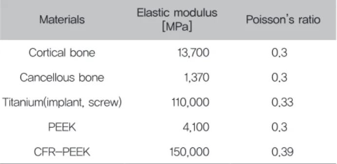
맞춤형 지대주, 임플란트, 지대주나사, 피질골 및 해면 골은 등방성, 균질 선형 탄성재료로 가정하였으며, 골과 임플란트 구성요소의 재료 특성(Table 2)은 신뢰 할 수 있는 자료와 게시된 데이터에서 수집하였다(Verplancke et al, 2011. Schwitalla et al, 2015). 또한 임플란트와 주위 지지골 사이의 결합은 완전한 접착으로 가정되었으 며, 지지골 하부 표면의 X, Y, 그리고 Z 방향으로 구속하 였다.

Figure 1. Schematic diagram of single implant dimensional data

지대주 나사 조임토크는 식 (1) 방정식을 사용하여 계 산되었다. 여기서 T는 나사 조임토크, D는 스크류 직 경, F는 나사의 전하중이며, K는 토크 계수 (0.2)를 의 미한다. 이 수식은 표준 조건에서 사용되는 표준 나사 의 조임토크를 나타낸다. 따라서 본 연구에 적용된 20

N·cm에 해당하는 전하중은 556 N이다.

Table 1. Characteristics of different tested models

Model Abutment of materials

Model-A Titanium

Model-B PEEK

Model-C CFR-PEEK*

* CRE-PEEK (60% carbon-reinforced PEEK)

Table 2. Mechanical properties of the materials

Materials Elastic modulus

[MPa] Poisson’s ratio Cortical bone 13,700 0.3 Cancellous bone 1,370 0.3 Titanium(implant, screw) 110,000 0.33

PEEK 4,100 0.3

CFR-PEEK 150,000 0.39

식 (1) : T = KDF

하중조건은 저작 시 발생할 수 있는 저작력을 묘사 하기 위해 150 N의 힘을 고정체 축 기준으로 30° 기울 기를 가지는 경사하중을 적용하였다(Culhaoglu et al, 2013).

적용된 하중으로 인하여 발생하는 임플란트 주위의 지 지골의 구조적 안정성은 Von Mises stress 와 주응력 (principal stress) 값을 이용하여 분석하였다.

Figure 2. Schematic image of the loading conditions

(4)

Ⅲ. 결 과

피질골에 전달되는 주응력 분포 결과는 Figure 3에 나타내었다. 최대 인장 주응력은 Model-B에서 12.6 MPa로 가장 높은 값을 나타냈으며, Model-A와 C 는 비슷한 응력 분포를 나타냈다(10.6 and 10.3 MPa, respectively). 그리고 최대 압축 주응력은 3 가지 지대 주 소재를 적용한 모든 모델에서 응력 분포 값은 비슷한 경향으로 나타났다.

임플란트 주변 지지골 및 지대주에 전달되는 Von Mises stress 값은 Figure 4에 나타내었다. 피질골에 서 가장 높은 최대 등가응력은 Model-B에서 16.5 MPa 로 가장 높게 나타났으며, Model-A와 C는 비슷한 응 력 분포를 나타냈다(14 and 13.8 MPa, respectively).

또한, 지대주에 가해지는 최대 등가응력은 Model-A에 서 629.8 MPa로 가장 높게 나타났으며, 그 다음으로 Model-C에서 573.9 MPa의 응력분포를 나타냈다. 반

면에 Model-B에서는 165.6 MPa로 가장 낮은 값을 나 타내었다.

Ⅳ. 고 찰

본 연구는 3 가지 지대주 소재(Ti, PEEK, and CRE-

PEEK)를 가지는 임플란트 시스템에서 지지골 및 지대

주에 가해지는 응력의 크기와 분포를 유한요소법을 사

용하여 분석하였다. 관찰된 연구 결과에서 서로 다른 지

대주의 탄성 거동에 따라 응력 전달에서 차이가 관찰되

었다. 그러나 유한 요소법을 사용한 응력 해석의 유효

성 확인은 재료 특성 및 형상, 적용 하중 및 계면에서

의 조건이 현실과 일치하는 정도에 따라 다르게 나타날

수 있기 때문에 신중하게 평가되어야 한다(Geng et al,

Figure 3. Distribution of maximum principal stress and minimum principal stress in cortical bone under 150 N oblique loading

(5)

2001. Kitamura et al, 2005).

본 연구에서 시뮬레이션 된 모델 구조는 균질, 등방 성, 선형 탄성을 지녔다고 가정되었다. 분석을 완료할 수 있도록 모델을 단순화하기 위해 적용된 가정은 단 일 임플란트 시스템에서 응력 분산을 평가하는 다른 연 구에서 설계된 가정과 다르지 않다(Alvarez-Arenal et al, 2013).

임플란트의 축 방향에 대해 30도 각도에서 150 N의 교합 하중을 사용한 하중 조건 설계는 치과 임플란트 환 자에서 일반적으로 저작 중 발생할 수 있는 정상적인 교 합력과 유사하다. 그러나 실제 저작 프로세스는 복제가 거의 불가능한 복잡한 하중 패턴이 생성되므로 모델에

사용되는 단순화된 하중 조건이 해석의 오류를 줄일 수 있다(Watanabe et al, 2005).

임플란트 주변 지지골 및 지대주에 가해지는 응력 분 포를 Von Mises stress 값을 이용하여 분석하였다. 또 한 주응력(principal stress) 값을 이용하여 피질골에 가 해지는 압축과 인장응력 분포를 해석하였다. 주응력 분 석에서는 데이터 해석을 용이하게 하기 위해서 해면골 을 분리하여 결과를 제시하였다.

지지골은 부서지기 쉽고 비등방성 물질로 principle

stress 거동을 분석하는 것이 적합하다(Baggi et al,

2008). 본 연구에서 가정한 하중 조건에서 생리학적 한

계상태를 가정하면, 피질골과 해면골 사이에 전달되

Figure 4. Von-Mises stress distribution of abutment and supporting bone under 150 N oblique loading

(6)

괴가 발생하지 않는다고 보고되고 있다(Baggi et al, 2008). 본 연구의 주응력 분석 결과에서 3 가지 지대주 를 사용한 임플란트 시스템 모델에서 압축응력은 모두 5 MPa 미만으로 나타났다. 하지만, Model-B 경우 A 와 C와 달리 높은 인장 응력을 나타내고 있어 응력분산 거동 부분에서 피로와 관련된 해석에서 문제가 될 수 있 음을 알 수 있다(Wu et al, 2010).

Figure 4의 Model-B에서 가장 낮은 지대주 등가응력 (165.6 MPa)과 가장 높은 지지골 등가응력(16.5 MPa) 을 나타내었다. 이는 Ti와 CRE-PEEK 소재 지대주 보 다 현저하게 낮은 탄성 거동으로 인한 것으로 사료된다 (Table 2). 반면에 Model-C 경우 CRE-PEEK 지대주 소재를 적용한 임플란트 시스템 모델로서 Ti 소재와 거 의 유사한 응력 분포를 나타내었다. 특히 3 가지 소재 지대주 적용의 모델 중에 가장 낮은 지지골 최대 등가 응력(13.8 MPa)을 나타내었다. 따라서 본 연구에서는 Model-C(CRE-PEEK)의 응력분산 거동 결과를 바탕 으로 60% 탄소 보강된 PEEK 지대주가 탄성 변형을 줄 여 지지골 계면의 응력값을 감소시킬 수 있다는 것을 알 수 있었다.

본 연구의 제한점으로는 초기 가정으로 정한 지지골의 균질성, 등방성은 생체와 차이가 있다. 또한, 연구에 적 용한 하중 조건은 정적 하중으로 구강 내에서 발생할 수 있는 저작 프로세스와는 다른 모의실험이다. 따라서 향 후 실험에서는 구강 내의 동적 하중을 적용하여 PEEK 소재의 활용을 검증할 수 있는 연구가 이루어져야 할 것 이다.

Ⅴ. 결 론

본 연구결과를 바탕으로 다음과 같은 결론을 얻을 수 있었다.

1. PEEK 소재 지대주를 적용한 임플란트 시스템 모델 은 지지골 및 지대주에 피로 파절을 발생 시킬 가능성이 있는 것으로 판단된다.

2. CRE-PEEK 지대주는 Ti 지대주 소재를 적용한 임

란트 지대주로 활용이 가능할 것으로 사료된다.

REFERENCES

Alvarez-Arenal A, Segura-Mori L, Gonzalez- Gonzalez I, Gago A. Stress distribution in the abutment and retention screw of a single implant supporting a prosthesis with platform switching. Int J Oral Maxillofac Implants, 28(3), 112-121, 2013.

Baggi L, Cappelloni I, Maceri F, Vairo G.

Stress-based performance evaluation of osseointegrated dental implants by finite- element simulation. Simul Model Pract Th.

16(8), 971-987, 2008.

Barkarmo S, Wennerberg A, Hoffman M, Kjellin P., Breding K, Handa P, Stenport V. Nano- hydroxyapatite-coated PEEK implants: A pilot study in rabbit bone. J Biomed Mater Res A, 101(2), 465-471, 2013.

Calandriello R, Tomatis M. Immediate occlusal loading of single lower molars using br ånemark system

®

wide platform tiunite™

implants: A 5-year follow-up report of a prospective clinical multicenter study. Clin Implant Dent R, 13(4), 311-318, 2011.

Culhaoglu AK, Ozkir SE, Celik G, Terzioglu H.

Comparison of two different restoration materials and two different implant designs of implant-supported fixed cantilevered prostheses: A 3D finite element analysis.

European J Gen Dent, 2(2), 144-150, 2013.

Geng JP, Tan KB, Liu GR. Application of finite

(7)

element analysis in implant dentistry: a review of the literature. J Prosthet Dent, 85(6), 585-598, 2001.

Herekar MG, Patil VN, Mulani SS, Sethi M, Padhye O. The influence of thread geometry on biomechanical load transfer to bone:

A finite element analysis comparing two implant thread designs. J Dent Res, 11(4), 489-494, 2014.

Kitamura E, Stegaroiu R, Nomura S, Miyakawa O. Influence of marginal bone resorption on stress around an implant–a three–

dimensional finite element analysis. J Oral Rehabil, 32(4), 279-286, 2005.

Lai YH, Kuo MC, Huang JC, Chen M. On the PEEK composites reinforced by surface- modified nano-silica. Mater Sci Eng A, 458(1), 158-169, 2007.

Lee WT, Koak JY, Lim YJ, Kim SK, Kwon HB, Kim MJ. Stress shielding and fatigue limits of poly–ether–ether–ketone dental implants. J Biomed Mater Res A, 100(4), 1044-1052, 2012.

Najeeb S, Zafar MS, Khurshid Z, Siddiqui F.

Applications of polyetheretherketone (PEEK) in oral implantology and prosthodontics. J Prosthodont Res, 60(1), 12-19, 2016.

Rabiei A, Sandukas S. Processing and evaluation of bioactive coatings on polymeric implants.

J Biomed Mater Res A, 101(9), 2621-2629, 2013.

Rees JS, Jacobsen PH. The elastic moduli of enamel and dentine. Clinical Materials, 14(1), 35-39 1993.

Sarot JR, Contar CM, Da Cruz AC, de Souza Magini R. Evaluation of the stress distribution in CFR-PEEK dental implants by the three-dimensional finite element

method. J Mater Sci Mater Med, 21(7), 2079-2085, 2010.

Schwitalla AD, Abou-Emara M, Spintig T, Lackmann J, M üller WD. Finite element analysis of the biomechanical effects of PEEK dental implants on the peri-implant bone. J Biomech, 48(1), 1-7, 2015.

Skinner HB. Composite technology for total hip arthroplasty. Clin Orthop Relat Res, 235, 224-236, 1988.

Staines M, Robinson WH, Hood JA. Spherical indentation of tooth enamel. J Mater Sci, 16(9), 2551-2556, 1981.

Verplancke K, De Waele W, De Bruyn H. Dental implants, what should be known before starting an in vitro study. Sustainable Construction and Design. Sustain Constr Des, 2, 360-369, 2011.

Watanabe M, Hattori Y, Satoh C. Biological and biomechanical perspectives of normal dental occlusion. International Congress Series Elsevier, 1284, 21-27, 2005.

Wu T, Liao W, Dai N, Tang C. Design of a custom angled abutment for dental implants using computer-aided design and nonlinear finite element analysis. J Biomech, 43(10), 1941- 1946, 2010.

Zhang G, Yuan H, Chen X, Wang W, Chen J, Liang J, Zhang P. A three-dimensional finite element study on the biomechanical simulation of various structured dental implants and their surrounding bone tissues.

Int J Dent Oral Health, 19, 1-9, 2016.

수치

Table 1. Characteristics of different tested models

참조

관련 문서

This study was performed to confirm the effect of the stress distribution on short implant supporting bone according to horizontal bone loss using a three-dimensional

12 As such, using finite element modeling, the effect of stress distribution around the internal non-submerged type implants on marginal bone resorption

The purpose of this study was to evaluate surface changes and abrasion of the implant fixture and TiN coated abutment screw after repeated delivery and

The purpose of this study was to propose the instructional strategies for teaching three-dimensional geometry to students with visual impairments by

Objective: The purpose of this study was to investigate the effect of clinical practice satisfaction on professional self-concept among dental hygiene students.. Methods:

It is possible to control the welding residual stress and deformation through the finite element analysis using jig free in-situ control technique of welding induced out

In this study, we have acrylic aicd plasma-polymerized on the three-dimensional polycaprolactone (3D PCL) scaffolds surface and then immobilized the bone

Evaluating parameters of osseointegrated dental implants using finite element analysis-a two- dimentional comparative study examining the effects of implant