the biomechanics of customized dental implants and optimize the mechanical features of their design1,2. Thread shape and geometry are important in biomechanical optimization of dental implants. Threads are used to maximize preliminary contact, improve initial steadiness, enlarge the outside area of the implant, and favor dissipation of interfacial stress. Opti- mization of dental implant thread design can improve clinical success3,4. Petrie and Williams5 introduced the design optimi- zation of an endosseous dental implant in order to minimize cortical bone strain at the crest of the implant/bone interface.
Linear and two-dimensional elastic p-version FEA was used to find the optimal design in four different two-dimensional finite element (FE) models of the mandibular bone5. Shi et al.6 used a topological shape optimization technique (soft kill option) to find alternative implant shapes to minimize the concentration of stress at the shoulder level of the implant.
This technique mimicked biological growth, in conjunction with a two-dimensional FE method to optimize the shape of a dental implant under loads. Mahajan and Patil3 executed three-dimensional FEA with static loading to find the optimal
I. Introduction
Biomechanics is a useful tool to predict bone response, which strongly affects the durability of dental implants. Fi- nite element analysis (FEA) is an effective way to predict the mechanical and thermal behaviors of dental implants in their bio-environment. This analysis enables researchers to gain information about the nature of the biting load and the in- duced stress and strain in the dental implant and surrounding bone. Considering the benefits of FEA, it is used to evaluate Mahdi Kadkhodazadeh
Dental Research Center, Research Institute of Dental Sciences, Dental School, Shahid Beheshti University of Medical Sciences, 7th Floor, Bldg. No.
2 SBUMS, Arabi Ave., Daneshjoo Blvd., Velenjak, Tehran 19839-63113, Iran TEL: +98-21-22190224, 912 7608346 FAX: +98-21-22190224 E-mail: [email protected]
ORCID: http://orcid.org/0000-0002-6131-2791
This is an open-access article distributed under the terms of the Creative Commons Attribution Non-Commercial License (http://creativecommons.org/
licenses/by-nc/4.0/), which permits unrestricted non-commercial use, distribution, and reproduction in any medium, provided the original work is properly cited.
CC
Three-dimensional optimization and sensitivity analysis of dental implant thread parameters using finite element analysis
Maryam Geramizadeh1, Hamidreza Katoozian1, Reza Amid2, Mahdi Kadkhodazadeh2
1Department of Biomechanical Engineering, Amirkabir University,
2Dental Research Center, Research Institute of Dental Sciences, Dental School, Shahid Beheshti University of Medical Sciences, Tehran, Iran
Abstract(J Korean Assoc Oral Maxillofac Surg 2018;44:59-65)
Objectives: This study aimed to optimize the thread depth and pitch of a recently designed dental implant to provide uniform stress distribution by means of a response surface optimization method available in finite element (FE) software. The sensitivity of simulation to different mechanical pa- rameters was also evaluated.
Materials and Methods: A three-dimensional model of a tapered dental implant with micro-threads in the upper area and V-shaped threads in the rest of the body was modeled and analyzed using finite element analysis (FEA). An axial load of 100 N was applied to the top of the implants. The model was optimized for thread depth and pitch to determine the optimal stress distribution. In this analysis, micro-threads had 0.25 to 0.3 mm depth and 0.27 to 0.33 mm pitch, and V-shaped threads had 0.405 to 0.495 mm depth and 0.66 to 0.8 mm pitch.
Results: The optimized depth and pitch were 0.307 and 0.286 mm for micro-threads and 0.405 and 0.808 mm for V-shaped threads, respectively. In this design, the most effective parameters on stress distribution were the depth and pitch of the micro-threads based on sensitivity analysis results.
Conclusion: Based on the results of this study, the optimal implant design has micro-threads with 0.307 and 0.286 mm depth and pitch, respectively, in the upper area and V-shaped threads with 0.405 and 0.808 mm depth and pitch in the rest of the body. These results indicate that micro-thread pa- rameters have a greater effect on stress and strain values.
Key words: Dental implants, Thread design, Optimization, Biomechanics, Finite element
[paper submitted 2017. 8. 21 / revised 2017. 10. 29 / accepted 2017. 11. 20]
Copyright © 2018 The Korean Association of Oral and Maxillofacial Surgeons. All rights reserved.
patterns. Model 1 had V-shaped threads; model 2 had micro threads in the upper area and V-shaped threads in the rest of the body; model 3 had reverse buttress threads in all areas.
The study analyzed the static, dynamic, and fatigue behaviors of dental implants using FEA, and implant model 2 was cho- sen as the best model for a desirable dental implant10,11. How- ever, the optimal thread parameters for this implant have not yet been determined. In the present study, the chosen model was examined by means of optimization method in FEA, and thread parameters were optimized to achieve an optimal stress distribution pattern. In addition, the sensitivity of the simulation to different mechanical parameters was evaluated.
II. Materials and Methods
1. Computer-aided design modeling
Modeling and analysis of the implant were done using AN- SYS Workbench software (ANSYS WB 2.0 Framework ver.
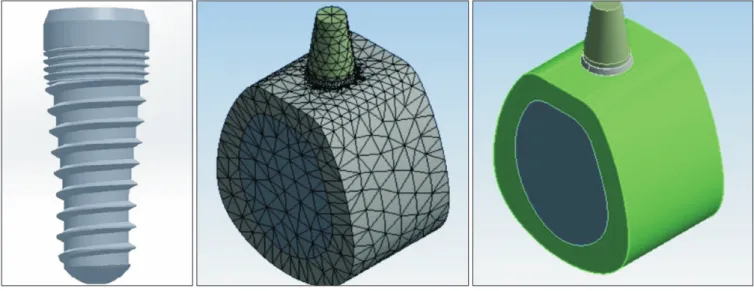
12.0.1; 2009 SAS IP, Tehran, Iran). The screw had a length of 10.5 mm and diameter of 3.8 mm. The implant neck was beveled by a 22º angle relative to the vertical axis. The im- plant neck had a height of 0.5 mm and had to remain outside of the bone. The area beneath the beveled margin had a 1 mm height with no threads and was designed to be placed in the cortical bone. The rest of the body had a specific thread design to evaluate the effect of thread design on stress distri- bution. The implant had 1.3 mm micro-threads on the upper part, and the rest of the body had V-shaped threads. In addi- thread shape. They evaluated two different implant thread
shapes and assessed the stress induced in the surrounding cortical and cancellous bone. Chang et al.7 took advantage of the topology optimization in the FE method to look for redundant material distribution on a threaded dental implant and redesigned a new implant and evaluated its biomechani- cal functions. The FE model estimated that the volume of the new implant could be reduced by 17.9% of the traditional one with the same biomechanical performance, such as stress in the implant and stress in the implant-bone complex with low- er displacement, and greater stiffness than the traditional im- plant. Shen et al.8 used bivariate analysis to determine the op- timal ranges of thread height and pitch in mini-implants and realized that maxillary stress and mini-implant stability were influenced by mini-implant thread height and pitch. Hasan et al.9 aimed to predict the distribution of bone trabeculae, as density change per unit time, around a dental implant based on a selected mathematical remodeling model. The apparent bone density change as a function of mechanical stimulus was the basis of the applied remodeling model that describes disuse and overload bone resorption. The simulation was tested in an FE model of a screw-shaped dental implant in an idealized bone segment. The analysis of sensitivity to differ- ent parameters was also performed and showed that alteration in the mechanical parameters had a significant influence on density distribution and model stability, particularly in the cortical bone. In our previous study, we assessed stress and strain patterns in cortical and cancellous bone surrounding three newly designed dental implants with different thread
Fig. 1. Implant model and the whole model.
Maryam Geramizadeh et al: Three-dimensional optimization and sensitivity analysis of dental implant thread parameters using finite element analysis. J Korean Assoc Oral Maxillofac Surg 2018
4. Optimization
Design of experiments (DOE) is generally used to effec- tively sample a design space, so that a statistical model can be built to predict responses of a given design. DOE is useful when one can only sample a limited number of points and run a limited number of simulations. The key idea of DOE is to spread out the samples so that the resultant statistical model has low uncertainty in its estimation and thus high accuracy in prediction.
The process was done by means of response surface opti- mization, which is one of the main methods of optimization in Ansys Workbench. To conduct DOE for a given model, the list of design variables and objectives of interest (input and output parameters) should be defined first. Four main pa- rameters were used as input parameters including depth and pitch of the two thread models. Each parameter has a specific range, which is input to the software. These ranges are shown in Table 2. The output parameters were maximum von-Mises stress and strain in the model, which were defined by the op- timization process.
5. Sensitivity analysis
Design sensitivity analysis plays a critical role in inverse and identification studies, as well as numerical optimiza- tion and reliability analyses13,14. The main goal of sensitivity analysis was to gain insight into critical input parameters. In this study, sensitivity analysis was also done along with the optimization process and showed more critical parameters in the model.
III. Results
The screening optimization method uses a simple approach based on sampling and sorting. It supports multiple objec- tives and constraints as well as all types of input parameters.
Usually, it is used for preliminary design, which may require additional methods for more refined optimization results. The software generates 1,000 samples (Fig. 2) and finds three tion, the implant body had an 8º taper. A fixed rigid abutment
with 5 mm height was placed on top of the screw, where the force was applied. A bone block, 17 mm high and 12 mm wide, was built around the imported implants, representing the surrounding bone in the second premolar region. A core of cancellous bone was covered with a thick layer of cortical bone with a constant thickness of 2 mm10,11. The screw model and the whole model with meshing condition are shown in Fig. 1.
2. Material properties
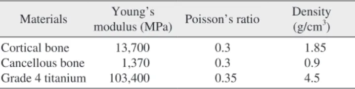
The implant was made of grade IV titanium. The behaviors of the materials were represented with linear isotropic materi- al models. The mechanical properties of the materials used in this study are shown in Table 1. All materials were assumed to be homogenous, isotropic, and linearly elastic12.
3. Finite element analysis
The physical interactions at all surfaces during loading were taken into account through bonded surface-to-surface contact features of ANSYS, and the base of the mandible was considered to be fixed. The FE model consisted of 44,922 four-node tetrahedron elements, 13,269 elements for the im- plant, 13,231 elements for the cortical bone, and 18,422 ele- ments for the cancellous bone. In this study, the implant was subjected to axial static loading of 100 N10,11.
Table 2. Input parameter ranges
Micro-thread depth (mm) Micro-thread pitch (mm) V-shaped thread depth (mm) V-shaped thread pitch (mm) Minimum
Maximum 0.25
0.3 0.27
0.33 0.405
0.495 0.66
0.8
Maryam Geramizadeh et al: Three-dimensional optimization and sensitivity analysis of dental implant thread parameters using finite element analysis. J Korean Assoc Oral Maxillofac Surg 2018
Table 1. Mechanical properties of tested materials Materials Young’s
modulus (MPa) Poisson’s ratio Density (g/cm3) Cortical bone
Cancellous bone Grade 4 titanium
13,700 1,370 103,400
0.3 0.3 0.35
1.85 0.9 4.5 Maryam Geramizadeh et al: Three-dimensional optimization and sensitivity analysis of dental implant thread parameters using finite element analysis. J Korean Assoc Oral Maxillofac Surg 2018
Sensitivity analysis was also performed in this study and indicated the most effective input parameters considering out- put parameter values. Fig. 5 shows the results obtained in this part of analysis. As shown, depth and pitch of micro-threads had greater effects on equivalent stress and strain.
candidates, which are presented in Table 3 and also shown in Fig. 3.
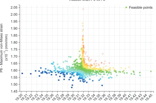
Fig. 4 shows different values of stress and strain in all itera- tions. The main goal was to minimize both parameters; thus, the green zone was desirable and optimal in this process.
0
0.05 0.10 0.15 0.20 0.25 0.30 0.35 0.40 0.45 0.50 0.55 0.60 0.65 0.70 1.45
P6-Maximumvon-Misesstress (x10)(mm/mm)3
2.00
1.90 1.85 1.80 1.75 1.70 1.65 1.60 1.55 1.50
Number of points (x10 )3 History chart of P6 (minimize P6)
1.95 2.05
0.750.800.850.900.95 1.00 History of P6 (minimize)
0
0.05 0.10 0.15 0.20 0.25 0.30 0.35 0.40 0.45 0.50 0.55 0.60 0.65 0.70 19.19
Maximumvon-Misesstrain(MPa)P5-
Number of points (x10 )3 History chart of P5 (minimize P5) 19.46
19.45 19.44 19.43 19.42 19.41 19.40 19.39 19.38 19.37 19.36 19.35 19.34 19.33 19.32 19.31 19.30 19.29 19.28 19.27 19.26 19.25 19.24 19.23 19.22 19.21 19.20
0.750.800.850.900.95 1.00 History of P5 (minimize)
Fig. 2. Iterations of solving the problem to find the perfect candidates to opti- mize the chosen parameters.
Maryam Geramizadeh et al: Three-dimensional optimization and sensitivity analysis of dental implant thread parameters using finite element analysis. J Korean Assoc Oral Maxillofac Surg 2018
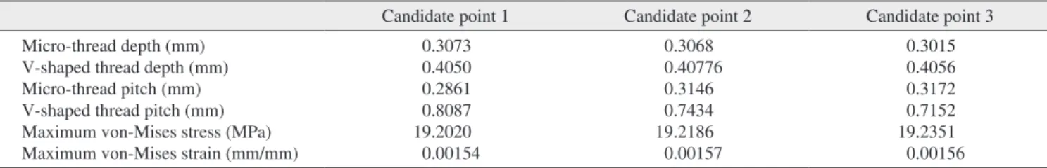
Table 3. Candidate points produced by the response surface optimization method
Candidate point 1 Candidate point 2 Candidate point 3
Micro-thread depth (mm) V-shaped thread depth (mm) Micro-thread pitch (mm) V-shaped thread pitch (mm) Maximum von-Mises stress (MPa) Maximum von-Mises strain (mm/mm)
0.3073 0.4050 0.2861 0.8087 19.2020 0.00154
0.3068 0.40776 0.3146 0.7434 19.2186 0.00157
0.3015 0.4056 0.3172 0.7152 19.2351 0.00156
Maryam Geramizadeh et al: Three-dimensional optimization and sensitivity analysis of dental implant thread parameters using finite element analysis. J Korean Assoc Oral Maxillofac Surg 2018
pattern among different screw models, and the optimal im- plant was chosen based on FEA and was a screw with micro- threads in the upper area and V-shaped threads in the rest of the body10,11.
In the present study, the main objective was to find the perfect size of the above-mentioned thread pattern. Four critical parameters were considered as input variables, which were depth and pitch of micro-threads and V-shaped threads.
Reasonable ranges were defined for these parameters, and the model was solved 1,000 times for different quantities of
IV. Discussion
Design and analysis of dental implants is an interesting topic for research. Thread-related parameters are of great im- portance due to their effects on stress and strain distribution.
Our previous studies focused on determining the best thread
Candidate point 1 Candidate point 2 Candidate point 3
0.25141 P1 (mm)
0.30728 0.49501 0.33 0.80872 19.451 2.0393
0.405 P2 (mm)
0.27 P3 (mm)
0.66166 P4 (mm)
19.202 P5 (MPa)
1.4772 P6 (x10 ) (mm/mm)
3
Candidate points
Fig. 3. Three candidate points for output results. (P1: micro- thread depth, P2: V-shaped thread depth, P3: micro-thread pitch, P4: V-shaped thread pitch, P5: maximum von-Mises stress, P6:
maximum von-Mises strain)
Maryam Geramizadeh et al: Three-dimensional optimization and sensitivity analysis of dental implant thread parameters using finite element analysis. J Korean Assoc Oral Maxillofac Surg 2018
19.2019.2119.2219.2319.2419.2519.2619.2719.2819.2919.3019.3119.3219.3319.3419.3519.3619.3719.3819.3919.4019.4119.4219.4319.4419.45 1.45
P6-Maximumvon-Misesstrain (x10)(mm/mm)3
2.00
1.90 1.85 1.80 1.75 1.70 1.65 1.60 1.55 1.50
P5 - Maximum von-Mises stress (MPa) Tradeoff chart P5 vs P6
1.95
2.05 Feasible points
Fig. 4. Consideration of stress and strain quantities to find the best points to minimize both (green zone).
Maryam Geramizadeh et al: Three-dimensional optimization and sensitivity analysis of dental implant thread parameters using finite element analysis. J Korean Assoc Oral Maxillofac Surg 2018 P1. Micro-thread depth
P2. V-shaped thread depth
P3. pitch
P4. V-shaped thread pitch Micro-thread
P5 - Maximum von-Mises stress
Sensitivity
0.35 0.30 0.25 0.20 0.15 0.10 0.05 0 0.05 0.10 0.20 0.25
Sensitivity
P6 - Maximum von-Mises strain 0.40
0.30 0.15
Output parameters
Fig. 5. Sensitivity analysis of maximum stress and strain with re- spect to the four input parameters.
Maryam Geramizadeh et al: Three-dimensional optimization and sensitivity analysis of dental implant thread parameters using finite element analysis. J Korean Assoc Oral Maxillofac Surg 2018
same as in clinical conditions. Moreover, absence of some components such as crown, which was not included in the model, may affect stress/strain patterns. In the clinical set- ting, occlusal forces are applied to a crown; in FEA, they are placed on the abutment. Therefore, FE models cannot provide absolute and realistic values of stress and strain in jawbone/
implant systems of an actual model and thus may not be quantitatively validated by a clinical study. However, for a comparative study, such simplifications are reasonable. Fu- ture studies may include friction in models as a challenging factor to obtain more realistic results. Changing the angles of the taper and bevel may yield more accurate results and can be evaluated in further studies.
V. Conclusion
Based on the results of this study, the optimal dental im- plant design has micro-threads with 0.307 and 0.286 mm depth and pitch, respectively, in the upper area and V-shaped threads with 0.405 and 0.808 mm depth and pitch in the rest of the body. This model may result in optimal stress distribu- tion and subsequently better osseointegration and greater du- rability. In addition, it has been concluded that micro-thread parameters have greater effects on stress and strain values, which proves that the upper area in implants is more im- portant than the rest of the body. This conclusion was made based on sensitivity analysis in FEA.
ORCID
Maryam Geramizadeh, http://orcid.org/0000-0002-0003-6447 Hamidreza Katoozian, http://orcid.org/0000-0001-6317-572X Reza Amid, http://orcid.org/0000-0002-8053-3928
Mahdi Kadkhodazadeh, http://orcid.org/0000-0002-6131-2791
Authors’ Contributions
M.G. participated in data collection and wrote the manu- script, participated in the study design and performed the statistical analysis. H.K., R.A., and M.K. participated in the study design and coordination and helped to draft the manu- script.
Conflict of Interest
No potential conflict of interest relevant to this article was reported.
input parameters in these ranges to find the perfect output parameters. This process took a few hours, and the solutions are shown in Fig. 2. The software produces three candidate points that have the best results based on the given informa- tion. The characteristics of these points are presented in Fig.
3 and Table 2 for the purpose of comparison. The optimal an- swer can be chosen from these candidate points. In this study, candidate point number 1 was chosen due to smaller stress and strain values. Fig. 4 shows the two output parameters.
The software was asked to minimize both parameters, so the green zone was acceptable for the purpose of this study.
Design sensitivity analysis plays an important role in all engineering design processes. In this study, this analysis was also considered carefully to have a better understanding of the effectiveness of different design parameters. The results of such analysis help researchers to focus on important pa- rameters. This model showed that micro-thread size was im- portant and has large effects on stress and strain distribution.
Micro-threads are designed in the upper area of the implant, which is in contact with cortical bone. This part experiences the most stress, especially at the contact point of first thread with cortical bone. This conclusion had been reached in pre- vious studies10,11. In this study, sensitivity analysis proved the importance of the mentioned area, which receives the highest load and needs to be considered carefully in dental implant designs.
There are some limitations as well as simplifications in FEA, which limit the generalization of results to the clini- cal setting. For example, the force of the tongue and other muscles in the oral cavity is not taken into account in FEA, and abutment is considered to be rigid and fixed, which is not true in a clinical setting. In addition, the micro-movements of the abutment may affect the clinical results long-term. In FEA, loading conditions are not exactly the same as in the clinical situation, since they vary in males and females and in different chewing conditions. Also, loading is considered to be static in this study despite the dynamic nature of applied loads in the clinical setting. Another important factor is the quality of the jawbone, which is not the same in all individu- als and may even vary in the same individual in different areas. In the current study, the jawbone was assumed to be isotropic and homogenous in FEA, which is not the case in vivo and may be responsible for the differences in results compared to those obtained in the clinical setting and with other FEA using different bone quality assumptions.
The implant-cortical/cancellous bone interface was com- pletely bonded in the present study, although it was not the
References
1. Gosavi SP, Dhatrak PN, Narkar KM. Optimisation of dental im- plant. Int Eng Res J 2015;3:4319-23.
2. Brunski JB. Biomaterials and biomechanics in dental implant de- sign. Int J Oral Maxillofac Implants 1988;3:85-97.
3. Mahajan S, Patil R. Application of finite element analysis to opti- mizing dental implant. Int Res J Eng Technol 2016;3:850-6.
4. Kong L, Zhao Y, Hu K, Li D, Zhou H, Wu Z, et al. Selection of the implant thread pitch for optimal biomechanical properties: a three- dimensional finite element analysis. Adv Eng Softw 2009;40:474- 5. Petrie CS, Williams JL. Shape optimization of dental implant 8.
designs under oblique loading using the p-version finite element method. J Mech Med Biol 2002;3:339.
6. Shi L, Li H, Fok AS, Ucer C, Devlin H, Horner K. Shape optimiza- tion of dental implants. Int J Oral Maxillofac Implants 2007;22:911- 7. Chang CL, Chen CS, Huang CH, Hsu ML. Finite element analysis 20.
of the dental implant using a topology optimization method. Med Eng Phys 2012;34:999-1008.
8. Shen S, Sun Y, Zhang C, Yang Y, Li Z, Cai X, et al. Bivariate opti-
mization of orthodontic mini-implant thread height and pitch. Int J Comput Assist Radiol Surg 2015;10:109-16.
9. Hasan I, Rahimi A, Keilig L, Brinkmann KT, Bourauel C. Com- putational simulation of internal bone remodelling around dental implants: a sensitivity analysis. Comput Methods Biomech Biomed Engin 2012;15:807-14.
10. Geramizadeh M, Katoozian H, Amir R, Kadkhodazadeh M. Static, dynamic, and fatigue finite element analysis of dental implants with different thread designs. J Long Term Eff Med Implants 2016;26:347-55.
11. Geramizadeh M, Katoozian H, Amid R, Kadkhodazadeh M. Finite element analysis of dental implants with and without microthreads under static and dynamic loading. J Long Term Eff Med Implants 2017;27:25-35.
12. Seong WJ, Kim UK, Swift JQ, Heo Y, Hodges JS, Ko CC. Elastic properties and apparent density of human edentulous maxilla and mandible. Int J Oral Maxillofac Surg 2009;38:1088-93.
13. Tortorelli DA, Michaleris P. Design sensitivity analysis: overview and review. Inverse Probl Eng 1994;1:71-105.
14. Kayabaşı O, Yüzbasıoğlu E, Erzincanlı F. Static, dynamic and fa- tigue behaviors of dental implant using finite element method. Adv Eng Softw 2006;37:649-58.