http://dx.doi.org/10.6111/JKCGCT.2013.23.2.67
Design optimization of the outlet holes for bone crystal growing with bio- active materials in dental implants: Part I. cross-sectional area
Yong Keun Lee and Kangsoo Lee*,†
Graduate School of NID Fusion Technology, Seoul National University of Science and Technology, Seoul 139-743, Korea
*Department of Advanced Materials Engineering, Kyonggi University, Suwon 443-760, Korea (Received January 21, 2013)
(Revised March 11, 2013) (Accepted March 15, 2013)
Abstract In order to improve osseo-integration of a dental implant with bone crystal we studied an implant with holes inside its body to deliver bioactive materials based on a proposed patent. After bioactive material is absorbed, bone crystal can grow into holes to increase implant bonding in addition to surface integration. The larger cross section area of outlet holes showed the less values of the maximum stress, and the stress concentrations near the uppermost outlet holes were also reduced with an increasing number of outlet holes. The conclusion, that the uppermost outlet design improvement was most effective to reduce the stress concentration and improve the growth rate of bone crystal, could be drawn. After the design optimizations, Type 6-C had provided the best results in this study. The overall shape optimization studies on the shape, location, number, and so on, of the outlet holes, should be carried out further.
Key words Bone crystal, Dental implant, Finite element, Bioactive material, Outlet holes
1. Introduction
A dental implant is an artificial tooth root used in dentistry to support restorations that resemble a tooth or group of teeth [1]. Dental implants can be used to sup- port a number of dental prostheses, including crowns, implant-supported bridges or dentures [2-4]. In order to lengthen the lifetime of implants and accelerate the bone crystal healing process, some research focuses on improving the initial anchorage of the implant as well as preserving the strength of the bone crystal to implant interface. However, none of these current approaches are satisfactory. Bone crystal is formed from carbonated hydroxyapatite with lower crystallinity. Bone crystal is formed from globular and plate structures, distributed among the collagen fibrils of bone and forming yet a larger structure [5].
The encapsulated biological agents are loaded into the hollow and porous implant and promote the growth of new bone crystal or tooth structures. The combination of porosity and controlled release techniques produce a new dental and/or orthopedic implant system that accel- erates bone crystal ingrowth and osseointegration (inte- gration of, e.g. titanium into host bone crystal or teeth).
The controlled release technology delivers scheduled doses of growth factors and/or other chemical and/or pharmacological substances in a pre-defined temporal and spatial manner to promote bone crystal ingrowth and/or osseointegration. The physical signs of the pores and hollow cylinder can be altered to optimize bone crystal ingrowth and/or osseointegration.
The majority of dental implants currently available are shaped like small screws, with either tapered or parallel sides. They can be placed at the same time as a tooth is removed by engaging with the bone crystal of the socket wall and sometimes also with the bone crystal beyond the tip of the socket. Current evidence suggests that implants placed straight into an extraction socket have success rates comparable to those placed into healed bone crystal [6, 9]. The success rate and radio- graphic results of immediate restorations of dental implants placed in fresh extraction sockets (the tempo- rary crowns placed at the same time) have been shown to be comparable to those obtained with delayed load- ing (the crowns placed weeks or months later) in care- fully selected cases [7].
A typical implant consists of a titanium screw (resem- bling a tooth root) with a roughened or smooth surface.
The majority of dental implants are made out of com- mercially pure titanium, which is available in 4 grades depending upon the amount of carbon and iron con- tained. More recently grade 5 titanium has increased in
†Corresponding author
†Tel: +82-31-249-1379
†Fax: +82-10-7767-3157
†E-mail: [email protected]
use. Grade 5 titanium, Titanium 6AL-4V, is believed to offer similar osseointegration levels as commercially pure titanium. Ti-6Al-4V alloy offers better tensile strength and fracture resistance. Today most implants are still made out of commercially pure titanium (grades 1 to 4) but some implant systems are fabricated out of the Ti-6Al- 4V alloy. Implant surfaces may be modified by plasma spraying, anodizing [8], etching or sandblasting to increase the surface area and the integration potential of the implant.
An implant, be it dental, orthopedic or other, is usually a biologically compatible material, like titanium, which is surgically inserted within the body to replace defective structures such as bone crystal or teeth. Although these implants become more commonplace, problems still remain in the area of osseointegration, in both immedi- ate and long-term view. Most implant procedures focus mainly on mechanical repair without much thought as to regeneration of bone crystal. It has been shown that the replacement of bone crystals such as hip joints that ini- tially osseointegrate properly deteriorate years later because of osteolysis at implant interfaces.
The aim of this study is to confirm the changes of the maximum stress at the outlet holes by increasing the
size and the number of outlet holes or by changing the shape or location of outlet holes, and identify the corre- lation between the design elements and the mechanical properties. These results of this study will be used to obtain the transient solutions considering shape optimi- zations and bioactive factors.
2. Research Procedure
2-dimensional (2-D) simulation was used in the first phase of the study [10], which include the structural properties of an implant and holes, the effect of bioactive material on stress distribution, and properties of holes such as location, shape, and the number. The diameters of 0.2 to 1 mm and 0.2 to 2 mm were studied for an inlet and an outlet of a hole, respectively. Locations of inlets, outlets, and connecting holes were varied to opti- mally re-distribute and reduce stress on an implant. The number of outlets was varied between 2 to 5. The sec- ond phase of the study will improve the results obtained from the first phase with 3-dimentional (3D) structural design. In order to accomplish this goal, 3D model was developed to accommodate the 2D analysis, and the
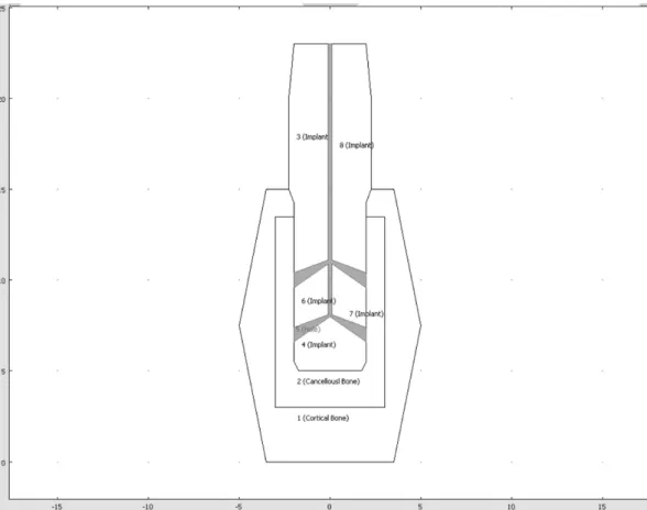
Fig. 1. Type 5-E, 5 Grooves with 4 cone-shaped outlet holes (0.2 mm inlet and 0.8 mm outlet diameter).
analyses will be conducted with a situation when bone crystals fill those holes from outlets. 3D simulation method includes specific requirements for implant administration and improves 3D models to be applica- ble for diverse patients. In the final phase, the study will include bone crystal growth progress with biological factors such as mechanical properties of bone crystal growing around and inside of an implant. Time depen- dent or specific data is integrated into the simulation method. The resulting transient simulation method will be used in together with clinical data to finalize our implant design.
3. Results and Discussion
For the comparison with the previous results, the
Table 1
Mechanical properties of the material used
Young’s Modulus (GPa) Poisson’s ratio
Cortical bone crystal 20 0.3
Cancellous bone crystal 2 0.2
Implant fixture (Titanium Beta-215) 105 0.33
Cortical and cancellous bone crystal compound filling holes 14 0.27
Fig. 2. Type 5-E, 9778 Triangular elements mesh generation.
same number of injection and outlet holes (1 injection and 4 outlet holes) were used, but the cone-shaped out- let holes were considered to increase the cross-sectional area of the outlet holes (Fig. 1). Triangular elements were used to make a mesh, and implanted and outlet areas had dense elements for more accurate analysis.
Models consisted of 9,778 elements for an implant with one inlet and four outlets. Titanium beta-215 was used to model an implant fixture (Table 1). We assumed that bone crystals grow and fill the holes after bioactive material is applied if it was absorbed and leaved holes.
In this case the bone crystals filling the holes are assumed to be compound of both cortical and cancel- lous bone crystals. Since this situation was not reported yet, the mechanical property of this compound was determined by the surface ratio of cortical and cancel- lous bone crystals. Loads applied in the analysis was set
Fig. 4. Type 6-A, 6 Grooves with 5 cone-shaped outlet holes (0.4 mm inlet and 1.0 mm outlet diameter).
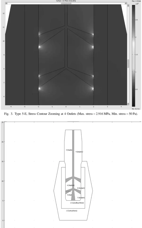
Fig. 3. Type 5-E, Stress Contour Zooming at 4 Outlets (Max. stress = 2.916 MPa, Min. stress = 50 Pa).
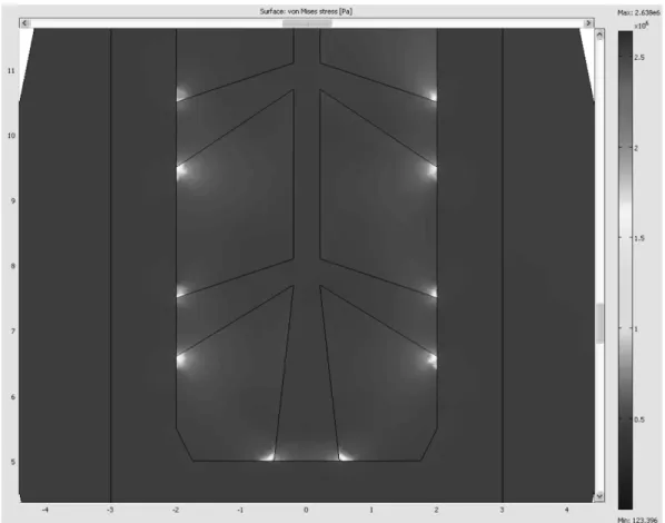
Fig. 5. Type 6-A, Stress Contour Zooming at 5 Outlets (Max. stress = 2.638 MPa, Min. stress = 123 Pa).
to be 400 N/m downward and 75 N/m right, which was a bit greater than those usually applied in a real patient.
The load was set to be evenly distributed in the upper part of the implants.
Boundary conditions are like this.
On the top of Implant Loading Fy=−400 N/m Fx= 75 N/m At the boundary of implant contact
cancellous bone crystal Dx= 4e−6m
At 4 outlet holes Fixed
In the stress contour of Fig. 3, the maximum stress value was reduced by 23% from 3.809 MPa (Type 5-D with 0.2 mm outlet diameter) to 2.916 MPa (Type 5-E with 0.8 mm outlet diameter), the stress concentration near outlet holes was also spread out over a little more wide area in the surface plot. However, still more than 10 times of stress concentration occurred as compared with the case without the strengthening effect at the out- let, and so steady design improvements in the direction of increasing the contact areas between the cancellous bone crystal and the implant are necessary. In Fig. 4, the cross-sectional area was increased by 144% from (0.4 ×
4)2= 2.56 (Type 5-E with 0.8 mm outlet diameter) to (0.5 × 5)2= 6.25 (Type 6-A with 1.0 mm outlet diame- ter and one more outlet hole at the bottom). However, it was necessary to increase the inlet hole diameter from 0.2 mm to 0.4 mm in order to reduce the probability of the bottleneck phenomenon while injecting the bioactive materials. In the stress contour of Fig. 5, the maximum stress value was reduced by 9.5% from 2.916 MPa (Type 5-E with 0.8 mm outlet diameter) to 2.638 MPa (Type 6-A with 1.0 mm outlet diameter and one more outlet hole at the bottom). Moreover, the stress concen- tration near outlet holes was also reduced and spread out over a more wide area.
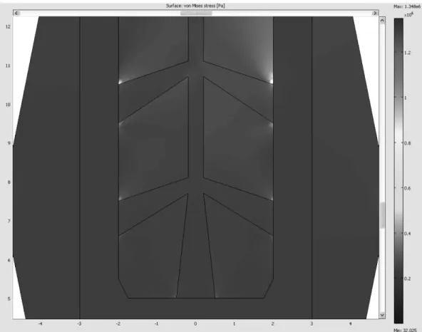
In the stress contour of Fig. 6, the maximum stress value was reduced from 2.638 MPa (Type 6-A with 1.0 mm outlet diameter and one more outlet hole at the bottom) to 1.348 MPa (Type 6-B, same as Type 6-A, but bound- ary condition Dx = 0), and the maximum stress value was reduced by 23% from 1.757 MPa (Type 5-B with the first strengthening effect by the bioactive materials) to 1.348 MPa (Type 6-B, same as Type 6-A, but bound- ary condition Dx = 0). 1.0 mm outlet diameter and one more outlet hole at the bottom) to 1.348 MPa (Type 6- B, same as Type 6-A, but boundary condition Dx = 0).
However, it is still more than 7.5 times of the maxi- mum stress value as compared with the case without the strengthening effect by the bioactive materials (Type 5- A, the maximum stress value = 0.1807 MPa). In Fig. 6,
the stress concentrations at the outlet holes disappeared except at the uppermost outlet hole. As shown in Fig. 7, the stress distributed along the cross-sectional line that crosses the right outlet holes, and the stress concentra- Fig. 7. Type 6-B, Stress graph on the cross section (along with the Red line).
Fig. 6. Type 6-B, Stress Contour Zooming at 5 Outlets (Max. stress = 1.348 MPa, Min. stress = 32 Pa).
tion was decreased dramatically farther away from the uppermost outlet hole. The stress concentration at the top right occurred in the direction of resultant force of the given boundary condition (plus X direction and
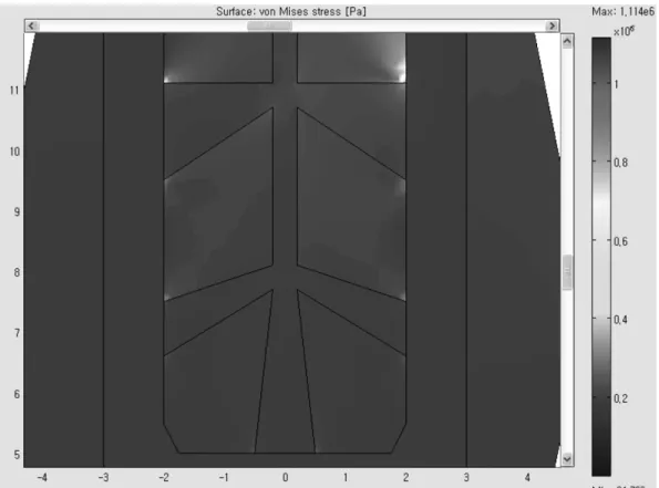
Fig. 9. Type 6-C, Stress Contour Zooming at 5 Outlets (Max. stress = 1.114 MPa, Min. stress = 24 MPa).
Fig. 8. Type 6-C, 6 Grooves with 5 cone-shaped outlet holes with bigger cross-sectional area for top two outlet holes. (0.4 mm inlet and 1.6 mm/1.0 mm outlet diameters).
minus Y direction loads), and the similar stress concen- tration at the top left is expected with the boundary con- dition (minus X direction and minus Y direction loads).
The horizontal direction load was the larger stress con-
centration factor than the vertical direction load, and thus the cross-sectional area of the top two outlet holes is necessary to be increased dramatically in order to absorb the loads in the X direction.
In Fig. 8, the cross-sectional area was increased by 62% from 3.9250 mm2 (Type 6-B with 1.0 mm outlet diameter) to 6.3742 mm2 (Type 6-C with 1.6 mm upper- most outlet diameter and one more outlet hole at the bottom). In the stress contour of Fig. 9, the maximum stress value was reduced by 17% from 1.348 MPa (Type 6-B with 1.0 mm outlet diameter) to 1.114 MPa (Type 6-C with 1.6 mm uppermost outlet diameter and one more outlet hole at the bottom), and reduced by 37%
from 1.757 MPa (Type 5-B) to 1.114 MPa (Type 6-C).
This was a remarkable result, compared to 23% reduc- tion from 1.757 MPa (Type 5-B) to 1.348 MPa (Type 6- B). It is concluded from these results that the upper- most outlet design improvement was more effective to
reduce the stress concentration.
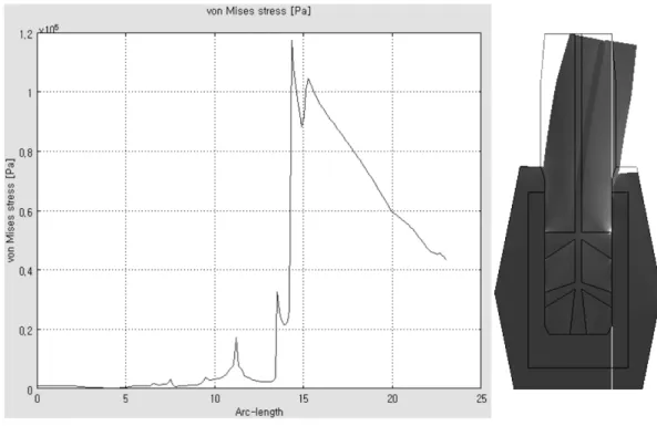
As shown in Fig. 10, the stress distributed along the cross-sectional line that crosses the right outhlet holes, and the stress concentration was decreased dramatically farther away from the uppermost outlet hole. These results were summarized in Table 2.
4. Conclusions
The larger cross sectional area of outlet holes results in the less value of the maximum stress, and the stress concentrations near the uppermost outlet holes are also reduced with an increasing number of outlet holes. It is concluded that the uppermost outlet design improve- ment is the most effective way to reduce the stress con- centration and improve the growth rate of bone crystal.
It is a consistent conclusion, considering the loads in the Table 2
Max. stress with cross-sectional area variations of inlet and outlets Type
(# of Groove)
Size of inlet (mm)
Size of 2 top outlet (mm)
Size of 2 middle outlet (mm)
Size of 1 bottom outlet (mm)
Total area of outlets (mm2)
Extra B.C.
Dx (mm)
Max stress (MPa)
5-B 0.2 0.2 0.2 0 0.13 0 1.757
5-D 0.2 0.2 0.2 0 0.13 0.0004 3.809
5-E 0.2 0.8 0.8 0 2.01 0.0004 2.916
6-A 0.4 1.0 1.0 1.0 3.93 0.0004 2.638
6-B 0.4 1.0 1.0 1.0 3.93 0 1.348
6-C 0.4 1.6 1.0 1.0 6.38 0 1.114
Fig. 10. Type 6-C, Stress graph on the cross section (showing with Red line).
boundary conditions. After the design optimizations, Type 6-C is the best design in our study. Type 6-C with design of three cone-shaped outlet holes (0.4 mm inlet diameter and 1.0 mm outlet diameter) and two larger cross-sectional area of the upper outlet holes (0.4 mm inlet diameter and 1.6 mm outlet diameter) shows the lowest value and dramatic decrease of stress concentra- tion farther away from the uppermost outlet holes. The overall design optimization of the shape, locations and the numbers of holes is necessary for further study.
Acknowledgement
This study was financially supported by Seoul National University of Science & Technology.
References
[ 1 ] P.I. Bra°nemark, “Osseointegration and its experimental background”, J. Prosthet. Dent. 50 (1983) 399.
[ 2 ] L.A. Weinberg and B. Kruger, “Biomechanical consider- ations when combining tooth-supported and implant- supported prostheses”, Oral Surg. Oral Med. Oral Pathol. 78 (1994) 22.
[ 3 ] D.C. Holmes, W.R. Grigsby, V.K. Goel and J. C. Keller,
“Comparison of stress transmission in the IMZ implant system with polyoxymethylene or titanium intramobile element: a finite element stress analysis”, Int. J. Oral Maxillofac. Implants 7 (1992) 450.
[ 4 ] B. Rangert, T. Jemt and L. Jorneus, “Forces and moments on Bra°nemark implants”, Int. J. Oral Maxillofac.
Implants 4 (1989) 241.
[ 5 ] S. Bertazzo and C.A. Bertran, “Morphological and dimensional characteristics of bone mineral crystals”, Bioceramics 18 (2006) 7.
[ 6 ] M. Quirynen, N. Van Assche, D. Botticelli and T. Ber- glundh, “How does the timing of implant placement to extraction affect outcome?” Int. J. Oral Maxillofac.
Implants 22 Suppl. (2007) 203.
[ 7 ] R. Crespi, P. Capparé, E. Gherlone and G.E. Romanos,
“Immediate versus delayed loading of dental implants placed in fresh extraction sockets in the maxillary esthetic zone: a clinical comparative study”, Int. J. Oral Maxillofac. Implants 23 (2008) 753.
[ 8 ] R. Palmer, “Ti-unite dental implant surface may be superior to machined surface in replacement of failed implants”, J. Evid. Base. Dent. Pract. 7 (2007) 8.
[ 9 ] J.K. Lee, Y.H. Ko and N.H. Lee, “Biocompatibility of porous hydroxyapatite ceramics prepared from bovine bones”, J. Kor. Cryst. Growth Cryst. Tech. 22 (2012) 139.
[10] S.J. Lim, H.Y. Shin, J.H. Kim and J.I. Lim, “Finite ele- ment analysis for czochralski growth process of sap- phire single crystal”, J. Kor. Cryst. Growth Cryst. Tech.
21 (2011) 193.