Introduction
Ever since the first dental implants have been introduced by Branemark et al1in 1969, more than four decades ago, dental practitioners and researchers have been searching for various methods for improving the accuracy of the sur- gical placement of implants. Advances in dental imaging technology utilizing computed tomography (CT) has been proven especially useful when determining the installation
sites of dental implants.2-8However, even though the CT images may provide accurate anatomical information of the jaws, the final decision is performed by the surgeon placing the implants.2-8 Therefore, the operator’s experi- ence and skills become a critical factor in successful im- plant therapy, and for those surgeons lacking sufficient expertise for specific clinical situations, positioning and installing implant fixtures often become highly arduous tasks.2-8To cope with the problem, more attention is now being paid to image-guided implantology, which is design- ed to aid surgeons when performing implant treatments.9-12
Currently, one of the most popular systems is based on the CAD/CAM concept, which produces a 3-dimensional (3D) rapid processing (RP) jaw model with 3D CT imaging, and fabricates surgical stents for this RP model.13Though
In-vitro study on the accuracy of a simple-design CT-guided stent for dental implants
Young-June Huh, Bo-Ram Choi, Kyung-Hoe Huh, Won-Jin Yi*, Min-Suk Heo, Sam-Sun Lee*, Soon-Chul Choi
Department of Oral and Maxillofacial Radiology and Dental Research Institute, School of Dentistry, Seoul National University, Seoul, Korea
*Department of Oral and Maxillofacial Radiology, Dental Research Institute and BK21 Craniomaxillofacial Life Science, School of Dentistry, Seoul National University, Seoul, Korea
ABSTRACT
Purpose: An individual surgical stent fabricated from computed tomography (CT) data, called a CT-guided stent, would be useful for accurate installation of implants. The purpose of the present study was to introduce a newly devel- oped CT-guided stent with a simple design and evaluate the accuracy of the stent placement.
Materials and Methods: A resin template was fabricated from a hog mandible and a specially designed plastic plate, with 4 metal balls inserted in it for radiographic recognition, was attached to the occlusal surface of the template.
With the surgical stent applied, CT images were taken, and virtual implants were placed using software. The spatial positions of the virtually positioned implants were acquired and implant guiding holes were drilled into the surgical stent using a specially designed 5-axis drilling machine. The surgical stent was placed on the mandible and CT images were taken again. The discrepancy between the central axis of the drilled holes on the second CT images and the virtually installed implants on the first CT images was evaluated.
Results: The deviation of the entry point and angulation of the central axis in the reference plane were 0.47±0.27 mm, 0.57±0.23 mm, and 0.64±0.16。, 0.57±0.15。, respectively. However, for the two different angulations in each group, the 20。angulation showed a greater error in the deviation of the entry point than did the 10。angulation.
Conclusion: The CT-guided template proposed in this study was highly accurate. It could replace existing implant guide systems to reduce costs and effort. (Imaging Sci Dent 2012; 42 : 139-46)
KEY WORDS: Computer-Assisted Diagnosis; Dental Implant; Tomography, X-Ray Computed; In Vitro
*This study was supported by the research grant No. 03-2005-001 from the Seoul National University Dental Hospital Research Fund.
Received March 20, 2012; Revised June 1, 2012; Accepted June 16, 2012 Correspondence to : Prof. Soon-Chul Choi
Department of Oral and Maxillofacial Radiology, School of Dentistry, Seoul National University, 28 Yeongeon-dong, Jongno-gu, Seoul 110-768, Korea
Tel) 82-2-2072-2622, Fax) 82-2-744-3919, E-mail) [email protected]
http://dx.doi.org/10.5624/isd.2012.42.3.139
Copyright ⓒ 2012 by Korean Academy of Oral and Maxillofacial Radiology
This is an Open Access article distributed under the terms of the Creative Commons Attribution Non-Commercial License (http://creativecommons.org/licenses/by-nc/3.0) which permits unrestricted non-commercial use, distribution, and reproduction in any medium, provided the original work is properly cited.
Imaging Science in Dentistry∙pISSN 2233-7822 eISSN 2233-7830
this stent, leaving a hole in the position for fixture installa- tion, may be advantageous in placing implants precisely, it has its setbacks due to the complex procedures required, errors during RP model fabrication, and high costs.14,15A modified system aimed to reduce costs and effort was pro- posed, which attached a framework to the patient’s face prior to taking CT images and setting the stent holes on the basis of this framework.16,17 However, it was inconv- enient to use and there were possible errors during the fixa- tion of the framework on the patient’s face. Pongracz and his coworkers developed a software program, allowing intuitive treatment plans using 3D CT images.18With the software, both virtual planning and virtual surgery were made possible. However, transferring virtual information to actual operations had many shortcomings. Koulechov and Lueth proposed tracing the position of an operative drill for automated implant surgery.19This method showed high accuracy in tracing drill position with very limited errors, but its use in the oral cavity was restricted due to the large tracking devices attached to the drills. Another method used radiopaque markers inserted into the dentures of the patients, and CT images were taken to place guide holes based on the marker locations of the dentures. How- ever, this method was only applicable to patients with com- plete dentures, and produced potential errors from ill-fitting dentures.20
So far, CT-guided template production techniques have been either inclined toward precision, or focused on feasi- bility regarding costs and easy application. It is necessary to develop a method with both high accuracy and feasibility for clinical settings.
The purpose of the present study was to evaluate the accuracy of a newly developed CT-guided surgical stent with a simple design.
Materials and Methods
A hog dry mandible, with a molar extracted on each side, was used throughout the experiment for surgical stent fab- rication and CT image taking. An impression of the mandi- ble including the alveolar bone and teeth was taken, using silicone rubber impression material (Fegura-Sil hydro spe- zial II, Feguramed GmbH, Buchen, Germany) and an im- pression tray made with baseplate wax. From this impres- sion, a stone cast was prepared. On the stone cast, an occlu- sal stent that registered the occlusal surface of the hog’s teeth was fabricated using a resin plate according to com- mon clinical protocol. With the stent applied, the edentu- lous area of the mandible was filled with resin up to the
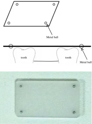
level of the occlusal surface of the adjacent teeth. On the edentulous area of the occlusal stent, a specially designed plastic plate (20×35×2 mm) was attached to serve as a reference plane on CT images. For radiographic recogni- tion, a metal ball (2 mm in diameter) was inserted in each of the 4 corners of the plate 2 mm apart from the edge of the plate (Fig. 1).
CT images of the hog mandible, with the surgical stents applied on both sides, were taken using a multi-detector spiral CT machine (Somatom Sensation 10, Siemens, Erl- angen, Germany). The conditions of the CT images were as follows: Slice thickness of 0.75 mm, 120 kVp, 100 mAs, gantry 0�, 0.254 pixel spacing, and reconstruction interval of 0.6 mm. The CT images were saved in DICOM format, and the data were transferred to the V-Implant (Cybermed, Seoul, Korea) software.
Reformatted and recombinant images including panora- mic, cross-sectional, and 3D images as well as axial images were acquired from the CT data. The positions and direc- tions of the implants were planned using the additional
Metal ball
Metal ball
tooth tooth
Fig. 1.Plastic plate for determination of a reference plane. For ra- diographic recognition, 4 metal balls (2 mm in diameter) are insert- ed in each of the 4 corners of the plate 2 mm away from the edge of the plate.
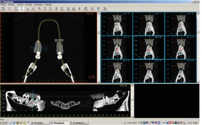
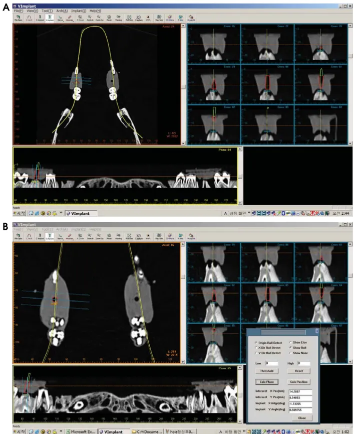
functions of the V-Implant software. The software expressed numerically the spatial position of the virtual implant axis with the coordinates of the insertion point and the angle relative to the reference plane. The reference plane on the CT images was determined by connecting the center of the radiopaque metal balls in the plastic plate. The procedure determining the center of the metal balls and the resultant reference plane was automatically performed by the soft- ware. The data of the spatial positions for the virtually installed implants were recorded in the software (Fig. 2).
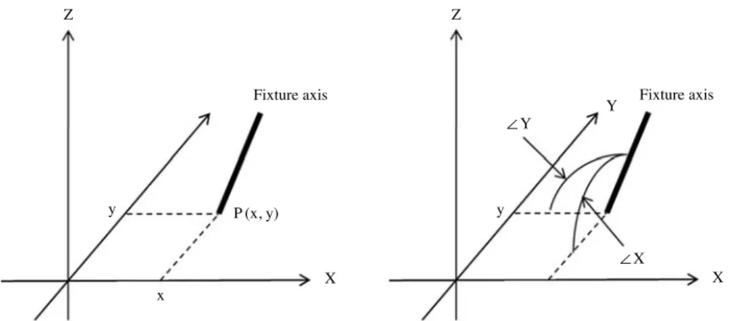
The detailed procedure calculating the spatial position of the central axis of the virtually installed implant was as follows. The line connecting the 2 metal balls aligned to the long axis on the plastic plate was set as the X-axis, and the other line aligned to the short axis was set as the Y- axis. The point of intersection was set as the datum point O, thereby constituting the XOY-plane (Fig. 3). The X and Y coordinates of an insertion point P(x, y) was determined by the crossing point between the axis of the virtual implant and the XOY-plane, and the angle between the axis of the virtual implant and the XOY-plane was determined as Xθ and Yθ according to the X-axis and Y-axis, respectively (Figs. 4 and 5).
The virtual installation of implants was performed with five different inclinations from the occlusal plane, i.e., per-
pendicular, buccal, lingual, mesial, and distal. Each incli- nation but the perpendicular one had two different angula- tions, 10�and 20�. Thus, the planned implants were divided into 9 groups according to their axis inclination and angu- lation. For each group, 10 fixtures were placed, 5 on each side (5 on the right side of the mandible, 5 on the left side of the mandible). Therefore, a total of 90 fixtures were virtually inserted.
The data of the virtually installed fixtures as mentioned above were transferred to a specially designed 5-axis dril-
Fig. 2.Implant planning procedure using V-Implant software.
Y′
O′ X′
X
O X O Y
Fig. 3.The reference XOY-plane determined on the plastic plate to calculate the relative position and angulation of the virtual implant.
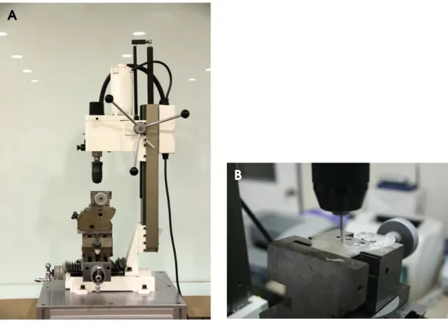
ling machine (Fig. 6A) and the implant guiding holes were drilled into each surgical stent. The drilling procedure was as follows: The plastic plate, used as a reference plane, of the surgical stent was fixed parallel to the table of the dril- ling machine. By moving and rotating the table of the mach- ine, which can control the position and angulation of the table by rotating each of its 5 axes, the spatial position of each virtual implant axis was reproduced on the table of the machine. Finally, guide holes were drilled into each of
the surgical stents (Fig. 6B). A total of 90 surgical stents, each with a guide hole (9 groups according to the inclina- tion and angulation of the virtual implant axis, and 10 stents for each group), were drilled.
After applying the stents to the hog mandible, CT images were taken under the same conditions as taken previously.
The spatial position of the drilled holes was acquired on the software. The procedure for determining the spatial position of the drilled holes was as follows: The drilled
Fig. 5.At the insertion points P (x, y), ∠X (Xθ) and ∠Y (Yθ) are calculated automatically by the software.
Fig. 4.These illustrations show the procedure for the determination of the position and angle of the virtual implant. The insertion point P (x, y) is determined by the crossing point between the axis of the virtual implant and the XOY-plane, and ∠X (Xθ) and ∠Y (Yθ) are defined as the degree from the X- and Y-axis, respectively.
Z Z
X
∠X
∠Y
Y
P (x, y)
Fixture axis Fixture axis
y y
x
X
guide hole was shown as a black cylindrical area on the CT images, and placing a virtual implant into the guide hole was performed on the software (Fig. 7A). After con- firming the virtually positioned implant to be placed exactly into the image of a guide hole, the position and the angu- lation of the central axis of the guide hole were calculated automatically by the software (Fig. 7B).
The spatial positions of the drilled holes were then com- pared with those of the virtually installed implant in the planning phase. The discrepancy between them was cal- culated and recorded as the amount of error for this system.
Results
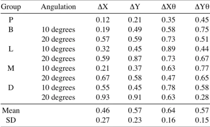
Table 1 shows the discrepancy of the X, Y coordinates and the angulation for each group. The insertion point of the implant axis on the plate was described as the X and Y coordinates.
The discrepancy of the insertion point P (x, y) ranged from 0.12 mm to 0.93 mm on the X-axis and from 0.21 mm to 0.91 mm on the Y-axis. The discrepancy of insertion angulations to the XOY-plane (Xθ, Yθ) ranged from 0.35
to 0.89 on the X-axis and from 0.45 to 0.77 on the Y-axis.
The mean values of ΔX, ΔY, ΔXθ, and ΔYθ were 0.46 mm, 0.57 mm, 0.64�, and 0.57�, respectively.
For the two different angulations in each group, 20 degree angulation showed a greater error in the deviation of the insertion point P (x, y) than 10 degree angulation, but not in the discrepancy of the angle.
Discussion
The present system used a plastic plate with metal balls to determine the reference plane, and the procedure is rela- tively simple and performed commonly in dental clinics.
Even though the procedure was simple and cost-effective, the resultant stent still provided an accurate template.
Previous studies have shown that, in general, the accu- racy of implant placement using surgical stents will be higher than that of implant placement without stents. How- ever, its accuracy will depend mostly on the operator’s technique.21,22Recently, several studies using objective numerical values have been conducted to evaluate the accu- racy of implant guiding systems, specifically, the quanti-
A
B
Fig. 6.A. The specially designed 5-axis drill machine. B. By moving and rotating the table of the machine, a guide hole is made reflecting the determined implant axis.
fied accuracy of automatic position-trace systems. Wid- mann et al evaluated the accuracy of automatic position
tracing system based on deviation from the reference point, and the average error was 0.42±0.26 mm (1 mm maxi-
Fig. 7.A. The guide hole is shown as the black cylindrical area on the CT image. The virtual implant is placed into the guide hole on the software. B. After confirming the virtually positioned implants to be placed exactly into the guide hole, the position and the angulation of the central axis of the implant are calculated.
A
B
mum).23 Brief et al used a coordinate measuring device called the ‘Faro arm’, and they reported an error of 0.60 mm and 2.12�.24 Using mutual information registration, which evaluated the deviation of the fixture position by superimposing CT images before and after the surgery, Wanschitz et al reported that the accuracy was 0.96±0.72 mm (range 0.0-3.5 mm).25Van Steenberghe et al inserted zygoma implants using a 3D CT system and reported that angulation errors of most implants were not greater than 3�and that the largest error was 2.7 mm.26The deviation of the entry point and angulation for the system proposed in the present study were 0.47±0.27 mm, 0.57±0.23 mm, 0.64±0.16。, and 0.57±0.15�, respectively, and this shows that this system is highly accurate. The range of errors acquired from the present study were similar to, or more accurate than, those obtained from previous studies.
We attempted to exclude the errors that may have been caused by surgeons and only focused on evaluating the in vitro accuracy of the guide holes of the stents. However, any possible accidental errors that may have occurred in the course of the clinical surgery could have affected the results profoundly. Therefore, for clinical applications, additional studies regarding surgeon factors should be performed.
There are some limitations in the present system. First, an error could originate from the partial volume averag- ing effect of the CT image. This kind of error occurs when the shape of the spherical metal ball, inserted in the plastic plate, is ovoid rather than round on the CT images. Because the virtual reference plane is set by connecting the centers of the metal balls on the CT images, discrepancy between a virtual reference plane and the real one might be caused,
when the center of the metal ball on the CT images was different from the center of the real ones. This phenomenon might happen everywhere in the guide stent system, to all the structures, since resolution in the longitudinal direction is lower than that in the axial direction, which means that the voxel of the CT is not isotropic. This is inevitable, due to mechanical limitations of the CT itself. However, in the present study the minimum CT slice thickness of 0.75 mm was used to minimize this error. If dental cone beam CT with isotropic voxel and higher resolution can be used, this error will be reduced further.
Second, the error may also originate from the drilling procedure. Before the guide hole is made in the stent using the specially designed 5-axis drilling machine, the reference plane including the 4 metal balls and the datum point O, which was the cross point of the X-axis and the Y-axis, is determined. For drilling, the drill tip should be placed on the datum point of the plastic plate (the datum point set- tlement), and afterwards the table of the machine should be moved according to the calculated values from the soft- ware. In the present study, however, it was not easy to precisely place the drill tip at the datum point because the drill tip was not sharp enough. Especially when the plas- tic plate was inclined to reflect the angulation of the cen- tral axis of the virtual implant fixture, it was not easy to accurately set the datum point with the drill tip spatially.
We think that is why 20 degree angulation showed a greater errors in the deviation of the entry point than did 10 degree angulation.
During the drilling procedure in the present system, this kind of error seems to have originated from datum point settlement. Improvements in settlement of the datum point and the design of the plastic plate are needed.
Third, after the datum point settlement, the plastic plate fixed to the machine table should be moved using a scale attached to each axis to avoid any possible errors. The minimum distance of the table movement was 0.02 mm, and the minimum angulation of the table inclination is 1/30; therefore, the values below the limitation cannot be reflected precisely in this drilling machine. However, the amount of error in the present system was comparable to or more accurate than those in previous studies.
In conclusion, the present study proposed a newly devel- oped CT-guided surgical stent system, in which guide holes were drilled into preoperatively planned positions with remarkably high accuracy. This system could be antici- pated to replace current implant guide systems in order to reduce costs and effort, and contribute to the popularization of implant treatments.
Table 1.Discrepancy of the insertion point in the X and Y coordi- nates and the angle for each group
Group Angulation ΔX ΔY ΔXθ ΔYθ
P 0.12 0.21 0.35 0.45
B 10 degrees 0.19 0.49 0.58 0.75
20 degrees 0.57 0.59 0.73 0.51
L 10 degrees 0.32 0.45 0.89 0.44
20 degrees 0.59 0.87 0.73 0.67
M 10 degrees 0.21 0.37 0.63 0.77
20 degrees 0.67 0.58 0.47 0.65
D 10 degrees 0.55 0.45 0.78 0.58
20 degrees 0.93 0.91 0.63 0.28
Mean 0.46 0.57 0.64 0.57
SD 0.27 0.23 0.16 0.15
ΔX and ΔY represent the discrepancy of the entry point in the X and Y coor- dinates, respectively. ΔXθ and ΔYθ represent the discrepancy of the angle according to the X-axis and Y-axis, respectively. P: perpendicular, B: buccal, L: lingual, M: mesial, D: distal
References
1. Branemark PI, Adell R, Breine U, Hansson BO, Lindstrom J, Ohlsson A. Intra-osseous anchorage of dental prostheses. I.
Experimental studies. Scand J Plast Reconstr Surg 1969; 3 : 81-100.
2. Israelson H, Plemons JM, Watkins P, Sory C. Barium-coated surgical stents and computer-assisted tomography in the pre- operative assessment of dental implant patients. Int J Periodon- tics Restorative Dent 1992; 12 : 52-61.
3. Espinosa Marino J, Alvarez Arenal A, Pardo Ceballos A, Fer- nandez Vazquez JP, Ibaseta Diaz G. Fabrication of an implant radiologic-surgical stent for the partially edentulous patient.
Quintessence Int 1995; 26 : 111-4.
4. Basten CH. The use of radiopaque templates for predictable implant placement. Quintessence Int 1995; 26 : 609-12.
5. Borrow JW, Smith JP. Stent marker materials for computerized tomograph-assisted implant planning. Int J Periodontics Resto- rative Dent 1996; 16 : 60-7.
6. Basten CH, Kois JC. The use of barium sulfate for implant templates. J Prosthet Dent 1996; 76 : 451-4.
7. Weinberg LA, Kruger B. Three-dimensional guidance system for implant insertion: Part I. Implant Dent 1998; 7 : 81-93.
8. Weinberg LA, Kruger B. Three-dimensional guidance system for implant insertion: Part II. Dual axes table-problem solving.
Implant Dent 1999; 8 : 255-64.
9. Becker CM, Kaiser DA. Surgical guide for dental implant pla- cement. J Prosthet Dent 2000; 83 : 248-51.
10. Cucchiara R, Franchini F, Lamma A, Lamma E, Sansoni T, Sarti E. Enhancing implant surgery planning via computerized image processing. Int J Comput Dent 2001; 4 : 9-24.
11. Cucchiara R, Lamma E, Sansoni T. An image analysis approach for automatically re-orienteering CT images for dental implants.
Comput Med Imaging Graph 2004; 28 : 185-201.
12. Owings JR Jr. Virtual imaging guiding implant surgery. Com- pend Contin Educ Dent 2003; 24 : 333-44.
13. Marchack CB. An immediately loaded CAD/CAM-guided definitive prosthesis: a clinical report. J Prosthet Dent 2005;
93 : 8-12.
14. Mupparapu M, Singer SR. Implant imaging for the dentist. J Can Dent Assoc 2004; 70 : 32.
15. Tardieu PB, Vrielinck L, Escolano E. Computer-assisted im-
plant placement. A case report: treatment of the mandible. Int J Oral Maxillofac Implants 2003; 18 : 599-604.
16. Widmann G, Zangerl A, Keiler M, Stoffner R, Bale R, Puelacher W. Flapless implant surgery in the edentulous jaw based on three fixed intoral reference points and image-guided surgical templates: accuracy in human cadavers. Clin Oral Implants Res 2010; 21 : 835-41.
17. Widmann G, Keiler M, Zangerl A, Stoffner R. Longato S, Bale R, et al. Computer-assisted surgery in the edentulous jaw based on 3 fixed intraoral reference points. J Oral Maxillofac Surg 2010; 68 : 1140-7.
18. Pongrácz F, Bárdosi Z, Szabó L. Dentition planning for image- guided implantology. Int Congr Ser 2004; 1268 : 1168-73.
19. Koulechov K, Lueth T. A new metric for drill location for navigated control in navigated dental implantology. Int Congr Ser 2004; 1268 : 1220-5.
20. Parel SM, Triplett RG. Interactive imaging for implant planning, placement, and prosthesis construction. J Oral Maxillofac Surg 2004; 62(9 suppl 2) : 41-7.
21. Besimo CE, Lambrecht JT, Guindy JS. Accuracy of implant treatment planning utilizing template-guided reformatted com- puted tomography. Dentomaxillofac Radiol 2000; 29 : 46-51.
22. Fortin T, Champleboux G, Lormee J, Coudert JL. Precise den- tal implant placement in bone using surgical guides in conjunc- tion with medical imaging techniques. J Oral Implantol 2000;
26 : 300-3.
23. Widmann G, Widmann R, Widmann E, Jaschke W, Bale RJ.
In vitro accuracy of a novel registration and targeting technique for image-guided template production. Clin Oral Implants Res 2005; 16 : 502-8.
24. Brief J, Edinger D, Hassfeld S, Eggers G. Accuracy of image- guided implantology. Clin Oral Implants Res 2005; 16 : 495- 501.
25. Wanschitz F, Birkfellner W, Watzinger F, Schopper C, Patruta S, Kainberger F, et al. Evaluation of accuracy of computer- aided intraoperative positioning of endosseous oral implants in the edentulous mandible. Clin Oral Implants Res 2002; 13 : 59-64.
26. Van Steenberghe D, Malevez C, Van Cleynenbreugel J, Bou Serhal C, Dhoore E, Schutyser F, et al. Accuracy of drilling guides for transfer from three-dimensional CT-based planning to placement of zygoma implants in human cadavers. Clin Oral Implants Res 2003; 14 : 131-6.