저작자표시-비영리-변경금지 2.0 대한민국 이용자는 아래의 조건을 따르는 경우에 한하여 자유롭게
l 이 저작물을 복제, 배포, 전송, 전시, 공연 및 방송할 수 있습니다. 다음과 같은 조건을 따라야 합니다:
l 귀하는, 이 저작물의 재이용이나 배포의 경우, 이 저작물에 적용된 이용허락조건 을 명확하게 나타내어야 합니다.
l 저작권자로부터 별도의 허가를 받으면 이러한 조건들은 적용되지 않습니다.
저작권법에 따른 이용자의 권리는 위의 내용에 의하여 영향을 받지 않습니다. 이것은 이용허락규약(Legal Code)을 이해하기 쉽게 요약한 것입니다.
Disclaimer
저작자표시. 귀하는 원저작자를 표시하여야 합니다.
비영리. 귀하는 이 저작물을 영리 목적으로 이용할 수 없습니다.
변경금지. 귀하는 이 저작물을 개작, 변형 또는 가공할 수 없습니다.
2 0 1 6 년
2 월
석 사 학 위 논 문
만곡 레벨 링에 따라 증 가되 는 하 악 치 열 궁 길 이의 디 지털 모형 을 이용 한 분 석 조 용 화
2016년 2월 석사학위 논문
Spe e만곡 레벨링에 따라 증가되는 하악 치열궁 길이의
디지털 모형을 이용한 분석
조 선 대 학 교 대 학 원
치 의 학 과
조 용 화
[UCI]I804:24011-200000265218
Spe e만곡 레벨링에 따라 증가되는 하악 치열궁 길이의
디지털 모형을 이용한 분석
Addt i onalar c hl e ngt hr e qui r e df orl e ve l i ngt hec ur veofSpe e e val ua t e dus i ngdi gi t almode ls e t ups
2016년 2월 25일
조 선 대 학 교 대 학 원
치 의 학 과
조 용 화
Spe e만곡 레벨링에 따라 증가되는 하악 치열궁 길이의
디지털 모형을 이용한 분석
지도교수 임 성 훈
이 논문을 치의학 석사학위신청 논문으로 제출함
2015년 10월
조 선 대 학 교 대 학 원
치 의 학 과
조 용 화
조용화의 석사학위 논문을 인준함
위원장 조선대학교 교 수 이 상 호 ( 인) 위 원 조선대학교 교 수 임 성 훈 ( 인) 위 원 조선대학교 조교수 강 성 남 ( 인)
2015년 11월
조 선 대 학 교 대 학 원
-i-
목 차
표목차
--- ii도목차
--- iiiABSTRACT
--- viI . I nt r oduc t i on
--- 1I I .Mat e r i al sandMe t hods
--- 4Ⅲ.Re s ul t s
--- 6Ⅳ.Di s c us s i on
--- 7Ⅴ.Conc l us i on
--- 11Re f e r e nc e s
--- 12Tabl e s
--- 14Fi gur e s
---17-ii-
표 목 차
Table1. Definitionsofthetermsusedinthepresentstudy.---14 Table2. Changes in arch circumferences and AALL according to
increases in the COS depth using the cusp tips as reference points.---15 Table3. Changes in arch circumferences and AALL according to
increases in COS depth using the proximal maximum
convexities as reference points. ---16
-iii-
도 목 차
Figure1.A,Theocclusalplanewasdeterminedusingthedistobuccalcusp tipsofthemandibularsecondmolarsandthemidpointbetweenthe incisaledgesofthemandibularrightandleftcentralincisors.The depthoftheCOS (indicatedbydouble-headedarrows)was
determinedbycalculatingtheaverageoftherightandleftmaximum distancesbetweenthedeepestcusptipsandtheocclusalplane;B, Duringeachsetup,evenmarginalridgerelationshipsweremaintained toform curved-ribbon-shaped,continuousocclusalsurfaces.----17 Figure2.Usingaclippingtool,theinterproximalcontactareaswere
visualizedandadjustedominimizeoverlappingoftheinterproximal surfacesoftheadjacentteeth.A,Thearrow indicatesthepoint contactmadebetweenthelowerrightfirstandsecondmolars;B, Theintercanineandintermolarwidths(indicatedbydouble-headed arrows)weremaintainedconstant(at27and46mm,respectively)in eachsetup. ---18
-iv-
Figure3.The3D archcircumferenceiscalculatedasthesum ofthe3D toothwidths,correspondingtothedistancesbetweenadjacent referencepoints,shownasorangedotsinA andB.A,3D tooth widthsmeasuredusingthecusptipasareference;B,3D tooth widthsmeasuredusingtheproximalmaximum convexityasa reference.---19 Figure4 The2D archcircumferenceiscalculatedasthesum ofthe2D
toothwidths,whicharetheprojectionsofthe3D toothwidthsonto theocclusalplane.A,2D toothwidthsmeasuredusingthecusptip asareference;B,2D toothwidthsmeasuredusingtheproximal maximum convexityasareference.---20 Figure5.Changesin3D and2D archcircumferencesaccordingtotheuseof
cusptipsandproximalmaximum convexitiesasreferences.The3D archcircumferencedecreasedby3.8mm inthecusp-tip
measurementsandby0.4mm intheproximalconvexity measurementsasCOS increasedfrom 0to4.7mm.Thegap
betweenthe3D archcircumferenceandthe2D archcircumferenceis theAALL.DataaremeanandSD values.---21
-v-
Figure6.Measurementsof3D toothwidthminus2D toothwidthforeach tooth.Inthecusptipmeasurements,thewidthsweremeasured betweenthecusptipsoftheadjacentteeth,whileintheproximal maximum-convexitymeasurementstheyweremeasuredbetweenthe mesialanddistalmaximum convexities.Meanvaluesof16setup modelsareshown.---22 Figure7.Scatterdiagram ofAALL versusCOS depth.A,AALLct;B,
AALLpmc.---23 Figure8.ComparisonofestimationsofAALL invariousstudies.---24
-vi-
ABSTRACT
Spe e만곡 레벨링에 따라 증가되는 하악 치열궁 길이의 디지털 모형을 이용한 분석
Yong-hwaCho
Advisor:Prof.Sung-hoon Lim,DDS,MSD,
PhD.
DepartmentofDentistry,
GraduateSchoolofChosun University
Objective:본 연구는 Spee만곡 레벨링에 따라 증가되는 하악 치열궁 길이(AALL)를 평가함에 있어 cusptips와 proximalmaximum convexities중 더 적절한 측정 기준점을 3차원 디지털 셋업 모형을 이용해 알아보고자 하였다.
Methods:Typodontteeth와 3D software를 이용하여 0부터 4.7mm의 Spee만곡 깊이 를 갖는 16개의 디지털 셋업 모형을 제작하였다.AALL을 계산하기 위해 cusptips와 proximalmaximum convexities를 기준점으로 각각 2차원과 3차원 치열궁 길이를 측 정하였고,레벨링시 증가되는 하악 치열궁 길이(AALL)는 3차원적 치열궁 길이에서 교 합평면에 투영된 2차원적 치열궁 길이를 공제하여 평가하였으며,두 기준점 사이의 측 정값은 pairedt-test로 비교분석하였다.
Results:3차원적 치열궁 길이는 Spee만곡이 깊어져도 동일하게 유지되어야 함에도 불구하고 Spee만곡이 0mm에서 4.7mm으로 점차 깊어질 때 cusp tips를 기준으로 하 여 측정한 3차원적 치열궁 길이가 3.8mm 감소한 반면 proximal maximum convexities를 기준으로 측정한 3차원적 치열궁 길이는 0.4mm 감소하였다.AALL은 3 차원적 치열궁 길이에서 2차원적 치열궁 길이를 공제하여 평가하므로 cusp tips를 기 준점으로 사용한 AALL은 proximal maximum convexities를 기준점으로 사용한 AALL 보다 작게 계산된다.
Conclusion: AALL은 cusp tips를 기준으로 측정하였을 때 왜곡되어 측정되므로 proximalmaximum convexities를 기준점으로 사용하여야 AALL을 더 정확히 측정할 수 있다.
- 1 -
I .I nt r oduct i on
ThecurveofSpee(COS)isanimportantcharacteristicofthemandibulararch.1 MostdentistsbelievethattheCOS comprisestheocclusalsurfacesofmolarsand incisaledges.2TheCOS isflatterinprimarydentitionthaninpermanentdentition, and develops with the eruption of the mandibular permanentfirstmolars and permanentincisors.3 Once established,the COS remains relatively stable.4,5 The rationalebehindthetraditionalconceptofleveling theCOS issomewhatobscure.6 Andrews7suggested thatthe COS should be leveled to a flatplane in orderto facilitateconstruction ofan optimalocclusion.Healsosuggested thataflatplane should be a treatmentgoalas a form ofovertreatment.7Correction ofthe deep overbite often involves leveling ofthe COS,8 and this leveling is an everyday practiceinorthodonticclinics.9Leveling oftheCOS isassociatedwithanincrease in thearch length.8–14AstheCOS deepens,theamountofadditionalarch length required for leveling the COS (AALL) increases.Since leveling of the COS requires additional arch length, the COS can be viewed as a crowding or arch-length discrepancy that is expressed in the vertical aspect. Therefore, evaluating theAALL isasimportantasevaluating arch-length discrepancy when thereisa deep COS.9However,theamountofAALL isnoteasily predicted.A popularrule ofthumb forestimating the AALL is that1mm ofarch length is needed toleveleach millimeteroftheCOS depth when thedepth oftheCOS is theaveragedepthontherightandleftsides.10,11Thispopulartheoryisthoughtto be based on thestudy ofBaldridge,12who used setupsofpatients’malocclusion modelswithvaryingCOS depthstodevelopanequationforestimatingtheAALL.
Germane et al9 also reported an equation for estimating the AALL from a mathematicalmodel.
Mostrecently,Braun etal13usedacoordinate-measuring machinetorecordthe three-dimensional(3D)coordinatesofcusp tipsand incisaledgesofmalocclusion models,andthen calculatedtheAALL by subtracting theplanarprojection ofthe totalarch circumference from the totalarch circumference (Table 1).The total
- 2 -
archcircumferenceismeasuredbysummingthedistancesbetweenthecusptips,13 and can be described as a 3D arch circumference.The planarprojection ofthe totalarchcircumferencecanbethoughtofastheplanarprojectionofthe3D arch circumference onto the occlusalplane,and can be described as a 2-dimensional (2D)archcircumference.Therefore,theAALL canbemeasuredbysubtractingthe 2D archcircumferencefrom the3D archcircumference.
In addition,theAALL can bemeasured foran individualtooth by subtracting the 2D tooth width from the 3D tooth width.The 3D tooth width is the conventional tooth width measured between the mesial and distal maximum convexities,andthe2D toothwidthisaprojectionofthe3D toothwidthontothe occlusalplane.ThisindividualtoothAALL meansthatspaceisneededtoupright theocclusalsurfaceofatoothparalleltotheocclusalplane.Additionalarchlength isrequired foruprighting ofteeth tipped mesiodistally along theCOS,butisnot required forpureextrusion orintrusion ofteeth maintaining themesiodistaltooth axis.TheAALL ofan archcan alsobemeasuredby subtracting thesum ofthe 2D tooth widthsfrom thesum ofthe3D tooth widthsorby summing individual toothAALLs.
Whenestimating theAALL,thequestion israisedastowhichreferencepoints should be used for the measurements of arch circumference. Braun et al13 measured the 3D arch circumference by summing the distances between the distobuccalcusp tip ofthe second molar,the mesiobuccalcusp tip ofthe first molar,thebuccalcusp tipsofthepremolars,thecusp tip ofthecanine,and the centerpoints ofeach incisaledge.This may lead to underestimation ofthe 3D arch circumferencein themolarregion becausethecurveformed by theocclusal surfacesofthemolarsisdeeperthan thelineconnecting thedistobuccalcusptip ofthesecond molar,themesiobuccalcusp tip ofthefirstmolar,and thebuccal cusp tip ofthe second premolar.When using a coordinate-measuring machine equipped with a mechanical probe,the position of the contact point or the proximalmaximum convexity cannotbecontacted by themechanicalprobe.This couldexplainwhyBraunetal13usedthecusptipsasmeasurementpoints.
A softwaretoolthatcalculatesthe2D arch circumferenceand 2D tooth width
- 3 -
can be added easily to digitalmodelanalysis programs,which means thatthe AALL can be estimated more easily and accurately by subtracting the 2D arch circumferencefrom the 3D arch circumferenceorby subtracting thesum ofthe 2D tooth widthsfrom thesum ofthe3D tooth widthsin each case,ratherthan estimatingtheAALL usingthevariousequationssuggestedbydifferentauthors.9–
14
Inthiscase,usingtheproximalmaximum convexitiesforcalculatingAALL can bemoreconvenientthan using landmarkssuchascusptipsbecauseidentification oftheproximalmaximum convexitiesisalsorequiredfortooth-sizemeasurements andcalculationoftherequiredspaceandarch-lengthdiscrepancy.
Thepurposeofthisstudy wastocomparetheAALL measured from thecusp tips (AALLct) and that measured from the proximal maximum convexities (AALLpmc)so asto determinethemostsuitablereferencepointsforcalculation ofAALL.
- 4 -
I I .Mat er i al sandmet hods
A setofmandibularteeth ofa typodont(PE-ANA001,Nishin,Tokyo,Japan) was scanned using a 3D scanner.With these digitalmodels ofteeth,16 digital setupmodelshavingaCOS depthranging from 0to4.7mm werefabricatedusing 3D software (Geomagic Design X 2014, 3D Systems, Rock Hill, SC). The definitionsofthetermsusedinthispresentstudy arelistedinTable1(alsosee Figure1A).
Braun etal13 used the sum ofthe right- and left-side COS depths.In the present study,the COS depth was defined as the average of the right- and left-sidedepths,becausetheaveragevalueismorefrequently used than thesum oftheright-andleft-sideCOS depths.Inthepresentstudy,theaveragedepthsof theright-andleft-sideCOS ofthesetupmodelsrangedfrom 0to4.7mm,witha mean±SD valueof2.6±1.5mm (Table2).
In each setup,even marginalridge relationships between adjacentteeth were maintained. The interproximal contacts were made to occur at the adjacent proximalmaximum convexities,whichweredeterminedfrom aplaneperpendicular to theocclusalplaneand also perpendicularto thelineofocclusion (Figure1B). Thesecontactswerecheckedwithaclipping view tominimizeoverlapping ofthe proximalsurfaces(Figure2A).A constantarch form wasmaintained by setting the intercanine and intermolarwidths at27and 46mm,respectively (Figure 2B). TheAALL wascalculatedby subtracting the2D arch circumferencefrom the3D archcircumference(Table1,Figures3and4).
Whilethedistancesbetween cusp tipscannotbedescribed asthetooth width, the distances between adjacent cusp tips or adjacent proximal maximum convexities were defined as a tooth width forease ofunderstanding (Table 1). Thecontribution oftheuprighting ofeach tooth on theAALL wasevaluated by calculating theindividualtoothAALL bysubtracting the2D toothwidthfrom the 3D tooth width.These values were measured foreach setup,and mean values werecalculatedafteraveragingtheright-andleft-sidemeasurements.
- 5 -
TheShapiro-Wilktestconfirmedthatthemeasurementsfrom thecusptipsand measurements from the proximalmaximum convexities were consistentwith a normaldistribution.Therefore,the pairedt-testwas used to testthe difference between these two measurements.In addition,linear regression equations were obtained for both measurements. Determination of reference points and measurements of ten setup models were repeated by the first author with three-month interval.Then,the method errors were calculated with Dahlberg's Formula.15 Method errors of both 2D and 3D measurements of the distances between cusp tips were equally 0.151 mm, and method errors of3D and 2D measurementsofthedistancesbetweenproximalmaximum convexitieswere0.115 mm,and0.030mm,respectively.Thethresholdforstatisticalsignificancewasset atP<0.05.Allstatisticalevaluations were conducted using SPSS (version 20;
IBM,Armonk,NY).
- 6 -
I I I .Resul t s
As the average of the right-and left-side COS depths increased from 0 to 4.7mm, the 2D arch circumference decreased by 6.0mm in the cusp-tip measurements and by 3.4mm in the proximalmaximum-convexity measurements (Tables2 and 3,Figure5).Simultaneously,the3D arch circumferencedecreased by 3.8mm in the cusp-tip measurements and by 0.4mm in the proximal maximum-convexity measurements.Thesechangesresulted in a2.3-mm increase in the AALLct and a 3.0-mm increase in the AALLpmc as the COS depth deepenedfrom 0to4.7mm.Pairedt-testrevealedasignificantdifferencebetween AALLctandAALLpmc(P=0.002).
Thecusp tip placed deepestfrom theocclusalplanewasthemesiobuccalcusp tipofthemandibularfirstmolar.Examinationofthemeanvaluesoftheindividual tooth AALL disclosed thatthe value was highestbetween the firstand second molars for the cusp-tip measurements (0.27mm),and in the mandibular second molarfortheproximalmaximum-convexitymeasurements(0.32mm Figure6).
Thefollowingregressionequationswereobtained:
Υ=0.48χ–0.31(R²=0.94)forthecusptipmeasurements
Υ=0.62χ–0.38(R²=0.88)fortheproximalmaximum-convexitymeasurements
whereΥ (mm)istheAALL andχ (mm)istheaverageoftheright-and left-sideCOS depths(Figure7).
- 7 -
I V.Di scussi on
The3D archcircumferencerepresentsthearchlengthaftercompleteleveling of theCOS.Therefore,the 3D arch circumferenceshould be constantregardless of theCOS depth.However,the3D arch circumferencedecreased by 3.8mm in the cusp-tip measurements because the distances between the adjacent cusp tips decreased astheCOS deepened from 0 to 4.7mm.Thismeans thattheAALLct would be underestimated.In contrast,the 3D arch circumference measured from theproximalmaximum convexity decreased by only 0.4mm astheCOS deepened from 0to4.7mm.
When the COS deepens,theinterproximalcontactpointsmoveslightly toward theocclusaldirection,thereby reducing thedistances between thecontactpoints. Thismighthavecauseda0.4-mm reduction ofthe3D arch circumferencein the proximal maximum-convexity measurements. This result indicates that the proximalmaximum convexityismoreappropriatethanthecusptipasareference pointforestimationoftheAALL.
Therewasalsoagreaterreduction in 2D arch circumferencewith thecusp-tip measurements. Therefore, the greatest difference in the AALL (3D arch circumference minus 2D arch circumference)was only 0.7mm smaller with the AALLctwhentheCOS depthwas4.7mm.
In the present study, the deepest point from the occlusal plane was the mesiobuccalcusp tipofthemandibularfirstmolar.Thisfinding isin accordance with thatofa previous study16in which malocclusion models were surveyed to evaluatetheCOS.Themean valueofindividualtooth AALLswaslowestin the mandibular second premolar and central incisor areas, and highest in the mandibularsecond molararea.The lowestvalue for3D tooth width minus 2D tooth width being atthe mandibularsecond premolaris attributable to itbeing near the center ofthe COS and having a smaller mesiodistalwidth than the mandibular first molar. The greatest increase of the COS was reported as occurring with the eruption ofthe mandibularsecond molars.3The value of3D
- 8 -
tooth width minus2D tooth width ofthemandibularsecond molaraccounted for abouthalfoftheAALL.Ifthemandibularsecond molarcould beuprighted with the centerofrotation nearits centerofresistance,then this uprighting ofthe mandibularsecond molarwould cause minimalflaring ofthemandibularincisors during leveling oftheCOS.Extraction ofthird molarswould behelpfultomake room for distal uprighting of the mandibular second molars and to facilitate uprighting of the mandibular second molar with the accelerated regional phenomenon.17,18
Braun etal13reported arelationship ofΥ=0.2462χ–0.1723,whereYisthearch circumference differentialin millimeters,which is the sameas the AALL in the presentstudy,andχ isthesum oftheright- andleft-sidedepthsoftheCOS in millimeters.Whenχ is defined as the average ofthe right- and left-side COS depths,as in the presentstudy,this regression equation can be converted toΥ
=0.4924χ–0.1723.Thepopularruleofthumb forestimating theAALL isY=χ.10,11 Inthepresentstudy,thelinearregression equation ofΥ=0.479χ–0.31wasobtained from cusp-tipmeasurements.
This similarity between the cusp-tip measurements in the study ofBraun et al.13and in thepresentstudy isattributabletouseofthesamereferencepoints.
When theCOS depthis4.7mm,theequationsfrom cusp-tipmeasurementsin the presentstudy andtheequation ofBraun etal13wouldpredictonly 61% (1.95/3.2) and67% (2.14/3.2)oftheAALLpmc,respectively.
Braun etal13suggested thatthe increase in arch length afterleveling is due mainly to flaring oftheincisors during leveling with a continuouswire and the geometric requirement of AALL being smaller than was previously thought (Figure8).13,19Thissuggestionemphasizestheimportanceofflaring causedbythe biomechanicsoflevelingusingacontinuousarchwire.Althoughthissuggestionis valid,the geometric requirementofthe AALL is notnegligible given the larger AALL estimatedfrom theproximalmaximum-convexitymeasurements.
Iftheavailablespaceismeasured using a brasswirebentto follow both the line ofocclusion and also the COS in the verticalaspect,this available space would constitute a 3D available space.Digitalmodelanalysis programs usually
- 9 -
measure the available space by drawing a 3D spline curve over the arch and insertingcontrolpointsasneededtoconform totheCOS,andthesecontrolpoints are automatically placed onto the mesh surface.This measurementofavailable space is also a 3D available space.In these cases,measurementofarch-length discrepancy reflectsthespacedeficiency orredundancy in aligning teeth into the archwiththeCOS bentintothebrasswireorthesplinecurvethatwasusedfor measurementofavailablespace.Thus,theAALL canbeestimatedby subtracting the2D availablespacethatistheprojection ofthe3D availablespace(length of splinecurveorbrasswire)onto theocclusalplane.This2D availablespacecan alsobemeasuredby bending aflatbrasswireoveratransparentacrylicorglass plate placed overthe occlusalsurface ofa model.Ifa brass wire ora digital spline curve formeasuring the available space was notbentto conform to the COS andkeptflatintheverticalaspect,thismeasurementcanbeviewedasa2D available space. Arch-length discrepancy and the AALL can be calculated simultaneously simply by subtracting the required space from the 2D available space.When thismeasurementofarch-length discrepancy isused,neitherAALL estimationnormeasurementoftheCOS depthareneeded.
Itwould bedesirableto add a toolto thedigitalmodelanalysisprogramsfor estimatingtheAALL automaticallybysubtracting the2D archcircumferencefrom the3D arch circumference.Thiscouldbeeasily implementedby transforming the 3D coordinates of the reference points into 2D coordinates by removing the coordinatevaluesrepresenting verticalheight(usually zvalues)when theocclusal planeisparallelto thebaseplane(usually xy plane).Thismethod willestimate theAALL moreaccurately than using a regression equation.Similarmethod can beusedtocalculateindividualtooth AALLsandthiscan givesinformation about which tooth requires the largestspace for leveling,and this information would helptheplanningoflevelingmethod.
The mostidealway ofestimating AALL and arch length discrepancy can be using modelsetups.However,modelsetups require considerable work.This can be overcome when a software tool for automatic alignment of dentition is developed in the future.Untilthen,calculation ofAALLpmc can be useful.The
- 10 -
limitation ofthe presentstudy is thatthesimulation was donewith a typodont model.Itis difficultto use patient's malocclusion models because there always some crowding in mostcases with deep COS.Further studies using patient's malocclusionmodelsareneeded.
- 11 -
V.Concl usi on
Sixteen 3D digitalmodelsetupswereconstructed with variousdegreesofCOS whilemaintaining even marginalridgerelationshipsbetween theadjacentteeth to compareAALLctand AALLpmc.Although the3D arch circumferenceshould not decreaseastheCOS deepens,itwasfoundtodecreaseby 3.8mm inthecusp-tip measurements and by 0.4mm in the proximalmaximum-convexity measurements astheCOS deepened from 0to4.7mm.TheAALLctsignificantly underestimated the AALL than AALLpmc (P=0.002). Therefore, the use of AALLpmc is recommendedthantheuseofAALLctortheuseofaequationestimatingAALL.
- 12 -
Ref er ences
1.Spee FG,Beidenbach MA,HotzM,Hitchcock HP.The gliding path of the mandiblealongtheskull.JAm DentAssoc1980;100:670–5.
2.Hitchcock HP.ThecurveofSpeein StoneAgeman.Am JOrthod1983;84:248 –53.
3. Marshall SD, Caspersen M, Hardinger RR, Franciscus RG, Aquilino SA, Southard TE.Developmentofthe curve ofSpee.Am J Orthod Dentofacial Orthop2008;134:344–52.
4.CarterGA,McNamaraJA Jr.Longitudinaldentalarchchangesinadults.Am J OrthodDentofacialOrthop1998;114:88–99.
5.Bishara SE,Jakobsen JR,TrederJE,StasiMJ.Changes in the maxillary and mandibulartooth size-arch length relationship from early adolescence to early adulthood.Am JOrthodDentofacialOrthop1989;95:46–59.
6.Burstone JC,Marcotte MR.Problem Solving in Orthodontics:Goal-Oriented TreatmentStrategies.Chicago:Quintessence2000.p.181–3.
7.AndrewsLF.Thesixkeystonormalocclusion.Am JOrthod1972;62:296–309.
8.AlQabandiAK,SadowskyC,BeGoleEA.A comparisonoftheeffectsof rectangularandroundarchwiresinlevelingthecurveofSpee.Am JOrthod DentofacialOrthop1999;116:522–9.
9.GermaneN,StaggersJA,RubensteinL,RevereJT.Archlengthconsideration duetothecurveofSpee:amathematicalmodel.Am JOrthodDentofacial Orthop1992;102:251–5.
- 13 -
10.ProffitWR,EpkerBN.Treatmentplanningfordentofacialdeformities.In:Bell WH,ProffitWR,WhiteRP,editors.SurgicalCorrectionofDentofacial
Deformities.Philadelphia:WB Saunders1980.p.167.
11.ProffitWR,AckermanJ.Diagnosisandtreatmentplanninginorthodontics.In:
GraberM,editor.Orthodontics:CurrentPrincipalsandTechniques.StLouis: CV Mosby1986.p.62–7.
12.BaldridgeDW.LevelingthecurveofSpee:itseffectonthemandibulararch length.JPractOrthod1969;3:26–41.
13.BraunS,HnatWP,JohnsonBE.ThecurveofSpeerevisited.Am JOrthod DentofacialOrthop1996;110:206–10.
14.GarciaR.LevelingthecurveofSpee:anew predictionformula.JCharlesH TweedIntFound1985;13:65–72.
15.DahlbergG.Statisticalmethodsformedicalandbiologicalstudents.London:
GeorgeAllen& UnwinLtd.;1940.pp.122-132.
16.CheonSH,ParkYH,PaikKS,AhnSJ,HayashiK,YiWJ,etal.Relationship betweenthecurveofSpeeanddentofacialmorphologyevaluatedwitha
3-dimensionalreconstructionmethodinKoreanadults.Am JOrthodDentofacial Orthop2008;133:640.e7–14.
17.FrostHA.Thebiologyoffracturehealing.Anoverview forclinicians.Part1.
ClinOrthopRelatRes1989;248:283–93.
18.YaffeA,FineN,BindermanI.Regionalacceleratedphenomenoninthe mandiblefollowingmucoperiostealflapsurgery.JPeriodontol1994;65:79–83.
19.WoodsNI.A reassessmentofspacerequirementsforlowerarchleveling.JClin Orthod1986;20:770–8.
- 14 -
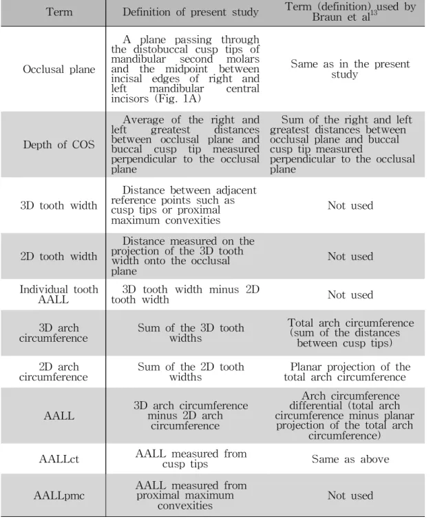
Term Definitionofpresentstudy Term (definition)usedby Braunetal13
Occlusalplane
A plane passing through the distobuccalcusp tips of mandibular second molars and the midpoint between incisal edges of right and left mandibular central incisors(Fig.1A)
Sameasinthepresent study
DepthofCOS
Average ofthe rightand left greatest distances between occlusalplane and buccal cusp tip measured perpendicularto theocclusal plane
Sum oftherightandleft greatestdistancesbetween occlusalplaneandbuccal cusptipmeasured
perpendiculartotheocclusal plane
3D toothwidth
Distancebetweenadjacent referencepointssuchas cusptipsorproximal maximum convexities
Notused
2D toothwidth
Distancemeasuredonthe projectionofthe3D tooth widthontotheocclusal plane
Notused
Individualtooth
AALL 3D tooth width minus 2D
toothwidth Notused
3D arch
circumference Sum ofthe3D tooth widths
Totalarchcircumference (sum ofthedistances
betweencusptips) 2D arch
circumference Sum ofthe2D tooth
widths Planarprojectionofthe totalarchcircumference
AALL 3D archcircumference minus2D arch
circumference
Archcircumference differential(totalarch circumferenceminusplanar projectionofthetotalarch
circumference) AALLct AALL measuredfrom
cusptips Sameasabove
AALLpmc AALL measuredfrom proximalmaximum
convexities Notused
Tabl es
Table1.Definitionsofthetermsusedinthepresentstudy.
- 15 -
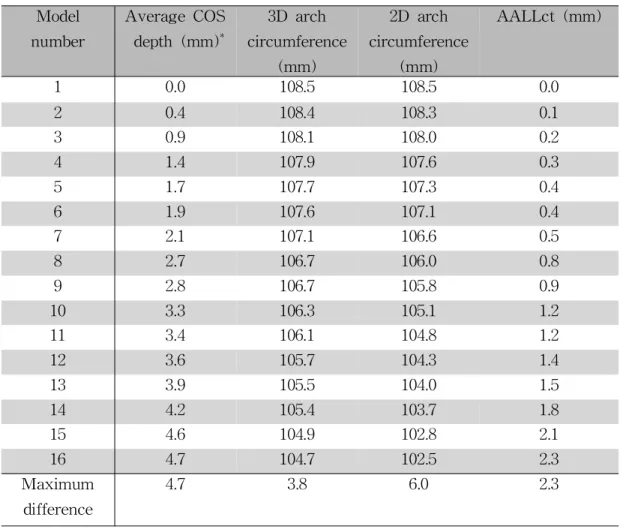
Table2. ChangesinarchcircumferencesandAALL accordingtoincreasesinthe COS depthusingthecusptipsasreferencepoints.
Model number
AverageCOS depth(mm)*
3D arch circumference
(mm)
2D arch circumference
(mm)
AALLct(mm)
1 0.0 108.5 108.5 0.0
2 0.4 108.4 108.3 0.1
3 0.9 108.1 108.0 0.2
4 1.4 107.9 107.6 0.3
5 1.7 107.7 107.3 0.4
6 1.9 107.6 107.1 0.4
7 2.1 107.1 106.6 0.5
8 2.7 106.7 106.0 0.8
9 2.8 106.7 105.8 0.9
10 3.3 106.3 105.1 1.2 11 3.4 106.1 104.8 1.2 12 3.6 105.7 104.3 1.4 13 3.9 105.5 104.0 1.5 14 4.2 105.4 103.7 1.8 15 4.6 104.9 102.8 2.1 16 4.7 104.7 102.5 2.3 Maximum
difference
4.7 3.8 6.0 2.3
*Averageofright-andleft-sideCOS depths
**AALL :theamountofadditionalarchlengthrequiredforlevelingtheCOS
- 16 -
Table 3.Changes in arch circumferences and AALL according to increases in COS depthusingtheproximalmaximum convexitiesasreferencepoints.
Model number
AverageCOS depth(mm)*
3D arch circumference
(mm)
2D arch circumference
(mm)
AALLpmc (mm)
1 0.0 112.7 112.5 0.2
2 0.4 112.7 112.5 0.2
3 0.9 112.6 112.4 0.2
4 1.4 112.6 112.3 0.4
5 1.7 112.6 112.1 0.4
6 1.9 112.6 112.1 0.6
7 2.1 112.6 111.9 0.6
8 2.7 112.4 111.5 0.9
9 2.8 112.4 111.4 1.0
10 3.3 112.4 111.0 1.3 11 3.4 112.3 110.9 1.4 12 3.6 112.4 110.7 1.7 13 3.9 112.5 110.3 2.2 14 4.2 112.5 110.1 2.4 15 4.6 112.3 109.5 2.8 16 4.7 112.3 109.1 3.2 Maximum
difference
4.7 0.4 3.4 3.0
*Averageofright-andleft-sideCOS depths
**AALL :theamountofadditionalarchlengthrequiredforlevelingtheCOS
- 17 -
Fi gur es
Figure1.A,Theocclusalplanewasdeterminedusing thedistobuccalcusptips ofthe mandibularsecond molars and the midpointbetween the incisaledges of themandibularrightandleftcentralincisors.ThedepthoftheCOS (indicatedby double-headedarrows)wasdeterminedbycalculatingtheaverageoftherightand leftmaximum distancesbetween thedeepestcusp tipsand theocclusalplane;B, During each setup,even marginalridge relationships were maintained to form curved-ribbon-shaped,continuousocclusalsurfaces.
- 18 -
Figure2A. Figure2B.
Figure2.Using a clipping tool,theinterproximalcontactareaswerevisualized and adjusted to minimize overlapping of the interproximal surfaces of the adjacent teeth.A,The arrow indicates the point contact made between the lowerrightfirstand second molars;B,The intercanine and intermolarwidths (indicated by double-headed arrows)were maintained constant(at27 and 46 mm,respectively)ineachsetup.
- 19 -
Figure3A. Figure3B.
Figure3.The3D arch circumferenceiscalculated asthesum ofthe3D tooth widths,corresponding tothedistancesbetweenadjacentreferencepoints,shown asorangedotsinA andB.A,3D toothwidthsmeasuredusing thecusptipas a reference; B, 3D tooth widths measured using the proximal maximum convexityasareference.
- 20 -
Figure4A. Figure4B.
Figure 4.The2D arch circumference iscalculated asthesum ofthe2D tooth widths,whicharetheprojectionsofthe3D toothwidthsontotheocclusalplane. A,2D tooth widths measured using the cusp tip as a reference;B,2D tooth widthsmeasuredusingtheproximalmaximum convexityasareference.
- 21 -
Figure5.Changesin3D and2D archcircumferencesaccordingtotheuseof cusptipsandproximalmaximum convexitiesasreferences.The3D arch
circumferencedecreasedby3.8mm inthecusp-tipmeasurementsandby0.4mm intheproximalconvexitymeasurementsasCOS increasedfrom 0to4.7mm.The gapbetweenthe3D archcircumferenceandthe2D archcircumferenceisthe AALL.DataaremeanandSD values.
- 22 -
Figure6.Measurementsof3D toothwidth minus2D tooth widthforeachtooth.
Inthecusp-tipmeasurements,thewidthsweremeasuredbetweenthecusptipsof theadjacentteeth,whilein theproximalmaximum-convexity measurementsthey weremeasured between themesialanddistalmaximum convexities.Mean values of16setupmodelsareshown.
- 23 -
Figure7A. Figure7B.
Figure 7. Scatter diagram of AALL versus COS depth. A, AALLct; B, AALLpmc.
- 24 -
Figure8.ComparisonofestimationsofAALL invariousstudies.