저작자표시-비영리-변경금지 2.0 대한민국 이용자는 아래의 조건을 따르는 경우에 한하여 자유롭게
l 이 저작물을 복제, 배포, 전송, 전시, 공연 및 방송할 수 있습니다. 다음과 같은 조건을 따라야 합니다:
l 귀하는, 이 저작물의 재이용이나 배포의 경우, 이 저작물에 적용된 이용허락조건 을 명확하게 나타내어야 합니다.
l 저작권자로부터 별도의 허가를 받으면 이러한 조건들은 적용되지 않습니다.
저작권법에 따른 이용자의 권리는 위의 내용에 의하여 영향을 받지 않습니다. 이것은 이용허락규약(Legal Code)을 이해하기 쉽게 요약한 것입니다.
Disclaimer
저작자표시. 귀하는 원저작자를 표시하여야 합니다.
비영리. 귀하는 이 저작물을 영리 목적으로 이용할 수 없습니다.
변경금지. 귀하는 이 저작물을 개작, 변형 또는 가공할 수 없습니다.
MS. THESIS
Secrecy Performance of Full-Duplex Relay System With Randomly Located
Eavesdroppers
무작위로 위치한 다수 도청자가 존재하는 전이중 중계 시스템의 보안 성능
BY
Donghyun Jung
AUGUST 2017
DEPARTMENT OF ELECTRICAL AND COMPUTER ENGINEERING
COLLEGE OF ENGINEERING
Abstract
Secrecy Performance of Full-Duplex Relay System With Randomly Located
Eavesdroppers
Donghyun Jung Department of Electrical and Computer Engineering The Graduate School Seoul National University
Full-duplex (FD) operation improves the spectral efficiency of a relay system where the relay simultaneously transmits and receives signals on the same channel. The performance of FD relay systems is limited by self-interference, i.e., signal leakage from the relay’s transmit antenna to its receive antenna.
However, in the FD relay system with malicious eavesdroppers, simultaneous transmission from the source and relay confuses the eavesdroppers.
In this thesis, we investigate a FD relay system where a source commu- nicates with a destination via a decode-and-forward relay in the presence of randomly located eavesdroppers. We derive analytical expressions for the secrecy outage probability and the average secrecy rate of the system. Sim- ulation results show that the secrecy performance of the system is improved as the density of eavesdroppers decreases. It is also shown that the FD re- lay system has higher secrecy performance than the half-duplex relay system when a large portion of self-interference is cancelled.
Keywords: Physical layer security, stochastic geometry, full-duplex relay system, randomly located eavesdroppers, secrecy outage probability, average secrecy rate.
Student Number: 2015-20987.
Contents
Abstract i
Contents iii
List of Figures iv
Chapter 1 Introduction 1
Chapter 2 System Model 5
Chapter 3 Secrecy Performance Analysis 11
3.1 SINR Distribution . . . 12 3.2 Secrecy Outage Probability . . . 17 3.3 Average Secrecy Rate . . . 20
Chapter 4 Simulation Results 22
Chapter 5 Conclusion 38
List of Figures
Figure 4.1 Secrecy outage probability versus density of eavesdrop- persλewith various values of self-interference cancellation fac- tor ρ. . . 27 Figure 4.2 Secrecy outage probability versus self-interference can-
cellation factor ρ with various values of density of eavesdrop- pers λe. . . 28 Figure 4.3 Secrecy outage probability versus transmit SNR P/N0
with various values of density of eavesdroppers λe. . . 30 Figure 4.4 Secrecy outage probability versus transmit SNR P/N0
with various values of self-interference cancellation factor ρ. . . 31 Figure 4.5 Average secrecy rate versus density of eavesdroppers
λe with various values of self-interference cancellation factor ρ. 33
Figure 4.6 Average secrecy rate versus self-interference cancella- tion factor ρ with various values of density of eavesdroppers λe. . . 34 Figure 4.7 Average secrecy rate versus transmit SNR P/N0 with
various values of density of eavesdroppers λe. . . 36 Figure 4.8 Average secrecy rate versus transmit SNR P/N0 with
various values of self-interference cancellation factor ρ. . . 37
Chapter 1
Introduction
Full-duplex (FD) operation improves the spectral efficiency of a relay system where the relay simultaneously transmits and receives signals on the same channel [1]. However, the main limitation of the FD relay system is that simultaneous transmission and reception at the relay causes a high level of self-interference, i.e., signal leakage from the relay’s transmit antenna to its receive antenna. Several techniques to mitigate the effect of the self- interference at FD nodes have been investigated, such as passive cancellation, analog cancellation, and digital cancellation [2]-[5].
Communication is secure when a legitimate receiver successfully decodes its received signal from a transmitter while an eavesdropper cannot overhear the signal. Physical layer security guarantees the secure communication by using the characteristics of wireless channels without encryption methods [6], [7]. The effects of malicious eavesdroppers who attempt to overhear the communication between the legitimate transmitter and receiver have been considered.
Randomly located eavesdroppers have been recently investigated where eavesdroppers’ positions are modeled by using stochastic geometry [8]-[13].
In [8], secrecy performance of a downlink cellular system was analyzed where a multi-antenna base station communicates with multiple malicious users in the presence of external eavesdroppers. In [9], an artificial noise-aided multi- antenna transmission scheme was studied where optimal power allocation between an information signal and an artificial noise which minimizes the secrecy outage probability was obtained. In [10], secrecy performance of a downlink cellular system in the presence of randomly located eavesdroppers was analyzed where a multi-antenna base station employs transmit antenna
selection to enhance the secrecy performance. In [11], a secure transmission scheme in a half-duplex (HD) relay system was investigated where the source and relay transmit artificial noises along with information signals to confuse eavesdroppers.
In a FD relay system with an eavesdropper, simultaneous transmission from the source and relay confuses the eavesdropper [14]-[17]. In [14], a FD jamming relay system was proposed where the relay receives an information signal from the source and simultaneously transmits a jamming signal to the eavesdropper. In [15], a power allocation algorithm which maximizes the secrecy rate of the FD relay system was presented. In [16], the secrecy outage probability of a two-way FD relay system with optimal relay seletion was analyzed. In [17], an Almouti-based beamforming and artificial noise design was proposed to maximize the secrecy rate of the two-way FD relay system.
However, most previous works focused on eavesdropper(s) at deterministic position(s) in the FD relay system.
In this thesis, we consider a FD relay system with randomly located eaves- droppers. We derive analytical expressions for the secrecy outage probability
and the average secrecy rate of the system. Computer simulations verify the validity of our analysis. Also, the performance of a HD relay system with randomly located eavesdroppers is compared with the FD relay system.
The rest of this thesis is organized as follows. In chapter 2, the system model is described. In chapter 3, the secrecy outage probability and the aver- age secrecy rate are analyzed. In chapter 4, simulation results are provided.
Finally, conclusions are drawn in chapter 5.
Chapter 2
System Model
Consider a FD relay system where a source s communicates with a desti- nation d via a decode-and-forward (DF) relay r in the presence of multiple eavesdroppers. Assume that the source, the relay, and the destination are located at fixed positions and there is no direct link between the source and the destination. Assume that the eavesdroppers are located according to a homogeneous Poisson point process (PPP) Φe with density λe. Suppose that the FD relay has two antennas, one for transmission and one for recep- tion while the source, the destination, and the eavesdroppers have a single
antenna.
Suppose that transmission takes place in blocks. In each block, the source transmits a signal to the relay and, at the same time, the relay transmits a signal to the destination. The relay receives not only the signal transmitted from the source but also the signal transmitted from itself which becomes interference. The relay decodes and re-encodes the received signal, and in the next block, transmits the re-encoded signal to the destination.
The eavesdroppers attempt to overhear the signals transmitted from the source and the relay. Suppose that the source and the relay use different codebooks, so that the eavesdroppers can only individually decode the re- ceived signal from the first hop and that from the second hop [11]. Assume that the eavesdroppers are non-colluding, i.e., each eavesdropper does not cooperate with other eavesdroppers [9].
Assume that all channels remain constant over a block and vary inde- pendently from one block to another. Assume that the coefficient of the channel from node i to node j in block k, hij[k], i, j ∈ {s, r, d, e}, e ∈Φe, is an independent complex Gaussian random variable with zero mean and unit
variance. Assume that the channels have an additive white Gaussian noise (AWGN) with zero mean and variance N0.
In block k, the source transmits a signal xs[k] with power Ps to the relay and the relay transmits the re-encoded signal of xs[k −1], denoted by ˆxs[k −1], with power Pr to the destination. Let ρ, ρ ∈ [0,1], denote the self-interference cancellation factor which represents a residual portion of self-interference power at the relay after cancellation [5]. The received signal at the relay is given by
yr[k] =√
d−srαhsr[k]xs[k] +√
ρhrr[k]ˆxs[k−1] +nr[k] (2.1)
where dsr is the distance from the source to the relay, α is the path-loss exponent, andnr[k] is an AWGN. The received signal at an eavesdropper (at position)e, e∈Φe, is given by
ye[k] =√
d−seαhse[k]xs[k] +√
d−reαhre[k]ˆxs[k−1] +ne[k] (2.2)
wheredseand dre are the distance from the eavesdroppere to the source and
that to the relay, respectively, and ne[k] is an AWGN.
In block k+ 1, the received signal at the destination is given by
yd[k+ 1] =
√
d−rdαhrd[k+ 1]ˆxs[k] +nd[k+ 1] (2.3)
where drd is the distance from the relay to the destination and nd[k+ 1] is an AWGN. The received signal at the eavesdropper e is given by
ye[k+ 1] =√
d−reαhre[k+ 1]ˆxs[k]
+√
d−seαhse[k+ 1]xs[k+ 1] +ne[k+ 1]. (2.4)
The signal-to-interference-plus-noise ratios (SINR) at the relay is given by
γsr = Psd−srα|hsr[k]|2
ρPr|hrr[k]|2+N0. (2.5) The signal-to-noise ratio (SNR) at the destination is given by
γrd = Prd−rdα|hrd[k+ 1]|2
N0 . (2.6)
For DF relaying, the end-to-end SINR from the source to the destination is given by
γd= min{γsr, γrd}. (2.7)
The SINR at the eavesdropperefor the signal transmitted from the source is given by
γse= Psd−seα|hse[k]|2
Prd−reα|hre[k]|2+N0. (2.8) The SINR at the eavesdroppere for the signal transmitted from the relay is given by
γre = Prd−reα|hre[k+ 1]|2 Psd−seα|hse[k+ 1]|2+N0
. (2.9)
Since the source and relay use different codebooks, the SINR at the eaves- droppere is given by [11]
γe= max{γse, γre}. (2.10)
For non-colluding eavesdroppers, the secrecy rate of the system is determined by the most detrimental eavesdropper, i.e., an eavesdropper with the highest
SINR which is given by
γe∗ = max
e∈Φe
γe. (2.11)
Chapter 3
Secrecy Performance Analysis
In this chapter, we first analyze the cumulative distribution functions (CDFs) of γd and γe∗. Then, we derive analytical expressions for the secrecy outage probability and the average secrecy rate of the FD relay system.
3.1 SINR Distribution
The CDF of the end-to-end SINR from the source to the destination is given by
Fγd(x) = Pr[γd< x]
=1−Pr[min{γsr, γrd} ≥x]
=1−Pr[γsr≥x, γrd ≥x]
=1−(1−Fγsr(x)) (1−Fγrd(x)) (3.1)
where Fγsr(x) and Fγrd(x) are the CDFs of γsr and γrd, respectively. The CDF of the SINR at the relay is given by
Fγsr(x) = Pr[γsr < x]
= Pr
[ Psd−srαU ρPrV +N0 < x
]
= Pr [
U < ρPrV +N0
Psd−srα x ]
=
∫ ∞
0
∫ ρPr v+N0
Psd−α sr
x 0
fU,V(u, v)dudv (3.2)
whereU =|hsr[k]|2,V =|hrr[k]|2, andfU,V(u, v) is the joint probability den- sity function (PDF) ofU andV. Since U andV are independent exponential random variables with unit mean, we have
Fγsr(x) =
∫ ∞
0
∫ ρPr v+N0
Psd−α sr
x 0
fU(u)fV(v)dudv
=
∫ ∞
0
exp(−v)
∫ ρPr v+N0
Psd−α sr
x 0
exp(−u)dudv
=
∫ ∞
0
exp(−v) (
1−exp (
−ρPrv+N0 Psd−srα x
)) dv
=1−exp (
−N0dαsr Ps x
) ∫ ∞
0
exp (
− (
1 + ρPrdαsr Ps x
) v
) dv
=1−exp (
−N0dαsr Ps
x ) (
1 + ρPrdαsr Ps
x )−1
(3.3)
wherefU(u) and fV(v) are the PDFs of U and V, respectively. The CDF of the SNR at the destination is given by
Fγrd(x) = Pr[γrd< x]
= Pr [
|hrd[k+ 1]|2 < N0dαrd Pr x
]
=1−exp (
−N0dαrd Pr x
)
(3.4)
where |hrd[k + 1]|2 has an exponential distribution with unit mean. From (3.1), (3.3), and (3.4), the CDF of the end-to-end SINR from the source to the destination is obtained as
Fγd(x) = 1−exp (
−N0 (dαsr
Ps
+dαrd Pr
) x
)(
1 + ρPrdαsr Ps
x )−1
. (3.5)
The CDF of the SINR at the most detrimental eavesdropper is given by
Fγe∗(x) = Pr[γe∗ < x]
=EΦe
[∏
e∈Φe
Pr[max{γse, γre}< x]
]
=EΦe
[∏
∈
Pr[γse< x] Pr[γre < x]
]
=EΦe
[∏
e∈Φe
Fγse(x)Fγre(x) ]
(3.6)
whereFγse(x) andFγre(x) are the CDFs ofγseandγre, respectively. Similarly to the derivation of (3.3), the CDF of the SINR at the eavesdropper e for the signal transmitted from the source is given by
Fγse(x) = 1−exp (
−N0dαse Ps
x ) (
1 + Pr Ps
(dse dre
)α
x )−1
(3.7)
and the CDF of the SINR at the eavesdropper e for the signal transmitted from the relay is given by
Fγre(x) = 1−exp (
−N0dαre Pr x
) ( 1 + Ps
Pr (dre
dse )α
x )−1
. (3.8)
From (3.6), (3.7), and (3.8), the CDF of the SINR at the most detrimental eavesdropper is obtained as
Fγe(x) =EΦe [∏
e∈Ke
(
1−exp (
−N0dαse Ps x
) ( 1 + Pr
Ps (dse
dre )α
x )−1)
× (
1−exp (
−N0dαre Pr x
) ( 1 + Ps
Pr (dre
dse )α
x
)−1)]
(a)= exp (
−λe
∫ ∞
0
∫ 2π
0
dse {
exp (
−N0dαse Ps x
) ( 1 + Pr
Ps (dse
dre )α
x )−1
+ exp (
−N0dαre Pr x
) ( 1 + Ps
Pr (dre
dse )α
x )−1
−exp (
−N0 (dαse
Ps + dαre Pr
) x
) ( 1 + Pr
Ps (dse
dre )α
x )−1
× (
1 + Ps Pr
(dre dse
)α
x )−1}
dθddse
(b)= exp (
−λe
∫ ∞
0
∫ 2π 0
dse
{ exp
(
−N0dαse Ps x
)
× (
1 + Pr Ps
(
dse
√d2sr+d2se−2dsrdsecosθ )α
x )−1
+ exp (
−N0√
d2sr+d2se−2dsrdsecosθα
Pr x
)
× (
1 + Ps Pr
(√d2sr+d2se−2dsrdsecosθ dse
)α
x )−1
−exp (
−N0 {
dαse Ps +
√d2sr+d2se−2dsrdsecosθα Pr
} x
)
× (
1 + Pr Ps
(
dse
√d2sr+d2se−2dsrdsecosθ )α
x )−1
× (
1 + Ps
Pr
(√d2sr+d2se−2dsrdsecosθ dse
)α
x )−1
dθddse
(3.9)
where (a) follows by using the probability generating functional of the PPP Φe which is given by [18]
EΦe
[∏
x∈Φe
f(x) ]
= exp (
−λe
∫
R2
(1−f(x))dx )
(3.10)
and by changing to the polar coordinates, and (b) follows from the law of cosines, i.e.,dre =√
d2sr+d2se−2dsrdsecosθ.
3.2 Secrecy Outage Probability
The secrecy rate of the system is given by
R = [log(1 +γd)−log(1 +γe∗)]+ (3.11)
where [x]+ ∆= max{0, x}. The secrecy outage probability of the system is given by [12]
Pout = Pr[R≤0]
= Pr[log(1 +γd)−log(1 +γe∗)≤0]
= Pr[γd≤γe∗]
=
∫ ∞
0
∫ ∞
x
fγd(x)fγe∗(y)dydx
=1−
∫ ∞
0
fγd(x)Fγe∗(x)dx (3.12)
wherefγd(x) andfγe∗(y) are the PDFs ofγd and γe∗, respectively. The PDF of the end-to-end SINR from the source to the destination is given by
fγd(x) =dFγd(x) dx
=− d dx
{ exp
(
−N0 (dαsr
Ps +dαrd Pr
) x
) (
1 + ρPrdαsr Ps x
)−1}
= exp (
−N0 (dαsr
Ps +dαrd Pr
) x
) (
1 + ρPrdαsr Ps x
)−1
× (
N0
(dαsr Ps +dαrd
Pr )
+ ( Ps
ρPrdαsr +x )−1)
. (3.13)
From (3.9), (3.12), and (3.13), the secrecy outage probability is obtained as
Pout =1−
∫ ∞
0
(
1 + ρPrdαsr Ps x
)−1( N0
(dαsr Ps +dαrd
Pr )
+ (
x+ Ps ρPrdsr
)−1)
×exp (
−N (dαsr
Ps +dαrd Pr
)
x−λe
∫ ∞
0
∫ 2π 0
dse {
exp (
−N0dαse Ps x
)
× (
1 + Pr Ps
(
dse
√d2sr+d2se−2dsrdsecosθ )α
x )−1
+ exp (
−N0
√d2sr+d2se−2dsrdsecosθα Pr
x )
× (
1 + Ps Pr
(√d2sr+d2se−2dsrdsecosθ dse
)α
x )−1
−exp (
−N0 (
dαse Ps +
√d2sr+d2se−2dsrdsecosθα Pr
) x
)
× (
1 + Pr Ps
(
dse
√d2sr+d2se−2dsrdsecosθ )α
x )−1
× (
1 + Ps Pr
(√d2sr+d2se−2dsrdsecosθ dse
)α
x )−1
dθddse
dx.
(3.14)
3.3 Average Secrecy Rate
The average secrecy rate of the system is given by [19]
Ravg =E[R]
= 1 ln 2
∫ ∞
0
Fγe∗(x)
1 +x (1−Fγd(x))dx. (3.15)
From (3.5), (3.9), and (3.15), the average secrecy rate is obtained as
Ravg = 1 ln 2
∫ ∞
0
(1 +x)−1 (
1 + ρPrdsr Ps
x )−1
×exp (
−N0
(dαsr Ps +dαrd
Pr )
x−λe
∫ ∞
0
∫ 2π 0
dse
{ exp
(
−N0dαse Ps x
)
× (
1 + Pr Ps
(
dse
√d2sr+d2se−2dsrdsecosθ )α
x )−1
+ exp (
−N0√
d2sr+d2se−2dsrdsecosθα
Pr x
)
× (
1 + Ps Pr
(√d2sr+d2se−2dsrdsecosθ dse
)α
x )−1
−exp (
−N0 (
dαse Ps +
√d2sr+d2se−2dsrdsecosθα Pr
) x
)
× (
1 + Pr P
(
dse
√d2 +d2 −2d d cosθ )α
x )−1
× (
1 + Ps Pr
(√d2sr+d2se−2dsrdsecosθ dse
)α
x )−1
dθddse
dx.
(3.16)
Closed-form expressions of (3.14) and (3.16) are difficult to obtain, but they can be computed by using Gaussian quadrature method or software such as Mathematica [11]-[13].
Chapter 4
Simulation Results
Consider a FD relay system which consists of a source, a DF relay, a des- tination, and multiple eavesdroppers. Suppose that the path-loss exponent α = 4, the distances from the source to the relay and from the relay to the destinationdsr=drd = 10 m, and the transmit SNRs of the source and relay Ps/N0 =Pr/N0 =P/N0. In figures 4.1, 4.2, 4.5, and 4.6, the performance of a HD relay system is also depicted for comparison [20].
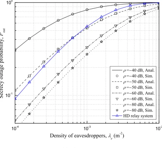
Figure 4.1 shows the secrecy outage probability of the relay systems versus
the density of eavesdroppersλe with various values of self-interference cancel- lation factorρ for the transmit SNR P/N0 = 50,60 dB. It is shown that the analytical results perfectly match the simulation results. It is shown that as λe increases, the secrecy outage probability of the relay systems increases. It is also shown that the FD relay system has lower secrecy outage probability than the HD relay system for ρ = −80,−60,−50 dB when P/N0 = 50 dB and for ρ=−80,−60 dB when P/N0 = 60 dB.
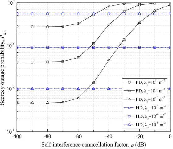
Figure 4.2 shows the secrecy outage probability of the relay systems versus the self-interference cancellation factor ρ with various values of the density of eavesdroppersλe for the transmit SNRP/N0 = 60 dB. It is shown that as ρincreases, the secrecy outage probability of the FD relay system increases.
It is shown that the FD relay system has lower secrecy outage probability than the HD relay system for small values ofρ.
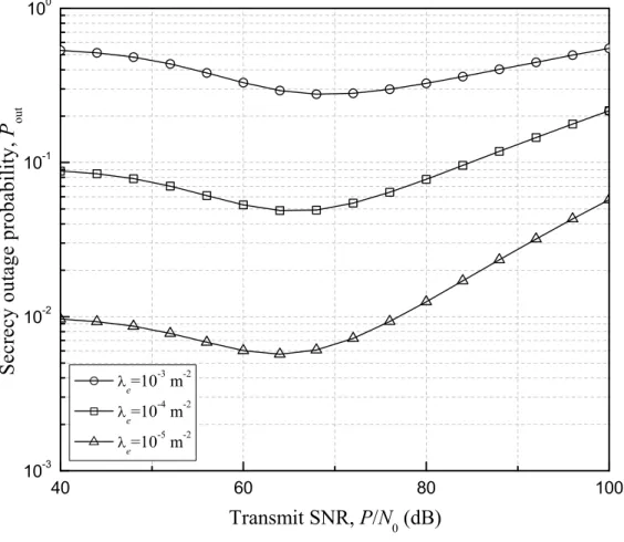
Figure 4.3 shows the secrecy outage probability of the FD relay system versus the transmit SNR P/N0 with various values of the density of eaves- droppers λe for the self-interference cancellation factor ρ=−80,−60 dB. It is shown that as P/N0 increases, the secrecy outage probability of the FD
relay system decreases until it reaches a minimum, and then increases. It is shown that as λe decreases, the optimal value ofP/N0 which minimizes the secrecy outage probability of the FD relay system decreases.
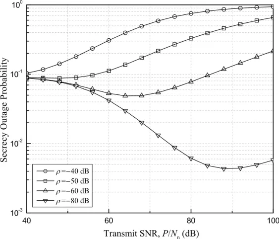
Figure 4.4 shows the secrecy outage probability of the FD relay system versus the transmit SNR P/N0 with various values of the self-interference cancellation factor ρ for the density of eavesdroppers λe = 10−4 m−2. It is shown that as ρ decreases, the optimal value of P/N0 which minimizes the secrecy outage probability of the FD relay system increases.
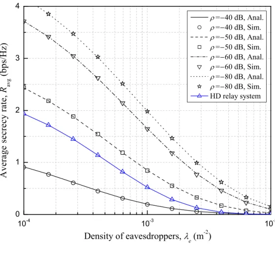
Figure 4.5 shows the average secrecy rate of the relay systems versus the density of eavesdroppersλe with various values of self-interference cancella- tion factor ρ for the transmit SNR P/N0 = 50,60 dB. It is shown that the analytical results perfectly match the simulation results. It is shown that as λe increases, the average secrecy rate of the relay systems decreases. It is shown that the FD relay system has higher average secrecy rate than the HD relay system for ρ=−80,−60,−50 dB.
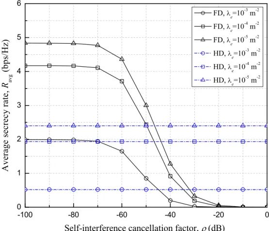
Figure 4.6 shows the average secrecy rate of the relay systems versus the self-interference cancellation factor ρ with various values of density of
eavesdroppers λe for the transmit SNR P/N0 = 60 dB. It is shown that as ρ increases, the average secrecy rate of the FD relay system decreases. It is shown that the FD relay system has higher average secrecy rate than the HD relay system for small values of ρ.
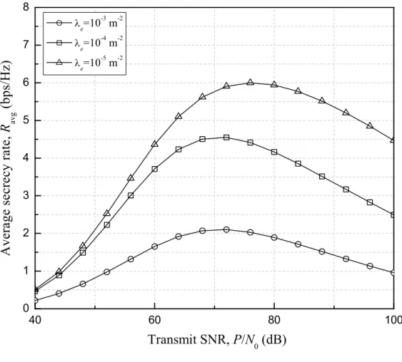
Figure 4.7 shows the average secrecy rate of the FD relay system versus the transmit SNR P/N0 with various values of density of eavesdroppers λe for the self-interference cancellation factorρ=−80,−60 dB. It is shown that asP/N0 increases, the average secrecy rate of the FD relay system increases until it reaches a maximum, and then decreases.
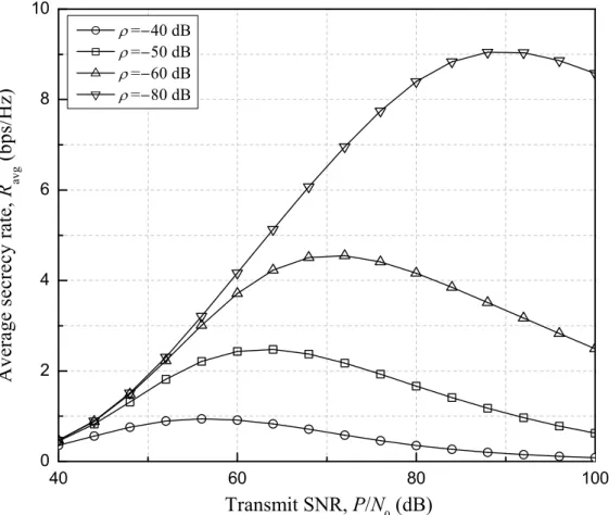
Figure 4.8 shows the average secrecy rate of the FD relay system versus the transmit SNR P/N0 with various values of the self-interference cancel- lation factor ρ for the density of eavesdroppers λe = 10−4 m−2. It is shown that asρ decreases, the optimal value of P/N0 which minimizes the average secrecy rate of the FD relay system increases.
10 -4
10 -3
10 -2 10
-1 10
0
Density of eavesdroppers, e
(m -2
)
= 40 dB, Anal.
= 40 dB, Sim.
= 50 dB, Anal.
= 50 dB, Sim.
= 60 dB, Anal.
= 60 dB, Sim.
= 80 dB, Anal.
= 80 dB, Sim.
HD relay system Secrecyoutageprobability,P out
(a)P/N0= 50 dB
10 -4
10 -3
10 -2 10
-1 10
0
Density of eavesdroppers, e
(m -2
)
= 40 dB, Anal.
= 40 dB, Sim.
= 50 dB, Anal.
= 50 dB, Sim.
= 60 dB, Anal.
= 60 dB, Sim.
= 80 dB, Anal.
= 80 dB, Sim.
HD relay system Secrecyoutageprobability,P out
(b)P/N0= 60 dB
Figure 4.1. Secrecy outage probability versus density of eavesdroppers λe
with various values of self-interference cancellation factorρ.
-100 -80 -60 -40 -20 0 10
-3 10
-2 10
-1 10
0
FD, e
=10 -3
m -2
FD, e
=10 -4
m -2
FD, e
=10 -5
m -2
HD, e
=10 -3
m -2
HD, e
=10 -4
m -2
HD, e
=10 -5
m -2
Self-interference canncellation factor, (dB) Secrecyoutageprobability,P out
Figure 4.2. Secrecy outage probability versus self-interference cancellation factor ρ with various values of density of eavesdroppers λe.
40 60 80 100 10
-4 10
-3 10
-2 10
-1 10
0
e
=10 -3
m -2
e
=10 -4
m -2
e
=10 -5
m -2 Secrecyoutageprobability,P out
Transmit SNR, P/N 0
(dB)
(a)ρ=−80 dB
40 60 80 100 10
-3 10
-2 10
-1 10
0
e
=10 -3
m -2
e
=10 -4
m -2
e
=10 -5
m -2 Secrecyoutageprobability,P out
Transmit SNR, P/N 0
(dB)
(b)ρ=−60 dB
Figure 4.3. Secrecy outage probability versus transmit SNR P/N0 with var- ious values of density of eavesdroppersλe.
40 60 80 100 10
-3 10
-2 10
-1 10
0
Transmit SNR, P/N 0
(dB)
= 40 dB
= 50 dB
= 60 dB
= 80 dB
SecrecyOutageProbability
Figure 4.4. Secrecy outage probability versus transmit SNR P/N0 with var- ious values of self-interference cancellation factorρ.
10 -4
10 -3
10 -2 0.0
0.5 1.0 1.5 2.0
= 40 dB, Anal.
= 40 dB, Sim.
= 50 dB, Anal.
= 50 dB, Sim.
= 60 dB, Anal.
= 60 dB, Sim.
= 80 dB, Anal.
= 80 dB, Sim.
HD relay system
Averagesecrecyrate,R avg
(bps/Hz)
Density of eavesdroppers, e
(m -2
)
(a)P/N0= 50 dB
10 -4
10 -3
10 -2 0
1 2 3 4
= 40 dB, Anal.
= 40 dB, Sim.
= 50 dB, Anal.
= 50 dB, Sim.
= 60 dB, Anal.
= 60 dB, Sim.
= 80 dB, Anal.
= 80 dB, Sim.
HD relay system
Averagesecrecyrate,R avg
(bps/Hz)
Density of eavesdroppers,
e (m
-2
)
(b)P/N0= 60 dB
Figure 4.5. Average secrecy rate versus density of eavesdroppers λe with various values of self-interference cancellation factorρ.
-100 -80 -60 -40 -20 0 0
1 2 3 4 5 6
FD, e
=10 -3
m -2
FD, e
=10 -4
m -2
FD, e
=10 -5
m -2
HD, e
=10 -3
m -2
HD, e
=10 -4
m -2
HD, e
=10 -5
m -2
Averagesecrecyrate,R avg
(bps/Hz)
Self-interference cancellation factor, (dB)
Figure 4.6. Average secrecy rate versus self-interference cancellation factor ρwith various values of density of eavesdroppers λe.
40 60 80 100 0
2 4 6 8 10 12
Transmit SNR, P/N 0
(dB) e
=10 -3
m -2
e
=10 -4
m -2
e
=10 -5
m -2
Averagesecrecyrate,R avg
(bps/Hz)
(a)ρ=−80 dB
40 60 80 100 0
1 2 3 4 5 6 7 8
e
=10 -3
m -2
e
=10 -4
m -2
e
=10 -5
m -2
Transmit SNR, P/N 0
(dB) Averagesecrecyrate,R avg
(bps/Hz)
(b)ρ=−60 dB
Figure 4.7. Average secrecy rate versus transmit SNR P/N0 with various values of density of eavesdroppers λe.
40 60 80 100 0
2 4 6 8 10
= 40 dB
= 50 dB
= 60 dB
= 80 dB
Transmit SNR, P/N 0
(dB) Averagesecrecyrate,R avg
(bps/Hz)
Figure 4.8. Average secrecy rate versus transmit SNR P/N0 with various values of self-interference cancellation factorρ.
Chapter 5
Conclusion
In this thesis, we consider a full-duplex (FD) relay system in the presence of randomly located eavesdroppers. We analyze the cumulative density func- tions of the end-to-end signal-to-interference-plus-noise ratio (SINR) from the source to the destination and the SINR at the most detrimental eaves- dropper. We derive analytical expressions for the secrecy outage probability and the average secrecy rate of the system. Simulation results perfectly match the analytical results of the secrecy outage probability and the aver- age secrecy rate. It is shown that the secrecy performance of the system is