Original Article
원고 접수일 2011년 9월 5일, 원고 수정일 2011년 10월 11일, 게재 확정일 2011년 11월 22일
책임저자 오승환
(570-711) 전북 익산시 신용동 344-2, 원광대학교 치과대학병원 구강악안면외과 Tel: 063-859-2921, Fax: 063-857-4002, E-mail: [email protected]
RECEIVED September 5, 2011, REVISED October 11, 2011, ACCEPTED November 22, 2011
Correspondence to Sung-Hwan Oh
Department Oral and Maxillofacial Surgery, Dental Hospital, Wonkwang University
344-2, Sinyong-dong, Iksan 570-711, Korea
Tel: 82-63-859-2921, Fax: 82-63-857-4002, E-mail: omsosh@wonkwang.
ac.kr
CC This is an open access article distributed under the terms of the Creative Commons Attribution Non-Commercial License (http://creativecommons.org/licenses/
by-nc/3.0) which permits unrestricted non-commercial use, distribution, and reproduction in any medium, provided the original work is properly cited.
안면 비대칭 환자에서 Cone Beam Computed Tomography를 이용한 하악골 해부학적 변이의 분석
박성원ㆍ오승환ㆍ이재인1
원광대학교 치과대학 구강악안면외과학교실, 1치과보철학교실
Abstract
Cone Beam Computed Tomography Analysis of Mandibular Anatomical Variation in a Patient with Facial Asymmetry
Seong-Won Park, Sung-Hwan Oh, Jae In Lee
1Departments Oral and Maxillofacial Surgery,
1Prosthodontics, College of Dentistry, Wonkwang University
Purpose: The study was performed to compare patients with anatomical variations in facial asymmetry with patients in the normal range using cone-beam computed tomography (CBCT) and to take the preoperative condition into consideration in the case of a sagittal split ramus osteotomy (SSRO).
Methods: The study was conducted on 46 adult patients composed of 2 subdivided groups, an asymmetry group (n=26) and a symmetry group (n=20). The asymmetry group was divided between patients with hemimandibular hyperplasia (HH, n=8) and hemimandibular elongation (HE, n=18). Using cross-sectional computed tomography images, the thickness of cancell- eous bone in the buccal area of the mandible, thickness of buccal cortex in the buccal aspect of the mandible, thickness of cancellous bone in the inferior aspect of the mandible, thickness of buccal cortex in the inferior aspect of the mandible, and cross-sectional surface area of the mandible were measured.
Results: In the asymmetry group, the cross-sectional area of the mandible including the inferior alveolar nerve positioned on the affected side was significantly different from the symmetry group. Thickness of cancelleous bone in the buccal aspect of the mandible, thickness of cancelleous bone in the inferior aspect of the mandible, and cross-sectional surface area of the mandible in the affected site of hemimandibular hyperplasia was significantly smaller than in the symmetry group.
Conclusion: The inferior alveolar nerve runs lower and in a more buccal direction and shows a smaller cross-sectional surface of the mandible in the hemimandibular hyperplasia patients with asymmetry.
Key words: Facial asymmetry, Mandibular nerve, Sagittal split ramus osteotomy
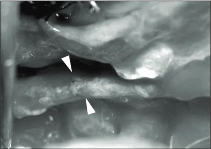
Fig. 1. Right inferior alveolar nerve exposure during sagittal split ramus osteotomy.
Table 1. Patients distribution
Group Patient (n) Mean age (yr) Chin deviation (mm)
Asymmetry HH 8 29.1±4.23 6.3±1.65
HE 18 22.1±3.55 4.5±1.84
Symmetry 20 28.7±11.93
HH, hemimandibular hyperplasia; HE, hemimandibular elonga- tion.
서 론
안면 비대칭은 정준선을 기준으로 반대측 안면 크기, 형태, 배열과의 상관관계로 정의할 수 있다[1]. 안면 비대칭에 영향을 주는 요소로는 상악골 자체의 길이 차이, 하악체 길이의 차이, 하악지 길이의 차이, 두개저 형태의 차이 등이며[2,3], 임상적으로 이러한 요소들은 환자의 성장 방향이나, 성장량에 영향을 준다[4].
안모의 비대칭은 악골과 연관된 현상일 때 더욱 현저하게 나타나 며, 이들은 주로 하악골과 연관되어 나타난다[5].
전통적으로는 안면 비대칭 환자들의 수술을 계획할 때, 안면 비대칭의 요소들을 2차원적인 방사선 사진, 즉 후 전방 두부 방사 선 사진이나, 파노라마, 이하두정 방사선 사진, 두부 규격 방사선 사진들을 통해서 계측했고, 그 변위량을 계산하였다[6-10]. 그러 나 이러한 2차원적인 방사선 사진은 두개악안면 골격의 3차원 형태를 2차원 평면 구조로 나타내기 때문에, 전후방의 구조물 확대 및 왜곡현상이 발생되기 마련이다. 이러한 문제를 극복하기 위하여 여러 연구자들은 2차원 평면사진을 3차원으로 변환시켜 보려는 시도들을 하였다[11,12].
최근의 활발히 사용되는 cone beam computed tomography (CBCT)는 이러한 문제를 극복하는 데 가장 효과적인 장비이다.
이러한 CBCT의 multi-planar reconstruction 이미지는 악골 형 태를 3차원적으로 제공해 줄 뿐만 아니라, 악골 내부의 정보, 특히 치밀골과 해면골의 분포형태, 골질의 변화, 부위별 변형유무 등을 비교적 상세히 제공하기 때문에 안면 비대칭의 진단뿐만 아니라 악교정 수술 시에도 유용하게 사용할 수 있다[13]. 즉, 임상적으로 안면 비대칭 치료를 위한 악교정 수술 시 하악 골체부 에 대한 시상 분절골 절단술은 골편의 절단과 분리의 과정에서 많은 어려움을 야기하는데 이것은 안면 비대칭 환자의 하악 골체 부에는 많은 해부학적 변형이 있으며 이는 악골의 형태적 변이뿐 만 아니라 악골 내부 골질의 변화, 치밀골과 해면골의 분포 형태
변화, 또는 이에 따른 하악관의 위치 변화 때문이라는 것은 널리 알려진 사실이다. 특히, 하악관이 특정부위에서 해면골 내에 존재 하지 않고 치밀골과 근접하여 있거나 부착되어 있는 경우 골편 분리 시 하악관의 손상이 일어날 수 있다(Fig. 1). 그렇기 때문에 하악관의 위치와 하악골의 형태를 술전에 정확히 파악하고 수술에 임하는 것은 매우 중요하며 이와 같이 안면 비대칭 환자에서 하악 단면에 대한 해부학적 이해가 수술 계획 수립 및 합병증 감소에 필수적인 요소이다. 그러나 CBCT를 이용한 하악 골체부 의 시상 단면에 대한 연구는 여러 차례 있어 왔으나 특히, 하악 골체부에서 하악관의 위치 및 형태 변화가 안모 비대칭 환자에서 어떻게 일어날 수 있는가에 대한 연구는 미비한 실정이다.
이에 본 연구의 목적은 CBCT를 이용하여 안면 비대칭을 보이 는 환자의 하악골을 Obwegeser와 Makek[14]의 하악골 분류법 에 따라 분류하여 시상단면상에서 하악관의 위치 및 하악골의 단면적을 변위측과 반대측의 차이가 있는지 알아보고 비대칭이 없는 환자군과 비교 분석하여 이에 대한 술전 고려를 하기 위함이 다.
연구방법
1. 연구대상
본 연구는 2010년 1월부터 2011년 5월까지 원광대학교 치과병 원 구강악안면외과에 내원하여 computed tomography검사를 시행한 환자 중 안면 정중선과 하악 이부 최전방점(chin point, Me) 사이의 차이가 2 mm 이상인 환자 26명을 대상(asymmetry group)으로 하였다[5]. 이 중 Obwegeser와 Makek[14]의 하악 골 분류법에 따라 좌, 우측 치근단에서 하악 하연까지 거리가 증가된 편측 하악골 비대(hemimandibular hyperplasia, HH) 환자가 8명, 좌, 우측 하악지 또는 하악골체부의 길이만 증가된 편측 하악골 신장(hemimandibular elongation, HE) 환자가 18명이었다.
CBCT 분석을 용이하게 하기 위하여 하악 제1, 2대구치의 결손
이 없는 경우를 선별하였다. 또한 구순 구개열이나 기타의 증후군
그리고 외상의 기왕력이 있는 경우는 제외하였다. 대조군으로
뚜렷한 안면비대칭을 보이지 않으며 안면 정중선과 하악 이부
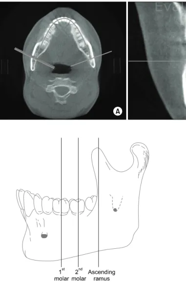
Fig. 2. Converted image by using Ondemand program. (A) Axial image.
(B) Cross-section image.
Fig. 3. Measuring points on body of mandible. Center of 1st molar, center of 2nd molar, anterior border of ascending ramus.
Fig. 4. Measurements in the cross sectional images. (A) Thickness of cancelleous bone in the buccal aspect of the mandible. (B) Thickness of buccal cortex in the buccal aspect of the mandible.
(C) Thickness of cancelleous bone in the inferior aspect of the mandible. (D) Thickness of buccal cortex in the inferior aspect of the mandible. (E) Cross-sectional surface area of the mandible.
최전방점(Me) 사이의 차이가 1 mm 이하, Angle씨 I급 구치 관계를 갖는 정상교합자 20명(남자 11명, 여자 9명)을 본 연구의 대상으로 하였으며 대조군의 평균 연령은 25세 7개월이었다.
평균 이부 변위량은 편측 하악골 비대(HH)에서 6.3 mm, 편측 하악골 신장(HE)에서 4.5 mm였으며, 좌측으로 변위된 경우가 편측 하악골 비대(HH)에서 3명, 편측 하악골 신장(HE)에서 9명, 우측으로 변위된 경우가 편측 하악골 비대(HH)에서 5명, 편측 하악골 신장(HE)에서 13명이었다(Table 1).
2. 연구방법
1) 3차원 영상의 재구성
환자의 진단을 위한 CBCT는 Alphard (Asahi Roentgen Ind.
Co., Ltd., Japan)를 이용하여 노출시간 17 s, 관전압 80 kvp로 촬영되었으며 0.39 mm 간격의 전산화 단층 영상을 DICOM 3.0 file로 전환하여 Ondemand program (Cybermed Inc.,
Seoul, Korea)을 통해 교합평면을 수평면으로 하고, 악궁의 형태 에 수직인 횡단면 영상으로 전환하였다(Fig. 2).
2) 시상면 영상에서의 계측점, 항목
변환된 횡단면 영상에서 측정지점은 제1대구치의 중심, 제2대
구치의 중심, 상행 하악지(ascending ramus)의 최전방점(Me)으
로 하였고(Fig. 3), 연구대상 중 안면 비대칭에서는 이환측과
반대측으로 구분하고 대조군과 각각 하악관과 협측 골수강, 피질
골과의 거리를 측정하였다(Fig. 4). 이 중 편측 하악골 비대(HH)
와 편측 하악골 신장(HE)의 이환측 측정값을 대조군과 비교하였
다(Table 2).
Table 2. Measurements in the asymmetry and symmetry group
Symmetry side
1st molar 2nd molar Ramus
Control A 3.17±1.61 4.72±1.91 3.62±1.55
B 2.27±0.43 2.5±0.55 2.44±0.43
C 4.61±2.06 5.44±2.55 6.31±2.91
D 3.88±0.76 3.99±1.08 3.76±1.08
E 355.71±72.99 364.61±74.88 408.43±89.71
Affected side
1st molar 2nd molar Ramus
HH A 2.04±0.76* 3.1±0.98* 3.34±1.23*
B 2.14±0.48 2.44±0.36 2.42±0.57
C 4.24±2.97* 4.5±3.02* 5.98±3.11*
D 3.2±0.44 3.34±0.48 3.34±0.19
E 314.78±53.22* 324.38±51.34* 368.62±56.91*
HE A 3.34±0.74 4.08±1.38 3.51±1.13
B 2.38±0.33 2.35±0.27 2.57±0.45
C 5.01±1.42 6.23±1.79 7.99±2.02
D 3.41±0.96 3.39±0.51* 3.31±0.42
E 357.1±50.72 348.53±49.54 371.18±58.94
Opposite side
1st molar 2nd molar Ramus
HH A 2.54±1.04 3.26±1.67 3.52±1.35
B 2.08±0.32 2.16±0.24 2.56±0.21
C 4.98±2.96 5.4±3.16 7.1±3.79
D 3.6±0.59 3.32±0.68 3.26±0.23
E 334.52±37.99 303.24±34.84 346.1±43.9
HE A 3.1±1.16 3.95±0.89 3.62±1.31
B 2.27±0.26 2.36±0.37 2.53±0.31
C 5.4±1.01 5.79±1.29 6.93±1.79
D 3.81±0.76 3.19±0.33 3.63±0.73
E 356.42±41.15 352.04±46.26 397.91±82.2
* P <0.05.
Control, symmetry; HH, hemimandibular hyperplasia; HE, hemimandibular elongation; A, thickness of cancelleous bone in the buccal aspect of the mandible (mm); B, thickness of buccal cortex in the buccal aspect of the mandible (mm); C, thickness of cancelleous bone in the inferior aspect of the mandible (mm); D, thickness of buccal cortex in the inferior aspect of the mandible (mm); E, cross-sectional surface area of the mandible (mm2).
3) 통계학적 분석
비대칭군에서 이환측과 대조군의 차이를 비교하기 위해 SPSS version 12 (SPSS Inc., Chicago, IL, USA)를 사용하여 in- dependent t-test (Mann-Whitney U test)를 사용하였다. 이때 P -value가 0.05 이하일 경우 통계적으로 유의하다고 판정하였다.
결 과
대조군의 하악관 협측면에서 협측 해면골까지의 폭경 및 하악 골 협측면에서 피질골의 폭경은 제1대구치 중심, 제2대구치 중심, 하악지 전연에서 각각 3.17 mm, 4.72 mm, 3.62 mm와 2.27 mm, 2.5 mm, 2.44 mm로, 제1대구치에서 제2대구치로 갈수록 증가하였다가 하악지에서 다시 감소하였다. 하악관 하연에서 하
악골 하연 해면골까지의 폭경, 하악골의 단면적은 제1대구치 중 심, 제2대구치 중심, 하악지 전연에서 각각 4.61 mm, 5.44 mm, 6.31 mm와 355.71 mm
2, 364.61 mm
2, 408.43 mm
2로 제1대구 치에서 후방으로 갈수록 증가하였다.
연구대상 중 편측 하악골 비대(HH)의 이환측 계측점에서 하악 관 협측에서 협측 해면골까지의 폭경, 하악관 하연에서 하악골 하연 해면골까지의 폭경, 시상면상 하악골의 단면적은 제1대구치 중심, 제2대구치 중심, 하악지 전연에서 각각 2.04 mm, 3.1 mm, 3.34 mm와 4.24 mm, 4.5 mm, 5.98 mm
2및 314.78 mm
2, 324.38 mm
2, 368.62 mm
2로 모두 제1대구치에서 후방으 로 갈수록 증가하는 양상을 보였다.
연구대상 중 편측 하악골 신장(HE)의 이환측 계측점에서 하악
관 협측에서 협측 해면골까지의 폭경은 제1대구치 중심, 제2대구
치 중심, 하악지 전연에서 각각 3.34 mm, 4.08 mm, 3.51 mm 모두 제1대구치에서 제2대구치로 갈수록 증가하였다가 하악지에 서 다시 감소하였다. 하악관 하연에서 하악골 하연 해면골까지의 폭경은 제1대구치 중심, 제2대구치 중심, 하악지 전연에서 각각 5.01 mm, 6.23 mm, 7.99 mm였고, 제1대구치에서 하악지로 갈수록 증가하였다.
편측 하악골 비대(HH)의 대부분 측정값들은 대조군과 비교하 였을 때 작게 나왔으며, 특히 하악관 협측면에서 협측 해면골까지 의 폭경, 하악관 하연에서 하악골 하연 해면골까지의 폭경 및 하악골의 단면적에서 작게 측정되었다.
편측 하악골 비대(HH)과 대칭군 사이의 관계를 통계학적으로 분석하였을 때 제1대구치 및 제2대구치에서 하악관 협측면에서 협측 해면골까지의 폭경, 하악관 하연에서 하악골 하연 해면골까 지의 폭경 및 하악골의 단면적은 통계학적으로 유의성 있는 차이 를 보였으며 하악지에서는 시상면상 하악골의 단면적만이 통계학 적으로 유의성 있는 차이를 보였다.
편측 하악골 신장(HE)과 대칭군을 비교하였을 때 제2대구치에 서 하악관 부위의 하악골 하연 피질골의 폭경에서 통계학적 차이 를 보였다(Table 2).
고 찰
대칭은 정중선 또는 점에 대하여 마주하고 있는 구조물의 크기 또는 형태 등이 일치하는 경우를 말하며, 비대칭은 그렇지 않는 경우를 말한다[1]. 하지만 안모에 있어서는 정상인도 어느 정도의 비대칭이 존재한다고 이해되고 있고, 이를 normal asymmetry 라고 칭하고 있다. 이러한 안면비대칭은 여러 가지 방법으로 규정 지어질 수 있으나 환자 자신의 안면비대칭에 대한 주관적인 인지 도에 관한 연구에서 하악 이부 편위가 안면비대칭에 가장 큰 영향을 주는 것으로 보고되고 있으며, 안면 정중선에 대하여 하악 이부 최전방점(Chin point, Me)이 2 mm 이상 변위를 보이는 경우에 해당한다[15-17].
Obwegeser와 Makek[14]에 의하면 안면 비대칭 분류를 정상 성장축을 따라서 이환측의 하악지 또는 하악체의 과성장이 발생하 는 편측 하악골 신장(HE)와 이환측 하악골의 전반적인 과성장이 발생하는 편측 하악골 비대(HH)로 표현하였다. 이는 하악골 과성 장의 양상에 따라서 안면 비대칭이 유발됨을 말하고 있다.
Trauner와 Obwegeser[18]가 하악지 시상분할술을 발표한 이 래 많은 구강악안면 외과의들이 안면 비대칭을 치료하기 위하여 하악지 시상분할술을 사용하고 있다[18-20]. 이 술식은 다양한 적용성과, 구강내 수술로 안면반흔이 없다는 점, 많은 골접촉면적 으로 골치유에 유리한 점 등 많은 장점을 가져 오늘날 많은 구강악 안면외과 의사들이 사용하고 있다[20-22]. 그러나, 많은 장점에도 불구하고 많은 술자들은 술 후 합병증 중에서 하순이나 이부의
지각이상이 빈번하고 환자들의 주된 불편감으로 보고하였다. 이 것은 주로 수개월에서 일년 내에 개선되지만 Freihofer와 Pet- reśević[23]은 38명의 환자를 추적 조사한 결과 20%에서는 감각 저하, 2%에서는 감각마비가 있었다고 보고하였다. Broadbent와 Woolf[24]에 의하면 26 case의 환자를 분석한 결과 21명의 환자 가 지각이상을, 9%의 환자가 술 후 1년 이후에도 지각이상이 남아 있었다고 보고하였다. Westermark 등[25]은 하악지 시상 분할술, 구외 수직절단술, 이부성형술, 구내 수직절단술 등의 다양 한 술식에서 환자의 감각이상을 분석하여 시상 분할술 후에 가장 감각이상 발생비율이 높았음을 보고하였다. 또한 Kane 등[26]이 하악 우각부 절제술 시 정상적인 사람에서 하악지에서 하치조신경 의 주행에 대하여 연구하여 전방 후방, 내측, 외측 피질골에서 osseous canal까지의 평균거리가 각각 11.6 mm, 12.1 mm, 1.8 mm, 4.7 mm로 보고하였다.
이와 같이 하악골의 시상 분절골 절단술 시행 시 물리적 또는 신경학적 합병증이 발생될 수 있으며, 이러한 합병증을 줄이기 위해서는 수술 전의 적절한 방사선학적, 임사적 평가가 이뤄져야 한다. 특히, 하악관에 대한 정보는 구강악안면외과 의사가 수술의 위험성 및 하치조 신경의 손상 같은 발생 가능한 합병증을 줄이기 위해서 중요하다[27].
악교정 수술 후 발생하는 지각이상은 술후 가장 큰 합병증으로, 특히 하악지 시상분할 골절단술 시 가장 흔하게 발생한다[28,29].
이러한 지각이상은 하악관의 위치와 관련이 높은데, Yamamoto 등[29]과 Yoshioka 등[29]은 하악골의 협측 피질골과 하악관의 위치가 가까운 환자에서 술 후 지각이상이 높게 발생한다고 하였 으며 협측 피질골과 하악관 사이의 골수강(marrow space)이 0.8 mm 이하인 경우 술 후 1년 이후에도 지각이상이 계속될 수 있다고 하였다.
또한 이전부터 상행 하악지(ascending ramus)의 해부학적 특징(넓이 또는 폭경 등)과 하치조관과의 관계에 대한 연구는 시행되었으며[30], 하악지의 폭경이 클수록 하악관은 협측 치밀골 에서 멀어져 설측에 위치한다고 하였다. 이번 연구에서도 편측 하악골 비대(HH)와 대조군을 비교하였을 때 유사한 결과를 얻을 수 있었다. 하지만 Gowgiel[31]에 의하면 6%의 환자에서 하악지 의 폭경이 크다고 하더라도 하악관의 협설측 위치가 협측 피질골 에 매우 가깝게 위치한다고 하였다.
하악골의 시상 분절골 절단술 시 원심골편과 근심골편의 정확
한 분리를 위해서는 최대한 피질골의 가까운 부위 해면골 내에서
절단이 이뤄져야 하며 하악골 하연의 피질골을 완벽히 절단하여야
한다. 만일 해면골 내측이 아닌 피질골 내에서 절단이 이뤄진다면
예기치 못한 피질골의 부분 파절이 발생할 수 있고 과도하게
해면골 설측으로 절단이 이뤄진다면 하치조 신경의 손상이 발생할
수 있다. 또한 하악골 하연의 피질골이 완벽히 절단되지 않으면
부적절한 시상 분절골 절단술이 이뤄져 하악골 우각부가 원심골편
에 존재할 수 있다.
이번 연구에서 편측 하악골 비대(HH)와 대조군을 비교해 보았 을 때 제1대구치 및 제2대구치에서 하악관 협측에서 협측 해면골 까지의 폭경과 하악관 하연에서 하악골 하연 해면골까지의 폭경이 작은 것으로 나타났고 제1대구치, 제2대구치, 하악지에서 하악골 의 단면적이 작은 것으로 나타났다. 또한 편측 하악골 신장(HE)과 대조군은 비교해 보았을 때 제2대구치에서 하악관 부위의 하악골 하연 피질골의 폭경이 작은 것으로 나타났다( P <0.005).
이러한 결과로 보아 편측 하악골 비대(HH)의 이환측에서 제1 대구치 및 제2대구치 하방의 하치조 신경은 협측에서 주행하고 협측 피질골 사이와의 거리가 좁으며 특히 이 부위에서 해면골이 부족하기 때문에 근심골편과 원심골편을 분리할 때 하악관의 분리 가 용이하지 않아 하치조 신경이 근심골편에 붙어서 분리될 가능 성이 높다는 것을 시사하며 이는 흔히 임상에서 자주 부딪치는 현상이다.
따라서 편측 하악골 비대(HH)의 이환측에서 하악체와 하악지 부위의 단면적이 적고 하악관 협측 해면골의 폭경이 작아서 절골 도(osteotome)를 이용하여 하악골 시상 분절골 절단술 시 한 번에 절단하는 것이 아니라 단계별로 절단술을 시행하여 하악관의 위치를 확인하면서 근심골편과 원심골편을 분리하는 것이 중요하 다. 또한 제1대구치 근심의 하악골 하연에서 수직절단을 시행 시 하악관 하연에서 하악골 하연 해면골의 폭경이 작기 때문에 하악관 손상의 위험성이 증가하기 때문에 피질골 내에서 완벽한 절단이 필요하다.
이번 연구는 안면비대칭 환자의 하악골 수술 시 술 후 발생 가능한 합병증을 줄이기 위해 해부학적 변이를 알아보기 위해 시행하였다. 비대칭 환자와 대조군 사이에는 차이는 존재하였지 만 이는 연구대상이 부족하고 시상 단면의 계측점이 적고 부정확 한 한계가 있기 때문에 향후 더 많은 환자군을 대상으로 추가적인 연구가 필요할 것으로 생각한다.
결 론
본 연구에서는 안면 비대칭 환자를 편측 하악골 비대(HH)와 편측 하악골 신장(HE)으로 구분하고 하악골의 해부학적 정보를 CBCT로 분석하여 다음과 같은 결론을 얻었다.
1. 편측 하악골 비대(HH) 환자에서는 이환측의 제1대구치, 제2대구치 부위에서 하악관이 하악골 하연 및 협측으로 치우쳐서 주행하였다.
2. 편측 하악골 비대(HH) 환자에서는 이환측의 하악체 및 하악지 부위에서 하악골의 단면적이 작았다.
3. 편측 하악골 신장(HE)의 이환측 제2대구치 부위에서 하악 관 하방 하악골 하연의 피질골 폭경이 얇았다.
이렇듯 안면 비대칭 환자에서 하악골의 해부학적 변이가 존재
하므로 안면 비대칭 환자의 시상 분절골 절단술 시 술전 CBCT를 이용한 하악골의 해부학적 변이를 고려하여야 될 것으로 생각한 다.
References