Vol.25 No.2 p108-116, Dec. 2008
안면 비대칭 환자의 하악골 수술 후 하악골 변화에 대한 3차원 CT 영상 비교
김미령⋅진병로
영남대학교 의과대학 치과학교실Comparision of Mandible Changes on Three-Dimensional Computed Tomography image After Mandibular Surgery in Facial Asymmetry Patients
Mi-Ryoung Kim, Byung-Rho Chin
Department of Dentistry,
College of Medicine, Yeungnam University, Daegu, Korea
1)
-Abstract-
Background:When surgeons plan mandible ortho surgery for patients with skeletal class III facial asymmetry, they must be consider the exact method of surgery for correction of the facial asymmetry. Three-dimensional (3D) CT imaging is efficient in depicting specific structures in the craniofacial area. It reproduces actual measurements by minimizing errors from patient movement and allows for image magnification. Due to the rapid development of digital image technology and the expansion of treatment range, rapid progress has been made in the study of three-dimensional facial skeleton analysis. The purpose of this study was to conduct 3D CT image comparisons of mandible changes after mandibular surgery in facial asymmetry patients.
Materials & methods:This study included 7 patients who underwent 3D CT before and after correction of facial asymmetry in the oral and maxillofacial surgery department of Yeungnam University Hospital between August 2002 and November 2005. Patients included 2 males and 5 females, with ages ranging from 16 years to 30 years (average 21.4 years).
Frontal CT images were obtained before and after surgery, and changes in mandible angle
책임저자:진병로, 대구광역시 남구 대명동 317-1, 영남대학교 의과대학 치과학교실 Tel: (053) 620-3282, Fax: (053) 629-1772, E-mail: brchin@med,yu.ac.kr
and length were measured.
Results:When we compared the measurements obtained before and after mandibular surgery in facial asymmetry patients, correction of facial asymmetry was identified on the “after”
images. The mean difference between the right and left mandibular angles before mandibular surgery was 7°, whereas after mandibular surgery it was 1.5°. The right and left mandibular length ratios subtracted from 1 was 0.114 before mandibular surgery, while it was 0.036 after mandibular surgery. The differences were analyzed using the nonparametric test and the Wilcoxon signed ranks test (p<0.05).
Conclusion:The system that has been developed produces an accurate three-dimensional representation of the skull, upon which individualized surgery of the skull and jaws is easily performed. The system also permits accurate measurement and monitoring of postsurgical changes to the face and jaws through reproducible and noninvasive means.
Key Words: Three-dimensional CT image, Facial asymmetry, Mandibular surgery
서 론
수술 전 환자의 안면 및 구강 내 사진, 치아 모형과 방사선 사진, 기능 분석과 같은 진단 방법들을 사용하는 목적은 3차원적인 해부학적 형태를 정확하게 이해하고, 평가하고자 하는 것이다. 그 중 두부규격 방사선 사진은 두개악 안면구조의 크기나 형태를 측정하고 기록하거 나 성장 연구를 위해 가장 널리 사용되는 방법 이다. 이는 3차원적인 입체구조물을 2차원적 평면에 투영하는 것이므로 길이, 각도, 형태의 왜곡현상이 발생하여 정량적인 평가를 할 때 부정확한 결과를 야기할 수도 있다. 이런 2차 원 영상의 한계에 대해서는 1931년 Broadbent
1)가 처음으로 두부계측 방사선 사진을 소개할 때도 언급되었으며, 그 후 많은 저자들에 의해 서 언급되어져 왔다.
2, 3)악교정 수술의 발달로 악안면 기형의 치료 범위가 넓어지면서, 기존의 2차원적인 측모나
정모 두부방사선 규격사진 만으로는 진단과 치 료계획의 수립, 평가 시 한계를 느끼게 되었으 며, 악안면골 형태에 대한 정확한 3차원적인 평가가 필요하게 되었다. 이에 이를 극복하기 위한 일련의 시도들이 계속되었는데, 차등적인 확대를 보상하고자 하는 기준 장치물들이 고안 되기도 하였고, 측면 두부방사선 사진과 더불 어 정모 두부방사선 사진 및 이하 — 두정방사 선 사진을 부가적으로 촬영하여 해부학적인 정 보를 얻기도 하였다.
1, 4-5)그러나 임상가가 머 릿속으로 실제구조를 상상할 수밖에 없었으므 로 3차원적인 영상 정보를 얻기 위한 시도가 여러 연구가들에 의해서 계속되어 졌으며,
6, 7)1994년 Darling 등
8)은 악안면 기형 환자의 검사에 3D CT(three-dimensional computed tomography)가 추가되어야 한다고 하였다.
3D CT의 장점으로는 두개의 경조직과 연조
직의 정확한 부피감을 3차원적으로 묘사해낼
수 있으며, 분석 시 1:1 scale의 real-size,
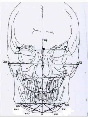
Fig. 1. Landmarks (by Grumone).
ZA:Center of root of zygomatic arch (Right) AZ:Center of root of zygomatic arch (Left) Cg:Crista gali
GA:Point at lateral inferior margin of antegonial protuberance (Right)
AG:Point at lateral inferior margin of antegonial protuberance (Left)
M:Menton
RM1, RM2:Trisection points between GA-M line (Right)
LM1, LM2:Trisection points between AG-M line (left)
real-time으로 분석이 가능하다. 또한 해부학적 구조의 중첩이 없으며, 높은 정확도와 신빙성 을 가진다.
반면, 촬영동안 환자의 수평적 위치에 따라 연조직의 위치 왜곡이 일어날 수 있으며, 구강 내 보철물과 같은 허상에 의해 교합이 자세하 게 나오지 못할 수도 있고, 높은 가격으로 인해 환자에게 일률적으로 적용시킬 수 없으며, 방사 선 조사량도 높은 편인 단점도 가지고 있다.
이 연구에서는 안면비대칭 환자의 진단 시 다양한 장점을 가진 3D CT를 이용하여 안면 비대칭 환자의 악교정 수술 전 후 간단한 분석 을 통해 하악골을 측정하였고, 비대칭성의 정 도가 술 전후에 어떻게 변화하였는지 수치로 나타내어 보았다.
대상 및 방법
이 연구는 2002년 8월부터 2005년 11월까지 영남대학교병원 구강외과에 내원하여 하악골 교정술을 시행한 안면비대칭 환자들 중 술전후 3D CT를 찍은 환자 7명이 선택되었다. 술식의 통일성을 위해 양악 수술이나 이부성형술 같은 부가적인 수술을 시행한 환자들은 제외하고, 양측 하악골 시상분할 골절단술로 하악골 교정 술을 시행한 환자들만 선택되었다. 7명의 환자 들은 2명의 남자와 5명의 여자였으며, 나이는 16세에서 30세까지로 평균 21.4세 였다.
분석 시 기준점은 Fig. 1에 나타나 있다. 정면 상을 중심으로 한 Grumone
9)의 분석법에 따라, 협골-전두골 봉합선(zygomatico-frontal suture) 의 내측면을 Z point로 전악각 함요(antegonial notch)를 GA point로 지정하였고, 좌우측의 Z point를 이은선의 중점에서 수직으로 내려 그
은 선을 수직기준선으로 하여, 이선과 하악 하 연의 교점을 M point로 지정하였다. 하악 하연 의 좀 더 다양한 변화를 보기위해 좌우측 GA point와 M선을 이은 선을 3등분하여 각각 M1, M2로 표시하였다. 좌측의 M1, M2는 LM1, LM2로 정하였고, 우측은 RM1, RM2로 정하였다.
GA point와 이점들을 지나는 각각의 접선을
그어 하악의 각도를 좌우측으로 비교하여 하악
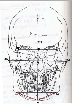
Fig. 2. Comparison of the angles.
ZA:Center of root of zygomatic arch (Right) AZ:Center of root of zygomatic arch (Left)
GA:Point at lateral inferior margin of antegonial protuberance (Right)
AG:Point at lateral inferior margin of antegonial protuberance (Left)
M:Menton
RM1, RM2:Trisection points between GA-M line (Right)
LM1, LM2:Trisection points between AG-M line (left)
Fig. 3. Comparison of the lengths between GA-M and AG-M.
GA:Point at lateral inferior margin of antegonial protuberance (Right)
AG:Point at lateral inferior margin of antegonial protuberance (Left)
M:Menton
GA-M:line between GA and M point AG-M:line between AG and M point
의 비대칭성을 비교하였다(Fig. 2). 또한, 좌우 측 GA point와 M point를 잇는 선을 그어 비 를 계측함으로써 하악골 체부(mandible body) 길이의 비대칭 정도를 측정하였다(Fig. 3).
앞서 설명한 기준점에 따라, 술 전 정면상에 서 좌우측의 각도와 길이를 측정하였고, 술 후 정면상에서도 동일하게 측정하였다.
결 과
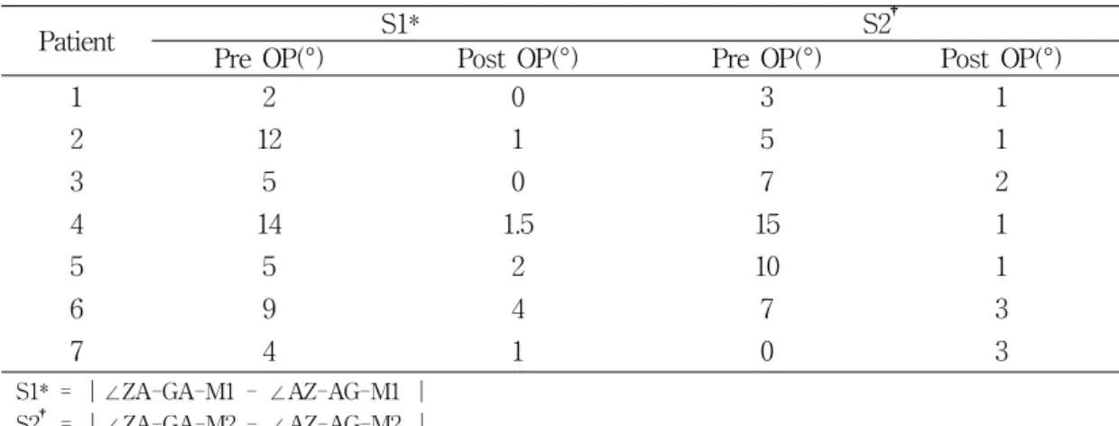
수술 전후에 측정한 하악골의 좌우측 각도 변화가 Table 1에 나타나 있다. 좌우측 Z- GA-M1을 이은 각의 차이를 절대치로 나타낸 값을 간단히 S1이라 하였고, 동일하게 M2를 이은 각의 차이를 절대치로 나타낸 값을 S2라 표시하였다.
술전과 비교하여 술 후의 S1수치가 7명의
환자에서 감소한 것으로 보아, 정면상에서 봤
을 때 환자의 술후 비대칭이 감소함을 볼 수
Patient S1* S2
†Pre OP(°) Post OP(°) Pre OP(°) Post OP(°)
1 2 0 3 1
2 12 1 5 1
3 5 0 7 2
4 14 1.5 15 1
5 5 2 10 1
6 9 4 7 3
7 4 1 0 3
S1* = |∠ZA-GA-M1 - ∠AZ-AG-M1 | S2† = |∠ZA-GA-M2 - ∠AZ-AG-M2 |
ZA:Center of root of zygomatic arch (Right) AZ:Center of root of zygomatic arch (Left)
GA:Point at lateral inferior margin of antegonial protuberance (Right) AG:Point at lateral inferior margin of antegonial protuberance (Left) M1, M2:Trisection points between AG-M, GA-M line
Table 1. Comparison of the differences between the mandibular angle of before and after the mandibular surgery.
Patient Pre OP Post OP
/
D1*
/
D2
†1 0.933 0.067 0.954 0.046
2 0.931 0.069 0.986 0.014
3 0.847 0.153 0.926 0.074
4 1.132 0.132 1.071 0.071
5 1.117 0.117 1.014 0.014
6 0.908 0.092 0.986 0.014
7 1.167 0.167 0.984 0.016
D1* = |1- ( / )|
D2† = |1- ( / )|
GA : Point at lateral inferior margin of antegonial protuberance (Right) AG : Point at lateral inferior margin of antegonial protuberance (Left) M : Menton
Table 2. Comparison of the difference between the mandibular length of before and after the mandibular surgery.
있으며, S2의 수치 또한 감소한 것으로 보아, 하악 하연에 남아 있을 것이라 예상한 술후 비 대칭양도 술전과 비교하여 많이 감소한 것으로
보인다. 이는 이부성형술 같은 하악하연교정술
을 부가적으로 시행하지 않아도 안면비대칭 환
자에서 하악교정술 후 어느 정도의 비대칭성의
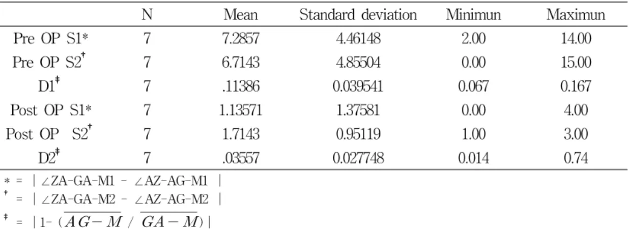
N Mean Standard deviation Minimun Maximun
Pre OP S1* 7 7.2857 4.46148 2.00 14.00
Pre OP S2
†7 6.7143 4.85504 0.00 15.00
D1
‡7 .11386 0.039541 0.067 0.167
Post OP S1* 7 1.13571 1.37581 0.00 4.00
Post OP S2
†7 1.7143 0.95119 1.00 3.00
D2
‡7 .03557 0.027748 0.014 0.74
* = |∠ZA-GA-M1 - ∠AZ-AG-M1 |
† = |∠ZA-GA-M2 - ∠AZ-AG-M2 |
‡ = |1- (
/
)|ZA:Center of root of zygomatic arch (Right) AZ:Center of root of zygomatic arch (Left)
GA:Point at lateral inferior margin of antegonial protuberance (Right) AG:Point at lateral inferior margin of antegonial protuberance (Left) M1, M2:Trisection points between AG-M, GA-M line
Table 3. Nonparametric test
감소가 일어남을 의미하며, 앞으로 좀 더 연구 가 필요할 것으로 보인다.
하악골 수술 전, 후의 하악의 좌우측 길이 변화량은 좌우측 GA point와 M을 이은 직선 의 길이 값을 분수로 나타내었는데, 완벽한 대 칭값인 1에서 이 수치를 뺀 값의 절대치를 술 전 D1, 술후 D2로 표기하였다(Table 2). D2의 수치가 D1보다 감소하는 것으로 보아 하악의 길이 역시 술후 대칭적으로 변화하는 것을 수 치로 확인할 수 있었다.
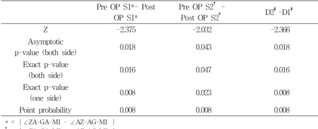
각도와 선의 값의 술전후 대칭적으로 변화 한 것이 통계적으로 유의한 것인지 확인하기위 해 비모수 검정을 통한 Wilcoxon Signed Ranks test를 시행하여 P-value 0.05 이하인 유효한 수치임을 확인하였다(Table 3).
고 찰
안면비대칭의 접근에 대해서도 여러 학자들
이 논한 바 있다. 1991년 Pecks 등
10)과 1997년 Severt와 Proffit
11)은 정면상이 안면비대칭에 대한 각과 선수치를 측정하는데 가장 적합하다 고 하였으며, 1997년 Meredith
12)역시 facial symmetry, dissymmetry, asymmetry를 인지 하는데 정면상을 사용해야 한다고 하였다.
Dissymmetry는 얼굴의 좌우 폭과 길이의 차
이가 약간 있으나 전체적인 조화를 이루는 경
우라 하였고, asymmetry는 적어도 하나 이상
의 면적의 차이가 있으며, 확연이 드러나는 부
조화를 인지할 수 있는 경우로 이 두 가지는
구분되어져야 한다고도 했다. 이 연구에서는
M2 point에서 술전후 각도의 변화는 이런
dissymmetry 환자들에게서 나타나는 것으로
보이며, 이런 환자들에게서는 술후 하악 하연
의 보정을 어느 정도 감안하여 하악골 수술시
이부 성형술과 같은 부가적 술식은 1차 수술
후 고정판 제거술과 같은 2차 수술시 고려하는
것이 좋을 것으로 보인다. 하지만 정확한 환자
Pre OP S1*- Post OP S1*
Pre OP S2
†-
Post OP S2
†D2
‡-D1
‡Z -2.375 -2.032 -2.366
Asymptotic
p-value (both side) 0.018 0.043 0.018 Exact p-value
(both side) 0.016 0.047 0.016
Exact p-value
(one side) 0.008 0.023 0.008
Point probability 0.008 0.008 0.008
* = |∠ZA-GA-M1 - ∠AZ-AG-M1 |
† = |∠ZA-GA-M2 - ∠AZ-AG-M2 |
‡ = |1- ( / )|
ZA:Center of root of zygomatic arch (Right) AZ:Center of root of zygomatic arch (Left)
GA:Point at lateral inferior margin of antegonial protuberance (Right) AG:Point at lateral inferior margin of antegonial protuberance (Left) M1, M2:Trisection points between AG-M, GA-M line
Table 4. Wilcoxon signed ranks test
의 분류나 그 근거는 좀 더 많은 연구가 필요 하다.
2002년 Dahan
13)도 안면비대칭을 접근하는데 가장 유용한 진단방법은 정면상을 사용하는 것 이라 하였으며, 최근 Edler 등
14)은 디지털화된 정면상을 사용하여 하악의 외형에 대한 좌우측 의 비를 얻는 것이 하악 비대칭에 접근하는 유 용한 방법이 될 것이라고 하면서, 이에 관해서 는 좀 더 다양한 연구가 필요할 것이라고도 하 였다.
CT로 촬영된 영상의 정확도에 대해서 여러 연구가 진행되었는데, 1995년 Richtsmeier 등
15)이 발표한 이후부터 여러 학자들이 CT영상의 전반적인 오차는 무시할 만하다고 보고했다.
16, 17)다만, 1996년 Kragskov 등
18)은 안면골에서 2 차원적인 측면두부 방사선 영상보다 3D CT가
좀 더 정확하다는 근거는 보이지 않으나, CT 이미지의 장점 때문에 안면비대칭을 보이거나 악안면 신드롬에 연관된 환자는 3D CT를 부 가적으로 찍는 것이 좋다고 발표하였다.
이 연구에서는 안면비대칭을 가진 환자의 수술 전후 3D CT의 정면상을 통해 하악골 교 정술 후 대칭성의 변화를 좀 더 정확히 관찰 할 수 있었다.
결 론
안면 비대칭 환자에서 3차원 CT영상을 구 성하고 계측하는 것은 임상적으로 유용하며, 특히 정면상은 비대칭의 정도를 진단하는데 더 욱 용이하게 사용될 수 있을 것으로 생각된다.
수술 전후 좌우측의 Z-GA-M1의 각도의 차
이가 줄어드는 것과, GA와 M사이의 거리의 비도 1에 가까워지는 것으로 보아 안면 비대칭 환자에서 악교정 수술 후 하악골의 대칭적인 변화를 확인 할 수 있었다.
수술 전후 좌우측의 Z-GA-M2의 각도의 차 이가 줄어드는 것은 안면비대칭 환자의 악교정 수술 직후 하악골하연에 남아 있는 비대칭이 술 후 시간이 지남에 따라 어느 정도 감소하는 것으로 보이며, 이는 추후 연구가 필요할 것으 로 사료된다.
참 고 문 헌
1. Broadbent BH. A new x-ray technique and its application to orthodontia. Angle Orthod 1931 Apr;1(2):45-66
2. Hatcher DC. Maxillofacial imaging. In: McNeill C, ed. Science and Practice of Occlusion.
Chicago: Quintessence Publishing; 1997. p.349-64.
3. Vig PS. Orthodontic controversies : Their origins, consequences, and resolution. In: Melsen B, ed. Current Controversies in Orthodontics.
Chicago: Quintessence Publishing; 1991. p.269- 310.
4. Wylie W.H. , Elasser W.A. Understated vertical projections of the head from lateral and posteroanterior roentogenograms. Am J Roentenol 1948 Sep;60(3):414.
5. Vogel CJ. Correction of frontal dimensions from head x-rays. Angle Orthod 1967 Jan;
37(1):1-8.
6. Grayson BH, McCarthy JG, Bookstein F.
Analysis of craniofacial asymmetry by multiplane cephalometry. Am J Orthod 1983 Sep;84(3):
217-24.
7. Brown T, Abbott AH. Computer assisted location of reference points in three dimensions
for radiographic cephalometry. Am J Orthod Dentofacial Orthop 1989 Jan;95(6):490-8.
8. Darling CF, Byrd SE, Allen ED. Three dimensional computed tomography imaging in the evaluation of craniofacial abnormality. J Natl Med Assoc 1994 Sep;86(9):676-80.
9. Grumone DC. Kappeyne van de Coppello MA.
A Frontal asymmetry analysis. J Clin Orthod 1987 Jul;21(7):448-65.
10. Peck S, Peck L, Kataja M. Skeletal asymmetry in esthetically pleasing faces. Angle Orthod 1991 Spring;61(1):43-7.
11. Severt TR, Proffit WR. Postsurgical stability following correction of severe facial asymmetry.
Int J Adult Orthod Orthognath Surg 1997;12 (4):251-61.
12. Meredith G. Facial photography for the orthodontic office. Am J Orthod Dentofacial Orthop 1997 May;11(5):463-70.
13. Dahan J. A simple digital procedure to assess facial asymmetry. Am J Orthod Dentofacial Orthop 2002 Jul;122(1):110-6.
14. Edler R, Wertheim D, Greenhill D. Outcome measurement in the correction of mandibular asymmetry. Am J Orthod Dentofacial Orthop 2004;125:435-43.
15. Richtsmeier JT, Paik CH, Elfert PC, Cole TM 3rd, Dahlman HR. Precision, repeatability, and validation of the localization of cranial landmarks using computed tomography scans.
Cleft Palate Craniofac J 1995 May;32(3):
217-27.
16. Williams FL, Richtsmeier JT. Comparison of mandibular landmarks from computed tomography and 3D digitizer data. Clin Anat 2003 Nov;16 (6):494-500.
17. Cavalcanti MG, Rocha SS, Vanier MW.
Craniofacial measurements based on 3D-CT volume rendering: implications for clinical applications. Dentomaxillofac Radiol 2004 May;
33(3):170-6.
18. Kragskov J, Sindet-Pedersen S, Gyldensted C, Jensen CL. A comparison of three-dimensional computed tomography scans and stereolitho-
graphic models for evaluation of craniofacial anomalies. J Oral Maxillofac Surg 1996 Apr;54(4):402-11.