Design of the Helium Cooled Molten Lithium TBM for ITER in Korea
a)Dong Won Lee, Bong Geun Hong, Keun Wu Song, Yong Hi Kim, Ki Nam Song, Wang Ki In, and Kyung Ho Yoon a)Korea Atomic Energy Research Institute
Deokjin-dong, Yuseong-gu, Daejeon, 305-600, Republic of Korea 1. Introduction
One of the main engineering performance goals of International Thermonucler Experimental Reactor (ITER) is to test and validate design concepts of tritium breeding blankets relevant to a power producing reactor. The tests will foresee on modules including the demonstration of a breeding capability that would lead to tritium self heat suitable for electricity generation.
The test blanket modules (TBMs) have been proposed by several parties. And the proposed TBMs by each party will be located in the common frame of ITER ports such as port no. 1, 2, and 18 with the thickness of 200 mm. We have been designing the own TBMs such as Helium Cooled Solid Breeder (HCSB) and Helium Cooled Molten Lithium (HCML) [1]. In this paper, the latter one is explained with regard to the design procedure and its analysis.
2. Design and Analysis of KO HCML
Figure 1 depicts the schematic of the KO HCML TBM concept. The whole TBM is cooled only by the He coolant and the molten Li is used only as the tritium breeder. It is well known that liquid Li is compatible with the steel up to 550 oC. Due to the low speed of the
molten Li, there are no serious MHD and material corrosion issues. With the HCML TBM concept, the heat exchanger design is relatively simple since the liquid Li is not involved in the heat removal.
Plasma
side 514
378 (443 ; inc. FW, BeA & BW)
Li Gr Li Separation plate Grid Plate (30mm) 2030 125 3018 30 30 217 125 30 Be Armor 5
Figure 1. The KO HCML TBM concept
As in the HCSB TBM concept, a graphite reflector is also used in this HCML TBM concept in order to minimize the neutron leakage from the TBM. Based on the neutronics analysis, the graphite reflector is placed such that the TBR is maximized: a thick front region and a thin back breeder. In the ITER machine, the Li
inventory is limited due to the safety reasons, the amount of Li in the HCML TBM is about 28 liters, which satisfies the Li limit. The Li-6 enrichment in the current design is 12 wt%, corresponding to an optimal value in terms of the TBR. It is expected that the Li speed will be very slow, less than a few mm/sec for the design. The graphite is used as a reflector.
For the model in Fig. 1, a 3-D Monte Carlo analysis was done with the MCCARD code. The design data and nuclear performance of HCML are given in Table 1. The total heat deposition is substantially lower than in the HCSB case since the HCML TBM does not contain any neutron multiplier, i.e. Be. Also, the TBR of the TBM is less than unity. This is mainly because the Li inventory is limited in the ITER design. In the actual DEMO-like design, the front Li breeder region could be significantly expanded for a higher value of the TBR. However, a low TBR does not matter in the TBM because the main purpose of the TBM is to confirm the first principle of the proposed TBM. As a result, the tritium production rate is relatively small, too.
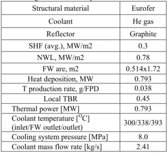
Table 1. Design data and nuclear performance of HCML
Structural material Eurofer
Coolant He gas Reflector Graphite SHF (avg.), MW/m2 0.3 NWL, MW/m2 0.78 FW are, m2 0.514x1.72 Heat deposition, MW 0.793 T production rate, g/FPD 0.038 Local TBR 0.45 Thermal power [MW] 0.793 Coolant temperature [OC] (inlet/FW outlet/outlet) 300/338/393
Cooling system pressure [MPa] 8.0
Coolant mass flow rate [kg/s] 2.41
Thermal-hydraulic analysis was also performed in order to calculate the temperature distribution of the first wall and the breeding zone using the CFD code, CFX-5.7. Figure 2 shows the He flow paths in the entire HCML and first wall. The helium coolant flows through the first wall and then the half amount of inlet He flows the breeding zone in a poloidal direction at a static pressure of 8 MPa. When the inlet temperature is assumed to be 300 oC, the He temperatures is 338.1 oC
at the first wall exit. The coolant flow rate for the HCML with a thermal power of 0.77 MW and the Transactions of the Korean Nuclear Society Autumn Meeting
coolant velocity of 45 m/sec is 2.41 kg/s. The thermal-hydraulic design parameters of the KO HCML are summarized in Table 1.
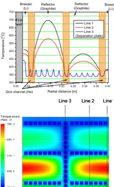
The temperature distributions of the HCML were calculated using the 3D model of first wall and breeding zone, separately. The average surface heat flux of 0.3 MW/m2 from a plasma is applied to the
surface of the Be armor. The helium coolant temperatures used in this analysis are 325.4 oC and
338.1 oC in the first wall channel and the breeding
channels, respectively. Figures 3 and 4 show the predicted temperature distributions at each region. The peak temperatures were predicted to be 508.7 oC in the
first wall contacting with Be armor and 700 oC in the
front graphite reflector of breeding zone, respectively. The pressure drop of the coolant in the HCML should be evaluated in the future.
Using the CFD model of the first wall for the HCML, a finite element model for the thermal analysis was created by ANSYS Version 9.0. The boundary conditions are determined from the results of CFX-5 analysis. Figure 5 shows the calculated thermal deformation and stress distributions. The maximum von Mises equivalent stress of the first wall showed at 123 MPa and the maximum deformation of it was 3.73 mm. This result from the preliminary thermo-mechanical analysis is lower than the maximum allowable stress.
Back wall FW 6 groups 2 paths Cover (top) Grid plate Cover (bottom) Back wall 2.41kg/sec 45 m/sec Qbypass=1.25kg/sec QBZ=1.16kg/sec 7.8 m/sec 1 Group : 11 channel total 6 groups, 66 chs Group 1 Group 2 Group 3 Group 4 Group 5 Group 6 3 2 1 1 2 3 TFW,max=483.7 TFW,max=496.4 TFW,max=509.1 THe=338.1 THe=325.4 THe=312.7 THe=300(inlet)
Figure 2. He flow scheme and its temperature at each position
He inlet He outlet
Figure 3. Computational model and temperature distribution for the first wall of the KO HCML
0.00 0.05 0.10 0.15 0.20 0.25 0.30 0.35 0.40 300 350 400 450 500 550 600 650 700 750 Reflector (Graphite) Te m p er at ur e [ OC] Radial distance [m] Line 1 Line 2 Line 3 (Separation plate) Breeder (Li)
Grid channel (He)
Reflector (Graphite) First wall Breeder (Li)
Line 3 Line 2 Line 1 Line 3 Line 2 Line 1
Figure 4. Calculated temperature distribution for the KO HCML
Figure 5. Thermal deformation and stress distributions for the first wall of the KO HCML
4. Conclusion
In order to participate the test program of tritium breeding blanket in ITER, we have been designing our own HCML TBM with regard to the Be amount and Graphite application, and the concepts are investigated in terms of neutronics, thermal-hydraulics, and thermo-mechanics. The final design of HCML TBM will be completed through the above procedure. In accordance with the TBM R&D and test plan, the followings will be developed; tritium recovery, fabrication of mock-ups, MHD coating, V-alloy and so on.
REFERENCES
[1] D. W. Lee, et. al., “Current status and R&D plan of ITER TMBs of Korea,” Proc. of Korea Nuclear Society, Jeiu, Korea, May 2005,
[2] TBWG members, Reprots form the TBWG for the Period of Extension of the EDA, ITER-FEAT, May 2001.
[3] L.V. Boccaccini et. al, Design Description Document for the European Test Blanket Module, June 2001.
[4] JAERI, Design Description Document for the Japanese Test Blanket Module, April 2001.
[5] Abramov V. et. al, Design Description Document for the Russian Federation Test Blanket Module, 2001.
[6] Personal Communication at 2nd Japan-Korea workshop on