http://dx.doi.org/10.5624/isd.2015.45.4.227
Introduction
Since symmetry is considered to be an essential element of an esthetic and attractive face, establishing a symmet- ric face is one of the main goals of orthodontic treatment.
Orthognathic surgery is currently a popular method for improving facial symmetry. The accurate analysis of fa- cial asymmetry is an essential step in orthognathic surgery planning and post-treatment evaluation. Facial asymme- try has traditionally been evaluated using posteroanterior
cephalometric radiography.1-3 The location of the menton (Me) has been shown to have a significant association with the perception of asymmetry, and deviation of the Me from the facial midline has been considered the most important indicator of facial asymmetry.4,5 The deviation of the Me has usually been measured as the distance or angle of the Me from the midfacial line.1,6-10 Two-dimensional(2D) cephalometric radiography has been used for the analysis of facial asymmetry; however, it is limited in its utility for analyzing three-dimensional(3D) human structures.1,11
Three-dimensional computed tomography(CT) has none of the inherent problems of 2D radiography, such as super- imposition, magnification, and distortion. Measurements made with 3D CT images show high conformity to mea- surements made on dry bones, with high repeatability and
The location of midfacial landmarks according to the method of establishing the midsagittal reference plane in three-dimensional computed tomography analysis of facial asymmetry
Min Sun Kim1, Eun Joo Lee2, In Ja Song3, Jae-Seo Lee4, Byung-Cheol Kang4, Suk-Ja Yoon4,*
1School of Dentistry, Dental Science Research Institute, Chonnam National University, Gwangju, Korea
2Department of Oral Anatomy, School of Dentistry, Dental Science Research Institute, Chonnam National University, Gwangju, Korea
3Department of Nursing, Kwangju Women’s University, Gwangju, Korea
4Department of Oral and Maxillofacial Radiology, School of Dentistry, Dental Science Research Institute, Chonnam National University, Gwangju, Korea
AbsTrAcT
Purpose: The purpose of this study was to evaluate the influence of methods of establishing the midsagittal reference plane(MRP) on the locations of midfacial landmarks in the three-dimensional computed tomography(CT) analysis of facial asymmetry.
Materials and Methods: A total of 24 patients(12 male and 12 female; mean age, 22.5 years; age range, 18.2-29.7 years) with facial asymmetry were included in this study. The MRP was established using two different methods on each patient’s CT image. The x-coordinates of four midfacial landmarks(the menton, nasion, upper incisor, and lower incisor) were obtained by measuring the distance and direction of the landmarks from the MRP, and the two methods were compared statistically. The direction of deviation and the severity of asymmetry found using each method were also compared.
results: The x-coordinates of the four anatomic landmarks all showed a statistically significant difference between the two methods of establishing the MRP. For the nasion and lower incisor, six patients(25.0%) showed a change in the direction of deviation. The severity of asymmetry also changed in 16 patients(66.7%).
conclusion: The results of this study suggest that the locations of midfacial landmarks change significantly according to the method used to establish the MRP.(Imaging Sci Dent 2015; 45: 227-32)
Key words: Facial Asymmetry; Anatomic Landmarks; Tomography, X-Ray Computed
Copyright ⓒ 2015 by Korean Academy of Oral and Maxillofacial Radiology
This is an Open Access article distributed under the terms of the Creative Commons Attribution Non-Commercial License(http://creativecommons.org/licenses/by-nc/3.0) which permits unrestricted non-commercial use, distribution, and reproduction in any medium, provided the original work is properly cited.
Imaging Science in Dentistry·pISSN 2233-7822 eISSN 2233-7830 Received July 14, 2015; Revised August 22, 2015; Accepted September 2, 2015
*Correspondence to : Prof. Suk-Ja Yoon
Department of Oral and Maxillofacial Radiology, School of Dentistry, Chonnam Na- tional University, 33 Yongbong-ro, Buk-gu, Gwangju 61186, Korea
Tel) 82-62-530-5680, Fax) 82-62-530-5689, E-mail) [email protected]
accuracy.11-13 Furthermore, 3D volumetric imaging allows human structures to be viewed at multiple angles.1,14 Pre- vious studies have demonstrated that 3D CT is more ef- fective than cephalometric radiography for analyzing fa- cial asymmetry.15,16
Various methods for analyzing facial asymmetry using 3D CT have been recently introduced.1,7-10,14 The first step in analyzing facial asymmetry is to establish reference planes. The midsagittal reference plane(MRP) is the most critical reference plane for the diagnosis of facial asym- metry, as the lateral deviation of facial landmarks is mea- sured from the MRP. Therefore, establishing the MRP is the most fundamental step in making a correct diagnosis of facial asymmetry.
The method of establishing the MRP has varied among researchers; however, two main methods have been com- monly applied. One method is to first establish the hori- zontal reference plane(HRP) using three facial landmarks and to then establish the MRP by using two midfacial land- marks so that it is perpendicular to the HRP. The other method is to establish the MRP by using three midfacial landmarks.1,7-10,14
Although establishing the MRP is the first fundamental step in the accurate analysis of facial asymmetry, only a few studies have assessed the methods of establishing the
MRP.17,18 Therefore, this study aimed to investigate the in-
fluence of the method of establishing the MRP on the loca- tion and measurement of facial landmarks through a com- parison of two different methods of establishing the MRP.
Materials and Methods
The CT scans of twenty-four patients(12 male and 12 female; mean age, 22.5 years; age range, 18.2-29.7 years) who were treated with orthognathic surgery for facial asymmetry at Chonnam National University Dental Hospi-
tal from 2000 through 2007 were reviewed for this study.
The CT scans were obtained using a spiral CT scanner (Light Speed QX/I; GE Medical Systems, Milwaukee, WI, USA) with a 512×512 matrix. The imaging parameters were 120kV, 200mAs, and a gantry angle of 0°. The axial image slice thickness was 2.5mm, the table speed was 3 mm/s, and the scanning time was 0.8s. Digital Imaging and Communication in Medicine(DICOM) images were acquired with a slice thickness of 1.0mm. The acquired DICOM data were transferred to a personal computer, and 3D images were constructed from the CT data with the software program Vworks+Vsurgery(Cybermed, Seoul, Korea).
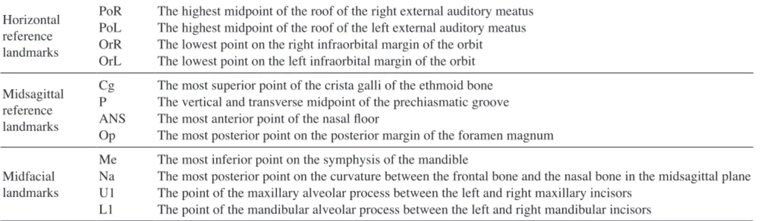
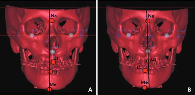
The surface shaded display was obtained with a thresh- old value of 126. Facial landmarks were identified and their location was confirmed on the axial, sagittal, and coronal planes. On each CT scan, horizontal reference landmarks(the right porion[PoR], left porion[PoL], right orbitale[OrR], and left orbitale[OrL]), midsagittal refer- ence landmarks(crista galli[Cg], the prechiasmatic groove [P], anterior nasal spine[ANS], and opisthion[Op]), and midfacial landmarks(Me, nasion[Na], upper incisor[U1], and lower incisor[L1]) were identified(Table 1). Two distinct methods(Methods 1 and 2) of establishing the MRP were applied for each CT scan(Fig. 1). In Method 1, the PoR, PoL, and OrL landmarks were used to establish the horizontal reference plane(HRP), the Cg and P were used to establish the MRP, and the Op was used for estab- lishing the coronal reference plane(CRP), with the three planes perpendicular to one another on Vworks. All of the data for the landmarks and planes were transferred to Vsurgery. In Method 2, the Op, Cg, and ANS landmarks were used to establish the MRP on Vsurgery for each CT scan, using the same values of Op and Cg as Method 1 (Table 2).
The x-coordinate, severity of asymmetry, and direction
Table 1. Anatomic landmarks used in this study Horizontal
reference landmarks
PoRPoL OrROrL
The highest midpoint of the roof of the right external auditory meatus The highest midpoint of the roof of the left external auditory meatus The lowest point on the right infraorbital margin of the orbit The lowest point on the left infraorbital margin of the orbit Midsagittal
reference landmarks
CgP ANSOp
The most superior point of the crista galli of the ethmoid bone The vertical and transverse midpoint of the prechiasmatic groove The most anterior point of the nasal floor
The most posterior point on the posterior margin of the foramen magnum
Midfacial landmarks
MeNa U1L1
The most inferior point on the symphysis of the mandible
The most posterior point on the curvature between the frontal bone and the nasal bone in the midsagittal plane The point of the maxillary alveolar process between the left and right maxillary incisors
The point of the mandibular alveolar process between the left and right mandibular incisors
of deviation of the Me were compared between the two methods as follows. First, the x-coordinate of the Me was considered to be(+) when the landmark was located on the left side of the face and(-) when on the right. Then, Δx was defined as the difference between the x-coordi- nates calculated with Method 1(x1) and Method 2(x2). The severity of asymmetry was considered to be normal when the distance of the Me from the MRP(
|
x|
) was less than 2mm(0mm≤|
x|
<2mm), mild when less than 4mm (2mm≤|
x|
<4mm), moderate when less than 8mm(4 mm≤|
x|
<8mm), and severe at values of 8mm or higher (8mm≤|
x|
).4 The direction(left or right) of the devia- tion of the Me was compared between the two methods.The x-coordinates and directions of deviation for the Na, U1, and L1 were compared between the two methods in the same way as described above for the Me.
The one-sample t-test was performed using SPSS(IBM Corp., Armonk, New York, USA) to evaluate whether the Δx of the Me, Na, U1, and L1 landmarks varied to a sta-
tistically significant extent between the two methods.
results
CT scans were obtained from 24 orthodontic patients with facial asymmetry, and 3D reconstructions of the CT scans were performed. Two methods of establishing the MRP were applied for each CT scan. The midfacial land- marks(the Me, Na, U1, and L1) were identified, and the x-coordinates and the direction of deviation of each land- mark relative to the MRP were compared between the two methods(Fig. 1, Tables 3-5).
The direction of deviation for the Me was the same in both methods for all patients. The severity of asymmetry was the same in both methods in eight patients(33.3%).
Differences were found in the severity of asymmetry in 16 patients(66.7%), with a difference of two or more stages in three patients(12.5%). The mean Δx was 2.77±
0.49mm, and a statistically significant difference was
Table 2. Reference planes used in Methods 1 and 2
Method 1 Horizontal reference plane(HRP) Midsagittal reference plane(MRP) Coronal reference plane
Intersecting the PoR, PoL, and OrL
Perpendicular to the HRP and intersecting the Cg and P Perpendicular to the HRP and MRP, and intersecting the Op Method 2 Midsagittal reference plane Intersecting the Op, Cg, and ANS
PoR: right porion, PoL: left porion, OrL: left orbitale, Cg: crista galli, P: prechiasmatic groove, Op: opisthion, ANS: anterior nasal spine.
Fig. 1. The establishment of the midsagittal reference plane by two methods. A. In Method 1, the horizontal reference plane is establish ed using the PoR, PoL, and OrL landmarks, the midsagittal reference plane(MRP) by using the Cg and P, and the coronal reference plane by using the Op. The planes are perpendicular to one another. B. In Method 2, the Op, Cg, and ANS landmarks identified in Method 1 are used to establish the MRP. Midfacial landmarks are indicated as circles, and the MRP is shown as a black vertical line. PoR: right porion, PoL:
left porion, OrL: left orbitale, Cg: crista galli, P: prechiasmatic groove, Op: opisthion, ANS: anterior nasal spine.
A B
found between the methods(p<0.05). The value of Δx was between 2mm and 4mm in nine patients(37.5%), between 4mm and 8mm in three patients(12.5%), and 8 mm or more in two patients(8.3%)(Tables 3-5).
The direction of deviation for the Na was the same in both methods in 18 patients(75.0%), and different be- tween the two methods in six patients(25.0%). The mean Δx was 0.92±0.17mm, and a statistically significant dif- ference was found between the methods(p<0.05). The value of Δx was between 2mm and 4mm in two patients (8.3%)(Tables 3 and 4).
The direction of deviation for the U1 was the same in both methods for all patients. The mean Δx was 1.88±
0.39mm, and a statistically significant difference between the methods was observed(p<0.05). The value of Δx was between 2mm and 4mm in five patients(20.3%) and bet-
ween 4mm and 8mm in three patients(12.5%)(Tables 3 and 4).
The direction of deviation for the L1 was the same in both methods in 18 patients(75.0%), and different bet- ween the two methods in six patients(25.0%). The mean Δx was 3.60±0.61mm, and a statistically significant difference was observed between the methods(p<0.05).
The value of Δx was between 2mm and 4mm in three patients(12.5%), between 4mm and 8mm in eight pa- tients(33.3%), and 8mm or more in two patients(8.3%) (Tables 3 and 4).
discussion
As a result of the recent increase in the general socie- tal interest in esthetic appearance, the number of patients whose primary complaint is facial asymmetry is rising. The usage of CT has been extended to the 3D analysis of fa- cial asymmetry,19,20 which is performed by first establish- ing the appropriate reference planes, of which the MRP is the most fundamental. Several methods for establishing reference planes have been introduced for the 3D analysis of facial asymmetry.1,7-10,14,21 The results of facial asym- metry analysis using CT can be influenced by the method chosen for establishing the reference planes, similarly to the influence of reference lines on facial asymmetry anal- ysis when using 2D radiographs.17,18 However, very few studies have evaluated the different methods used to de- termine the reference planes.17,18,21
Therefore, this study compared the two most common methods(Method 1 and Method 2) of establishing the MRP and evaluated changes in the location of facial land- marks relative to the MRP according to the method of establishing the MRP. This evaluation was conducted by obtaining the x-coordinates of the midfacial landmarks Me, Na, U1, and L1, which can be used as reference points for analyzing facial asymmetry. The direction of deviation
Table 4. The difference(Δx) of the measurements of the Me bet- ween Method 1(x1) and Method 2(x2)
Δx(mm) 0-2 2-4 4-8 8 or over Total
MeNa U1L1
10(41.7%) 22(91.7%) 16(66.7%) 11(45.8%)
9(37.5%) 2(8.3%) 5(20.3%) 3(12.5%)
3(12.5%) - 3(12.5%) 8(33.3%)
2(8.3%) - - 2(8.3%)
24(100%) 24(100%) 24(100%) 24(100%) x1: the x-coordinate as calculated by Method 1, x2: the x-coordinate as cal- culated by Method 2, Me: menton.
Table 5. Comparison of the severity of the Me deviation between Method 1 and Method 2
Method 1 Method 2
Normal Mild Moderate Severe Total Normal
MildModerate Severe
12 1 -
12 4 -
-1 33
2 - 22
4(16.7%) 5(20.8%) 10(41.7%) 5(20.8%) Total 4(16.7%) 7(29.2%) 7(29.2%) 6(25.0%) 24(100%) Me: menton.
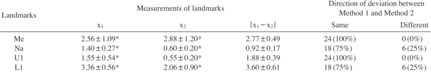
Table 3. Comparisons between Method 1 and Method 2 of the measurements of the Me, Na, U1, and L1and the direction of deviation for midfacial landmarks
Landmarks Measurements of landmarks Direction of deviation between
Method 1 and Method 2
x1 x2 |x1-x2| Same Different
MeNa U1L1
2.56±1.09*
1.40±0.27*
1.55±0.54*
3.36±0.56*
2.88±1.20*
0.60±0.20*
0.55±0.20*
2.06±0.90*
2.77±0.49 0.92±0.17 1.88±0.39 3.60±0.61
24(100%) 18(75%) 24(100%) 18(75%)
0(0%) 6(25%) 0(0%) 6(25%) x1: the x-coordinate as calculated by Method 1, x2: the x-coordinate as calculated by Method 2, Me: menton, Na: nasion, U1: upper incisor, L1: lower inci- sor; *p<0.05.
and the severity of asymmetry of each landmark was also evaluated according to each of the methods.
In the comparison of these two methods of identifying midfacial landmarks in the radiographs of 24 patients, the x-coordinates of the four midfacial landmarks showed statistically significant differences between the methods (p<0.05), which suggests that the method of establishing the MRP and the location of the Me, Na, U1, and L1 are significantly correlated(Table 3).
Although any facial structure can be asymmetric, struc- tures in the lower third of the face have a higher preva- lence of asymmetry than those in the upper and middle thirds. The deviation of the Me has been a point of partic- ular interest.22 The Me has been identified as the most in- fluential landmark in the perception of facial asymmetry, and has been used as the standard landmark for determin- ing facial asymmetry on cephalometric radiography and 3D CT.23,24
This study demonstrated that the x-coordinate of the Me significantly different depending on the method of estab- lishing the MRP, which may have an impact on research into facial asymmetry.
The difference in the x-coordinates of the Me between the two methods of establishing the MRP was between 2mm and 4mm in nine patients(37.5%), between 4mm and 8mm in three patients(12.5%), and 8mm or more in two patients(8.3%). A difference in the severity of asym- metry was observed in 16 patients(66.7%), with a differ- ence greater than two stages in three patients(12.5%). Six patients(25.0%) were evaluated as being in the normal group of facial asymmetry by one of the methods, but in the asymmetric group by the other method. These results suggest that the diagnosis of asymmetry may differ ac- cording to the method used for establishing the MRP. It is uncertain which of these two methods is more reliable for determining the MRP(Tables 4 and 5).
The remaining three midfacial landmarks also showed significant differences in location according to the method used(p<0.05). The location of the Na showed a difference of 2-4mm in two patients(8.3%). The location of the U1 showed a difference of 2-4mm in five patients(20.3%) and 4-8mm in three patients(12.5%). The location of the L1 showed a difference of 2-4mm in three patients(12.5
%), 4-8mm in eight patients(33.3%), and 8mm or more in two patients(8.3%). The direction of deviation for the Na and L1 was different in six patients(25.0%). These re- sults indicate that the method of establishing the MRP has a significant impact on the diagnosis of facial asymmetry (Tables 3 and 4).
In conclusion, this study showed that the x-coordinates of the midfacial landmarks may differ according to the method of establishing the MRP. The distance and direc- tion of deviation, as well as the severity of asymmetry, may also be influenced by the method used. Depending on the method of establishing the MRP, the treatment plan could change and a different treatment outcome could re- sult. Clinicians should be aware of this issue when assess- ing facial asymmetry and the location of landmarks.
references
1. Hwang HS, Hwang CH, Lee KH, Kang BC. Maxillofacial 3-dimensional image analysis for the diagnosis of facial asym- metry. Am J Orthod Dentofacial Orthop 2006; 130: 779-85.
2. Grummons DC, Kappeyne van de Coppello MA. A frontal asymmetry analysis. J Clin Orthod 1987; 21: 448-65.
3. Ferguson JW. Cephalometric interpretation and assessment of facial asymmetry secondary to congenital torticollis. The sig- nificance of cranial base reference lines. Int J Oral Maxillofac Surg 1993; 22: 7-10.
4. Haraguchi S, Takada K, Yasuda Y. Facial asymmetry in sub- jects with skeletal Class III deformity. Angle Orthod 2002; 72:
28-35.
5. Ahn JS, Hwang HS. Relationship between perception of facial asymmetry and posteroanterior cephalometric measurements.
Korean J Orthod 2001; 31: 489-98.
6. You KH, Lee KJ, Lee SH, Baik HS. Three-dimensional com- puted tomography analysis of mandibular morphology in patients with facial asymmetry and mandibular prognathism.
Am J Orthod Dentofacial Orthop 2010; 138: 540.e1-8.
7. Kwon TG, Park HS, Ryoo HM, Lee SH. A comparison of craniofacial morphology in patients with and without facial asymmetry - a three-dimensional analysis with computed to- mography. Int J Oral Maxillofac Surg 2006; 35: 43-8.
8. Hwang HS, Min YS, Lee SC, Sun MK, Lim HS. Change of lip-line cant after 1-jaw orthognathic surgery in patients with mandibular asymmetry. Am J Orthod Dentofacial Orthop 2009; 136: 564-9.
9. Baek SH, Cho IS, Chang YI, Kim MJ. Skeletodental factors affecting chin point deviation in female patients with class III malocclusion and facial asymmetry: a three-dimensional anal- ysis using computed tomography. Oral Surg Oral Med Oral Pathol Oral Radiol Endod 2007; 104: 628-39.
10. Jung YJ, Kim MJ, Baek SH. Hard and soft tissue changes af- ter correction of mandibular prognathism and facial asymme- try by mandibular setback surgery: three-dimensional analysis using computerized tomography. Oral Surg Oral Med Oral Pathol Oral Radiol Endod 2009; 107: 763-71.e8.
11. Matteson SR, Bechtold W, Phillips C, Staab EV. A method for three-dimensional image reformation for quantitative cephalo- metric analysis. J Oral Maxillofac Surg 1989; 47: 1053-61.
12. Cavalcanti MG, Vannier MW. Quantitative analysis of spiral computed tomography for craniofacial clinical applications.
Dentomaxillofac Radiol 1998; 27: 344-50.
13. Olszewski R, Zech F, Cosnard G, Nicolas V, Macq B, Rey-
chler H. Three-dimensional computed tomography cephalo- metric craniofacial analysis: experimental validation in vitro.
Int J Oral Maxillofac Surg 2007; 36: 828-33.
14. Tuncer BB, Atac MS, Yüksel S. A case report comparing 3-D evaluation in the diagnosis and treatment planning of hemimandibular hyperplasia with conventional radiography. J Craniomaxillofac Surg 2009; 37: 312-9.
15. Kragskov J, Bosch C, Gyldensted C, Sindet-Pedersen S. Com- parison of the reliability of craniofacial anatomic landmarks based on cephalometric radiographs and three-dimensional CT scans. Cleft Palate Craniofac J 1997; 34: 111-6.
16. Maeda M, Katsumata A, Ariji Y, Muramatsu A, Yoshida K, Goto S, et al. 3D-CT evaluation of facial asymmetry in pa- tients with maxillofacial deformities. Oral Surg Oral Med Oral Pathol Oral Radiol Endod 2006; 102: 382-90.
17. Kim TY, Baik JS, Park JY, Chae HS, Huh KH, Choi SC.
Determination of midsagittal plane for evaluation of facial asymmetry using three-dimensional computed tomography.
Imaging Sci Dent 2011; 41: 79-84.
18. Yoon KW, Yoon SJ, Kang BC, Kim YH, Kook MS, Lee JS, et al. Deviation of landmarks in accordance with methods of establishing reference planes in three-dimensional facial CT evaluation. Imaging Sci Dent 2014; 44: 207-12.
19. Bookstein FL, Grayson B, Cutting CB, Kim HC, McCarthy JG. Landmarks in three dimensions: reconstruction from cephalograms versus direct observation. Am J Orthod Dento- facial Orthop 1991; 100: 133-40.
20. Ferrario VF, Sforza C, Poggio CE, Tartaglia G. Distance from symmetry: a three-dimensional evaluation of facial asymme- try. J Oral Maxillofac Surg 1994; 52: 1126-32.
21. Pelo S, Deli R, Correra P, Boniello R, Gasparini G, Moro A.
Evaluation of 2 different reference planes used for the study of asymmetric facial malformations. J Craniofac Surg 2009;
20: 41-5.
22. Severt TR, Proffit WR. The prevalence of facial asymmetry in the dentofacial deformities population at the University of North Carolina. Int J Adult Orthodon Orthognath Surg1997;
12: 171-6.
23. Edler R, Wertheim D, Greenhill D. Comparison of radiograph- ic and photographic measurement of mandibular asymmetry.
Am J Orthod Dentofacial Orthop 2003; 123: 167-74.
24. Michiels LY, Tourne LP. Nasion true vertical: a proposed method for testing the clinical validity of cephalometric mea- surements applied to a new cephalometric reference line. Int J Adult Orthodon Orthognath Surg 1990; 5: 43-52.