Ⅰ. 서론
육상 이동 통신은 사용자의 요구와 통신 기술의 발전에 더불어 Gbps 급의 전송속도를 지원할 정도 로 발전하였다. 육상 이동 통신이 초기에는 아날로 그 음성 통신을 시작으로 최근에는 디지털 기반의 무선 인터넷 통신으로 발전하고 있는데, 해상 이동 통신 또한 디지털 기반의 무선 인터넷 서비스의 요 구가 증대되고 있다. 육상 이동 통신에서는 직교주 파수 분할다중(OFDM, Orthogonal frequency division multiplexing) 기술 기반의 이동 통신 기술이 연구, 개발되고 있으나 해상 이동 통신은 단일 반송파 기 반의 통신 기술이 이용되고 있다 [1]. 한편, Inmarsat
차동 직교 위상 편이 변조 방식의 직교주파수 분할다중 기반 단파 대역 통신 시스템
DQPSK OFDM-Based HF-Band Communication System with Individual Subcarrier
최 성 철*, 김 정 년**, 박 형 철***★
Sung-Cheol Choi*, Jeong-Nyun Kim**, Hyung Chul Park***★
Abstract
This paper presents a novel HF band differential quadrature phase-shift keying (DQPSK) orthogonal frequency-division multiplexing (OFDM) communication system. The system can deliver 3.6 kbps with a bandwidth of about 3 kHz. In a digital modem, OFDM with 32-point fast Fourier transform is used. In the system, each subcarrier uses DQPSK modulation. Hence, a demodulator does not require carrier phase recovery and symbol timing recovery.
And, each subcarrier employs CRC error check code individually. By using CRC code for each subcarrier, bit error caused by multipath fading can be recovered simply.
요 약
본 논문에서는 차동 직교 위상 편이 변조 방식 (DQPSK)의 직교주파수 분할다중 (OFDM) 기반의 단파 (HF) 대역 통신 시스템을 제안한다. 제안 시스템은 약 3 kHz의 대역폭에서 약 3.6 kbps의 전송속도를 지원한다. 디지털 변복조부는 32-point 고속 푸리에 변환 프로세스를 이용한다. 한편, 각각의 부반송파 데이터가 DQPSK 변조를 이용한다. 그래서, 복조 기는 반송파 위상 복구 회로와 심볼 타이밍 복구 회로를 필요로 하지 않는 장점이 있다. 또한, 각 부반송파는 개별적으로 CRC 오류 검출 코드를 사용함으로서, 다중경로 페이딩에 의한 비트 오류를 간단히 해결할 수 있다.
Key words:OFDM, HF, DQPSK, maritime communication, e-Navigation
* Special Department, SAMYUNG ENC Co., Ltd
** Fishery Info-Communication System, National Federation of Fisheries Cooperatives
*** Dept. of Electronic and IT Media Eng., Seoul National University of Science and Technology
★ Corresponding author
E-mail:[email protected], Tel:+82-2-970-6460
※ Acknowledgment
This research is a part of the project titled
“SMART-Navigation project,” funded by the Ministry of Oceans and Fisheries.
Manuscript received Sep. 7, 2018; revised Sep. 17, 2018;
accepted Sep. 19, 2018
This is an Open-Access article distributed under the terms of the Creative Commons Attribution Non-Commercial License (http://creativecommons.org/licenses/by-nc/3.0) which permits unrestricted non-commercial use, distribution, and reproduction in any medium, provided the original work is properly cited.
279
HF대역을 이용하나, 해상 조난 및 안전과 관련해서는 디지털선택호출(DSC)와 협대역 직접인쇄전신(NBDP) 으로만 이용되고 있다. 한편, 국제해사기구에서는 디 지털 해상 통신 구축을 위해서 해상 조난 및 안전 분 야를 중심으로 활용하려고 하고 있으며, 최근, 국제전 기통신연합(ITU, International telecommunication union)에서 OFDM 기반의 고속 해상 이동 통신에 대한 후보 표준안으로 M.1798-1을 제정하였다 [2].
또한, e-네비게이션 분야에서도 해사 서비스 포트 폴리(Maritime Service Portfolios, MSP)의 일부 서 비스에 디지털 해상 통신 기술을 채용하려고 노력 하고 있다 [3-10].
본 논문에서는 M.1798-1 후보 표준을 기반으로 한 HF 대역 디지털 통신 시스템을 제안하고 개발 한다. 제안한 기술을 이용하여 최대 전송속도 3.6 kbps의 디지털 해상 이동 통신이 가능하다.
Ⅱ. 시스템 구조 및 기능 회로
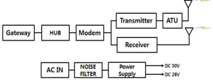
Table 1과 Fig. 1에서 제안한 변복조 시스템의 규격과 구조도를 각각 보여준다. 변복조 시스템의 점유 대역폭은 약 3 kHz이며, 최대 전송 속도는 약 3.6 kbps이다. 직교주파수 분할다중 (OFDM) 기술 을 사용하여 부반송파를 통해서 송신되는 심볼의 전송 주기를 길게 한다. OFDM을 위한 부반송파의 개수는 32이다 [2].
Data frame은 36 byte로 구성이 된다. 각 부반송 파의 정보의 위치를 알려주는 sequence number가 2 byte씩 2개이다. Information은 28 byte를 전송하 고, CRC 오류 검출 코드가 마지막으로 전송된다.
OFDM 통신을 위해서 IFFT 출력에서 4개를 사 용하여 이를 주기적 전치 부호(cyclic prefix)로 사 용한다. 송신 데이터의 샘플링 속도는 약 2.67 ksps 이고, 부반송파 사이의 주파수 이격은 약 83 Hz이다.
각 부반송파는 차동 사분위상 천이변조(DQPSK)를 이용한다. 한편, 오류 검출을 위해서 CRC code를 사용한다. 변조기는 DQPSK 변조, IFFT, cyclic prefix 추가 등으로 구성된다. 복조기는 심볼 타이밍 검출, 주파수 오프셋 추정 및 보상, FFT, differential decoding 등으로 구성된다. 본 시스템에서는 DAC 와 ADC 기능을 음성 코덱 IC를 이용하여 구현한 다. 코덱의 샘플링 속도와 분해능은 각각 8 ksps와
24 bit이다. 디지털 변복조에서는 이중에서 14 bit 의 데이터를 이용한다. 송신기에서의 신호 발생은 모뎀에서 변조되는 baseband 신호는 첫번째 IF 주 파수와 믹싱되고, pass band가 20KHz인 x-tal 필 터를 거쳐 두 번째 IF 주파수와 다시 한번 믹싱되 어 최종적으로 RF 신호를 송신 할 수 있다. 수신기 는 송신기와 반대순으로 동작하여 복조된 신호를 수신할 수 있다.
그림 2는 디지털 변복조부의 구조를 보여준다. 디 지털 변복조부는 FPGA를 통해서 하드웨어로 구현 하였다. Xilinx사의 zynq-7000 programmable SoC 를 사용하였다. 데이터 패킷은 프리앰블과 데이터 payload로 구성된다. 프리앰블은 2 OFDM symbol 이 사용된다. 첫 번째 OFDM 심볼은 신호 검출을 위해서 사용된다. 두 번째 OFDM 심볼은 부반송파 별 DQPSK의 differential decoding을 위한 최초 데 이터로 사용된다. 한편, 데이터 보안을 위해서 송신 데이터는 스크램블링 된다. 그림 3은 변조부 LPF 의 임펄스 응답을 보여준다. 그림 4는 디지털 변복 조부 모듈을 보여준다. RF 송신국은 1kw 송신기 (여진기, 전력증폭기, 전원공급기, 하모닉필터), 수신 기, 기준클럭발생기, 게이트웨이로 구성되어 있다.
Parameters Specification
Data rate 3.6 kbps
Bandwidth about 3 kHz
FFT size 32
Extension length 4
Sampling rate 2.67 ksps
Subcarrier frequency spacing 83 Hz
Modulation DQPSK
Error correction code CRC
표 1. 제안 시스템 규격
Fig. 1. Block diagram of proposed system.
그림 1. 제안 시스템의 구조도
Fig. 3. Impulse response of transmitter FIR LPF.
그림 3. 변조부 LPF의 임펄스 응답
Fig. 4. Digital MODEM module.
그림 4. 디지털 변복조 신호처리 모듈
Fig. 5. Digital HF Shore station transmitter.
그림 5. 디지털 HF 해안국용 통신시스템 송신국
Fig. 6. Digital HF Shore station receiver.
그림 6. 디지털 HF 해안국용 통신시스템 수신국
Bit-to-symbol Mapping (DQPSK)
Scrambling 32-point
IFFT
Cyclic Prefix insertion
Parallel- to- Serial conversion
FIR LPF (inter- polation)
Up-
conversion DAC
FIR LPF Down-
conversion Decimator
Timing Synchro-
nization
32-point FFT
Differential decoding ADC
Pilot insertion
ADC
Frequency Offset compensation
Frequency Offset estimation
Descram- bling
Fig. 2. Block diagram of digital modem.
그림 2. 디지털 변복조부의 구조도
Ⅲ. 시스템 개발
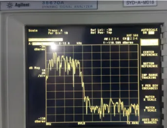
그림 5와 그림 6은 개발된 장비를 보여준다. 디지 털 HF 해안국용 통신 시스템은 송신국과 수신국으 로 구성되어진다. 송신국은 외부 신호를 입력 받아 데이터 신호로 변조하여 RF 신호를 송신하는 장치 이다. 수신기는 RF 신호를 수신하여 복조시키는 장비이다. 그림 7은 변조 신호의 스펙트럼 측정 결 과를 보여준다. 표1에서 제안한 규격과 같이 대역 폭이 약 3 kHz 임을 알 수 있다. 그리고, 신호 대역 이외의 대역에서는 50 dB 이상 신호가 제거됨을 알 수 있다.
Fig. 7. Measured spectrum of modulated signal.
그림 7. 변보 신호의 스펙트럼 측정 결과
그림 8은 수신부 실험 결과를 보여준다. FPGA로 구현된 복조부 내부 신호를 로직 분석기로 측정한 결과이다. OFDM 신호를 수신하면서 복조부의 state 천이가 정확하게 이루어진다는 것을 확인할 수 있다.
Ⅳ. 결론
본 논문은 디지털 해상 통신 서비스를 지원하기 위해서 ITU-R M.1798-1 표준을 기반으로 한 OFDM 기반의 HF 대역 디지털 해상 이동 통신 시스템을 제안, 개발하였다. 전체 시스템은 송신국 장비와 수 신국 장비로 구성이 된다. 디지털 변복조부는 FPGA를 이용하여 구현하였다. 하드웨어 실험을 통해서 송신국과 수신국 장비의 기능을 검증하였 다. 제안된 시스템은 국내 선박의 근해 및 원양 어 업을 위한 통신 장비로 할용될 것으로 기대된다.
References
[1] R. Prasad, OFDM for Wirelesss Communications
Systems, Artech House, 2004.
[2] Characteristics of HF radio equipment for
the exchange of digital data and electronic mail in the maritime mobile service, ITU-R M.1798-1,
2010.[3] J. C. Choi, “A Plan on the Digitalize of Fig. 8. Logic analyzer measurement result of digital demodulator.
그림 8. 디지털 복조부의 로직분석기 측정 결과
Maritime Communication using HF band in Domestic,” The Journal of the Korea Institute of
Maritime Information & Communication Sciences,
vol.8, no.6, pp.774-781, 2004.[4] S. H. Jung, G. S. Yang, G. R. Jeong, D. K. Park, and J. C. Kim, “The improvement of maritime data communication systems for e-Navigation,”
Journal of advanced navigation technology, vol.15,
no.8, pp.939-945, 2011.[5] Y. Y. Choo and D. U. Jung, “HF Data Communication Service Using SSB Modems for Maritime Applications,” Journal of the Korea
Institute of Information and Communication Engineering, vol.15, no.12, pp.2449-2554, 2011.
DOI:10.6109/jkiice.2011.15.12.2549
[6] Report of the Correspondence Group on the
draft of the Modernization Plan of the GMDSS,
IMO NCSR 4/12.[7] S. Valčić, Z. Mrak, and D. Kezić, “Comparison of new technologies for data exchange in the maritime HF frequency band,” in
Proc. of International Conference on Information &
Communication Technology Electronics &
Microelectronics, 2013, pp.498-502.
[8] H. Shin, “A Study on the Development Direction in Korea Marine Communication,” Journal of the
Korea Institute of electronic communication sciences,
vol.8, no.4, pp.527-534, 2013.DOI:10.13067/JKIECS.2013.8.4.527
[9] G. Kim, J. Choi, J. Yang, S. Choi, and J.
Choo, “A Study on the Economic Value Valuation for maritime communications frequencies,” in Proc.
of Korea Institute of Communications and Information Sciences Fall Conference, 2013, pp.339-342.
[10] P. Bergada, R. M. Alsina-Pages, J. L. Pijoan, M. Salvador, J. R. Regue, D. Badia, and S.
Graells, “Digital transmission techniques for a long haul HF link: DSSS versus OFDM,” Radio
Science, vol.49, no.7, pp.518-530, 2014.
DOI:10.1002/2013RS005203
BIOGRAPHY
Sung-Cheol Choi (Member)
1998:BS degree in Electronics and Communications Engineering.
1998~:Research Engineer, SAMYUNG ENC Co., Ltd.
Jeong-Nyun Kim (Member)
1997:BS degree in Marine Electronic Communications Engineering, Mokpo National Maritime University.
1999:MS degree in Electronics and Communications Engineering, Korea Maritime and Ocean University.
2007:PhD degree in Marine Electronic Communications Engineering, Mokpo National Maritime University.
1998~:Fishery Info-Communication System, National Federation of Fisheries Cooperatives.
Hyung Chul Park (Member)
1996:BS degree in Electrical Engineering, KAIST.
1998:MS degree in Electrical Engineering, KAIST.
2003:PhD degree in Electrical Engineering, KAIST.
2003~2005:Research Engineer, Hynix Semiconductor.
2005~2010:Assistant Professor, Hanbat National University
2010~:Professor, Seoul National University of Science and Technology