Ⅰ. 서 론
총의치 치료의 목적은 완전 무치악 환자의 심미 및 기능 회복에 있다. 상실된 치아와 치조골이 의치상 과 인공치로 대치됨으로써 의치환자는 비교적 양호 한 심미적 결과를 얻을 수 있으나, 잔존 치조제로부 터 지지를 받고 있는 의치는 기능적 측면에서 만족 스러운 저작효율과 저작압을 제공하지는 못한다.1-6) 이러한 기능적 문제의 주원인은 감소된 안정성과 유 지력 그리고 하중지지능력 때문이다.7)
완전 무치악 환자의 구강기능을 증진시키기 위한 임플란트 치료는 크게 fixed-detachable bridge와 같 은 고정성 보철물과 overdenture와 같은 가철성 보철 물로 구분할 수 있다. 임플란트에 의해 지지를 받는 고정성 보철물은 1965년 Bra�nemark에 의해 처음으 로 시술된 이래 많은 장기간의 임상보고8-11)와 생체역 학적 연구12)를 통하여 효율성과 안정성이 입증되고 있다. 이러한 고정성 보철물은 심리적으로 안정감을 주고 저작기능을 크게 개선시키며 치조점막의 문제 도 적게 유발하는 장점이 있으나, 심미성이 나쁘고 발음에 문제를 일으키며 구강위생 유지가 어려울 뿐 만 아니라 비교적 많은 수의 임플란트를 식립할 수 있는 충분한 잔존골이 있어야 한다는 단점이 있다.13) 한편 임플란트와 잔존치조제에 의해 지지되는 가 철성 보철물을 이용한 치료술식은 고정성 보철물 첫 시술 후 약 20년이 지나서야 보고되기 시작하였는데
14-16), 임플란트를 이용한 가철성 보철물을 장착한 환
자는 의치의 안정성과 하중지지능력 향상으로 총의
치 환자에 비하여 저작력이 증가되며17), 의치에 대한 만족감이 향상되고 더 다양한 음식을 저작할 수 있 으며 또한 일상생활 중에 의치로 인한 문제를 더 적 게 경험하는 것으로 보고되고 있다.18) 비록 가철성 보철물은 가철성이라 심리적 거부감과 교합력을 지 지하는 후방 잔존 치조제의 지속적인 흡수로 인한 재이장의 번거로움과 같은 문제점을 갖고 있으나, 심한 잔존 치조제 흡수, 불량한 악간관계, 높은 심미 적 욕구 또는 예상되는 발음상의 문제를 갖고 있는 무치악 환자의 치료에 효과적이며, 특히 고정성 보 철물을 지지할 만큼 충분한 수의 임플란트를 식립하 지 못할 경우 주적응증이 된다.13,19)
잔존 치조제 흡수가 어느 정도 진행된 하악 무치악 환자에서 해부학적 또는 경제적 이유로 악골의 전방 부 양측이공사이에 한정하여 네 개 정도의 임플란트 만을 식립할 수 밖에 없는 경우가 많다. 이러한 경우 임상적 상황에 따라 후방 cantilever를 가진 고정성 보철물로 수복하는 방법이 가능할 수도 있으나20), 심 미성과 구강위생은 물론 생역학적 측면에서 가철성 보철물인 overdenture가 우선적으로 고려될 수 있다.
이러한 임상적 판단은 overdenture의 경우 잔존 치조 제가 지지를 일부 담당하고 있기 때문에 임플란트로 전달되는 부하가 감소될 것이라는 일반적인 가정에 근거하고 있다. 그러나 Jemt 등21)은 상악 무치악에 여섯 개의 임플란트를 식립한 환자에서 고정성 보철 물보다 overdenture 장착 시 최후방 지대원주에 가해 지는 압축력/인장력은 작았으나 상대적으로 더 높은 굽힘 모멘트가 발생하였음을 보고한 바 있다.
대한치과보철학회지:Vol. 40, No. 5, 2002
하악 임플란트 overdenture에서 anchorage system이 하중전달에 미치는 영향
부산대학교 치과대학 보철학교실 김진열∙전영찬∙정창모
하악 임플란트 overdentures에 관한 장기간의 연구 는 드물며, 보고자에 따라 다양한 관찰기간에서 임 플란트 성공률에 큰 차이를 보이고 있다(0%�24.4
%).19,22-30) Jemt 등31), Hutton 등27), Johns 등32), Engquist 등19), Lekholm 등33)그리고 Goodacre 등34) 은 overdenture의 임플란트 실패율이 상악에서 높고 하악에서 낮으며 골질과 골량이 치료예후를 결정하 는 매우 중요한 인자라고 보고하였다. 한편 Naert 등
24)은 하악 overdenture에서 일어나는 합병증은 골유 착 술식과는 크게 관계가 없고 overdenture 보철술식 에 직접적으로 연관되어 있으며, 임플란트 식립위 치, anchorage system의 선택, 하부구조물의 적합도, 교합 그리고 구강위생이 overdenture의 성공에 영향 을 미치는 중요한 보철적 요인이라고 강조하였다.
임플란트로부터 지지 또는 유지력을 얻는 over- denture에서 anchorage system 즉, 상부 및 하부 구 조물의 설계와 attachment의 선택은 의치의 안정성 과 유지력 그리고 임플란트 지지골로의 기능하중 전 달에 영향을 미치며, 매식체의 수와 위치, 골의 양과 질, 그리고 환자의 요구 등에 따라 달라져야 한다.
부적절한 anchorage system으로 인한 과부하는 보철 물의 파절23,25,29,30,32,35-39)
이나 abutment screw의 풀림
23,26,35,38)과 파절23,36,37)그리고 gold screw의 풀림23,35)과 파절23,26,39), attachment의 잦은 망실26,30,32,35,40,38,41,39)
은 물론 임플란트 경부주위의 변연골 흡수23,32,42)나 미세 골절로 인한 골유착의 상실43,44)을 야기하며 나아가 매식체의 파절36)을 야기할 수 있다. 따라서 anchor- age system의 설계와 선택은 술자의 임상 경험이나 선호도보다는 생체역학적 연구나 장기간의 임상연 구를 통한 과학적 논리에 근거하여 결정되어야 할 것이다.
과거 광탄성 응력분석43,45-48), 유한요소 응력분석49-51) 또는 스트레인 게이지52-54)를 이용하여 하악 임플란트 overdenture의 anchorage system이 응력분포에 미치는 영향을 비교 검토한 다수의 연구가 보고된 바 있다. 그러나 현재까지 보고된 대다수의 연구
43,45,47,49,50,52-54)는 주로 두 개의 임플란트를 이용한
overdenture에 관한 것이며, 다수의 임플란트를 이용 한 overdenture에서 anchorage system이 하중 전달 에 미치는 영향에 관한 연구는 매우 희박한 실정이 다.
이에 본 연구에서는 양측 이공사이에 식립된 네 개
의 임플란트를 이용한 하악 bar overdenture에서 anchorage system이 하중전달에 미치는 영향을 삼차 원 광탄성 응력분석법을 이용하여 알아보고, 그 응 력분포 양상을 고정성 보철물과 상호 비교하여 보고 자 하였다.
Ⅱ. 연구재료 및 방법 1. 하악골복제모형 제작 및 임플란트 식립
사체의 무치악 하악골을 공업용 실리콘(KE1402, Shin-Etsu Chemical Co., Japan)으로 인상을 채득 하여 에폭시 레진(JRA-323, Jeungdo Chemical Co. Korea) 모형을 제작한 후, 하중 이 가해질 때 모 형의 안정성을 위하여 가로 9.5cm, 세로 6cm, 높이 1cm의 기저부를 형성 하였다. 레진 모형의 치조정을 임플란트 식립이 용이하도록 평탄하게 연마하고 양 측 이공 전방에 직경 4mm, 길이 15mm의 나사형 AVANA임플란트(AF1B026, Osstem Implant Co.
Korea) 네 개를 좌우 대칭으로 중심간 거리가 13mm 가 되도록 같은 높이로 평행하게 식립 한 후, 점막 조직의 재현을 위하여 2mm 두께의 baseplate wax를 잔존 치조제상에 이장하였다.
2. 보철물 제작
(가) 작업모형 제작 및 인공치아 배열
임플란트에 square impression coping(ICFR500, Osstem Implant Co. Korea)을 연결하고 실리콘 인 상(Examix NDS, GC Co., Japan)을 채득한 다음, 기공용 아날로그를 연결하고 초경석고(Fujirock, GC Co., Japan)를 부어 보철물 제작을 위한 작업모 형을 완성하였다.
레진 기록상과 왁스 교합제를 제작하고 반조절성 교합기에 작업모형을 부착한 후 중절치에서 제 2 대 구치까지 레진치(Endura artificial teeth, Shofu Co., Japan)를 배열하였다. 다음 재부착용 jig를 교합 기 상체에 고정시키고 레진치 교합면의 석고 index 를 채득하여, 이 index를 bar 구조물의 납형제작과 실험의치의 레진치 배열에 각각 이용하였다.
(나) Bar 구조물의 제작
모형의 기공용 아날로그에 non-hexed gold UCLA abutment(GCR100, AVANA implant system, Osstem Implant Co. Korea)를 연결한 후, 다음과 같이 attachment의 종류, 후방 cantilever 유무 그 리고 bar 측면의 milling 유무에 따라 서로 다른 다 섯가지 bar 구조물의 납형들과 추가적으로 후방 cantilever를 가진 고정성 보철물의 납형을 제작하였 다. 완성된 납형들을 매몰한 후 제 4 형 금합금 (Super 45, Soo min dental alloy Co. Korea)으로 주조하고 연마하였다.
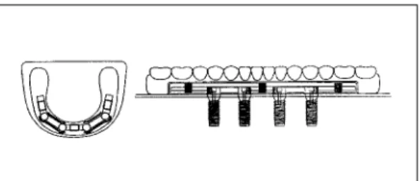
1) 제 1 형 : Hader bar using clips(no cantilever).
4mm 높이의 Hader bar(Preci line Co., Swiss)를 치은에서 상방으로 0.5mm 떨어지도록 gold UCLA abutment사이에 연결하였다(Fig. 1). 후방 can- tilever는 없으며, 세 개의 플라스틱 clip이 각 Hader bar의 중앙에 위치되도록 하였다.
2) 제 2 형 : Cantilevered Hader bar using clips.
제 1 형과 같이 Hader bar를 gold UCLA abutment 사이에 연결하고, 추가적으로 13mm 길이의 후방 cantilevered Hader bar를 부착하였다(Fig. 2). 세 개 의 플라스틱 clip이 정중부와 양측 cantilevered bar
Fig. 1. Anchorage system of type 1. Fig. 2. Anchorage system of type 2.
Fig. 3. Anchorage system of type 3.
Bold lines in left drawing indicate the intimate con- tacts between milled bar and metal framework.
Fig. 4. Anchorage system of type 4.
Bold lines in left drawing indicate the intimate con- tacts beween milled bar and metal framework.
Fig. 5. Anchorage system of type 5. Fig. 6. Prosthetic design of type 6.
의 중앙에 위치되도록 하였다.
3) 제 3 형 : Cantilevered Hader bar with milled surface using clips.
제 2 형과 같은 bar 구조물의 납형을 형성한 후, 양 측 전, 후방 임플란트 사이의 bar에 주조용 왁스를 추가하고 milling하여 상단의 두께가 2mm이고 2�의 경사도를 갖는 tapered milled bar를 제작하였다 (Fig. 3). 세 개의 플라스틱 clip이 제 2 형과 같이 정 중부와 양측 cantilevered bar의 중앙에 위치되도록 하였다.
4) 제 4 형 : Cantilevered milled-bar using swivel-latchs and frictional pins.
13mm의 후방 cantilever를 갖고 상단의 두께가 2mm이며 2�의 경사도를 갖는 tapered milled bar를 제작하였다(Fig. 4). 이 anchorage system은 전방 순 측에 두 개의 frictional pin과 양측 후방 cantilevered bar의 중앙 설측에 두 개의 swivel-latch mini attachment(SAE dental vertriebs GmBH- International, Germany)가 위치되도록 설계되었다.
5) 제 5 형 : Hader bar using clip and extracoronal universal hinge resilient attachments(ERA).
Hader bar를 gold UCLA abutment사이에 연결하 고 bar 구조물의 양측 후방으로 ERA의 matrix(APM Stern Gold Co., USA)를 부착하였다(Fig. 5). 이 anchorage system은 정중부에 한 개의 플라스틱 clip과 양측 후방에 두 개의 ERA가 위치되도록 설계 하였다.
6) 제 6 형 : Cantilevered fixed-detachable prosthesis.
제 2 대구치까지 연장된 cantilever를 갖는 고정성 임플란트 보철물의 금속 구조물을 제작하였다(Fig.
6).
(다) 실험의치 제작
제 3 형과 4 형과 같이 tapered milled bar가 설계 된 경우에는 의치상과 milled bar 사이의 긴밀한 접 촉을 얻기 위하여 의치상 내부용 금속 구조물을 제 작하였다(Fig. 3과 4). 그리고 제 4형에서는 의치제 작 전에 완성된 금속 구조물을 bar 구조물에 위치시
키고 치과용 방전가공기인 SAE-2000(SAE dental vertriebs GmBH-International, Germany)에서 swivel-latch attachment와 frictional pin의 recep- tacle을 형성한 후 swivel-latch attachment와 0.9mm pin을 금속 구조물에 고정하였다.
Bar 구조물 또는 bar 구조물과 금속 구조물을 작업 모형에 위치시킨 후, 정해진 위치에 플라스틱 clip이 나 ERA의 기공용 아날로그를 삽입하고 undercut부 위를 block out하였다. 레진치를 교합면 석고 index에 재위치시키고 왁스로 의치상을 형성한 후, 통법에 따라 매몰하여 열중합형 의치상용 레진(Acron MC, GC dental industrial Co., Japan)을 전입, 온성하 고 연마하였다.
점막조직의 재현을 위하여 임플란트가 식립된 악 골복제모형으로부터 이장된 왁스를 제거한 다음 bar 구조물을 abutment screw로 고정하고, 후방연장 의치상 하부에 접착제를 도포한 후 light body의 실 리콘 인상재(Examix NDS, GC Co., Japan)를 이장 하고 의치를 bar 구조물에 완전히 안착시켰다. 인상 재 경화 후 의치를 철거하고 잉여 인상재를 제거한 다음 각 실험의치의 기공용 아날로그들을 환자용 플 라스틱 clip이나 흰색의 ERA patrix로 교환하였다.
고정성 임플란트 보철물 역시 위와 같은 방법으로 레진치를 위치시키고, 왁스로 치은부위를 형성한 후 매몰, 온성하였다.
3. 광탄성 모형 제작
악골복제모형에 bar 구조물 또는 고정성 보철물을 abutment screw로 고정하고 공업용 실리콘으로 인 상채득하여 주형을 제작하였다. 다음 임플란트 매식 체를 bar 구조물 또는 고정성 보철물에 abutment screw로 연결하고 주형에 재위치시킨 후, Araldite D-type 에폭시 레진(CY230, Nagase CIBA Geigy Co., Japan)과 경화제(HY951, Nagase CIBA Geigy Co., Japan)를 10 : 0.8 의 비율로 혼합하여 주입하고 중합시켜 광탄성 모형을 제작하였다. 완성 된 광탄성모형을 투과형 광탄성 실험장치(PA-420, Riken Keiki Fine Instrument Co., Japan)에서 잔 류응력 유무를 검사하고 잔류응력이 발생하지 않은 것을 확인한 후 다음 과정을 진행하였다.
4. 하중조건과 응력동결
보철물이 장착된 광탄성 모형을 응력동결로(PA- 2S, Riken Keiki Fine Instrument Co., Japan)에 넣고 좌측 제 1 대구치의 중심와에 4Kg의 수직하중 을 가한 후 응력동결주기에 따라 응력을 동결시켰다.
5. 무늬차수 계측과 비교
응력동결이 끝난 광탄성 모형을 α-Bromonap- hthalene 과 유동파라핀 혼합액에 침전시킨 후 투과 형 광탄성 실험장치에서 임플란트 지지골과 후방 의 치상 하부 잔존 치조제에 나타난 전체적인 응력 분 포를 관찰하고 사진 촬영하였다. 다음 임플란트를 중심으로 약 15mm정도의 두께가 되도록 순설 방향 으로 광탄성모형을 절단하고 사포로 활택하게 연마 한 후, 각 절단모형에서 임플란트의 근원심과 순설 측 지지골을 따라 선정한 측정 기준점의 무늬차수와 하중측 임플란트 후방 잔존 치조제에 나타난 무늬차 수를 Null-balance Compensator (Measurement Group, Photoelastic div., Vishay Co., USA)를 이 용하여 계측하고, 압축과 인장응력을 구분한 다음 사진 촬영을 하였다.
Ⅲ. 연구성적
실험결과 모형간의 응력분포 비교를 용이하게 하 기 위하여 우측 최후방 임플란트를 1번 임플란트로 하여 좌측 최후방 임플란트까지 4번 임플란트라 명 하고, 임플란트마다 근원심과 순설측 지지골의 측정 기준점에 발생한 무늬차수 중 각각의 최고 무늬차수 를 압축(-)과 인장(+)으로 구분하여 사진 1에서 사 진 6까지 나타내었으며, Table Ⅰ에는 모든 모형에서 응력집중이 가장 크게 일어난 하중측 최후방 임플란 트 지지골과 후방 치조제에 나타난 최고무늬차수를 비교 요약하였다.
1. 제 1 형 : Hader bar using clips(no cantilever).
2번, 3번, 4번 임플란트에서는 근단부에 압축성분 의 최고응력이 나타났으며, 순설측보다는 근원심으 로의 응력집중이 더 컸다. 한편 하중점 반대측 1번
임플란트에 나타난 최고응력은 인장성분으로 순설 측으로 더 높았다(사진 1. c과 사진 1. d). 하중점에 인접한 4번 임플란트에 가장 높은 5.0차의 최고무늬 차수가 나타났으며 다음으로 3번, 2번, 1번 임플란트 순으로 감소하였다. 하중점 하방의 잔존 치조제에 압축성분의 응력집중이 나타났으며, 최고무늬차수는 5.5차로써 overdenture를 위한 anchorage system 중 가장 작은 값을 보였다(Table Ⅰ, 사진 1. b).
2. 제 2 형 : Cantilevered Hader bar using clips.
이 모형 역시 2번, 3번, 4번 임플란트에 나타난 최 고응력은 압축응력이었으며 1번 임플란트에 나타난 최고응력은 인장응력 이었으나, 제 1 형 anchorage system을 이용한 모형에 비하여 4번과 1번 임플란트 의 근단부에 1차수 이상 더 높은 최고응력이 관찰되 었다(사진 2. c와 사진 2. d, Fig. 10). 가장 응력이 집 중된 4번 임플란트의 최고무늬차수는 6.3차였으며, 후방 잔존 치조제에는 7.0차의 최고무늬차수가 나타 났다(Table Ⅰ, 사진 2. b).
3. 제 3 형 : Cantilevered Hader bar with milled surface using clips.
이 모형에서도 2번, 3번, 4번 임플란트에 나타난 Table Ⅰ. Maximum stress transfer to ipsilateral dis- tal implant and supporting ridge
Type 1 5.0 5.5
Type 2 6.3 7.0
Type 3 6.3 7.0
Type 4 5.6 7.0
Type 5 3.5 6.0
Type 6 18.3 0.0
* Type 1 = Hader bar using clips(no cantilever);
Type 2 = Cantilevered Hader bar using clips;
Type 3 = Cantilevered Hader bar with milled sur- face using clips; Type 4 = Cantilevered miiled-bar using swivel-latchs and frictional pins; Type 5 = Hader bar using clip and ERAs; Type 6 = Cantilevered fixed- detachable prosthesis.
Anchorage Number of fringes system * Implant Supporting ridge
최고응력은 압축응력이었으며, 1번 임플란트에 나타 난 최고응력은 인장응력 이었다. 제 2 형 anchorage system을 이용한 모형에 비하여 2번 임플란트를 제 외한 나머지 임플란트에서는 근원심보다 순설측의 최고응력이 더 높게 나타났으며, 4번 임플란트 근단 부의 근원심에 발생한 최고응력이 1.5차수 감소한 반면 1번 임플란트 순측 근단부에 0.8차수 더 높은 최고 응력이 관찰되었다(사진 3. c와 사진 3. d). 가 장 높은 최고무늬차수는 4번 임플란트 순설측 근단 부에 나타난 6.3차였으며, 후방 잔존 치조제에는 7.0 차의 최고무늬차수가 나타났다(Table Ⅰ, 사진 3. b).
4. 제 4 형 : Cantilevered milled-bar using swiv- el-latchs and frictional pins.
이 모형의 전체적인 응력분포는 제 3형 anchorage system을 이용한 모형과 매우 유사하였으나 2번 임 플란트 근원심 근단부에 최고응력이 0.5차 증가되고 4번 임플란트의 순설측과 1번 임플란트의 원심 및 순설측 근단부에 0.5차 이상 최고응력의 감소가 나 타났다(사진 4. c와 사진 4. d). 4번 임플란트 순설측 근단부에 5.6차의 가장 높은 최고무늬차수가 나타났 으며, 후방 잔존 치조제에 나타난 최고무늬차수는 7.0차였다(Table Ⅰ, 사진 4. b).
5. 제 5 형 : Hader bar using clip and ERAs.
이 모형에서도 2번, 3번, 4번 임플란트에는 압축성 분의 최고응력이, 1번 임플란트에는 인장성분의 최 고응력이 나타났으며 하중점에 인접한 4번 임플란트 에 가장 높은 최고응력이 집중되었다. 4번 임플란트 근원심 근단부에 나타난 3.5차의 최고무늬차수는 전 체 anchorage system 중 가장 낮았으며, 각 임플란트 간의 최고응력 차이도 가장 적은 균일한 응력분포 양상을 보였다(사진 5, Table Ⅰ). 하중점 하방 잔존 치조제에는 6.0차의 최고무늬차수가 관찰되었다.
6. 제 6 형 : Cantilevered fixed-detachable pros- thesis.
이 고정성 보철물 모형에 나타난 응력분포는 응력 의 크기나 분포양상에 있어 다른 overdenture 모형들
과 큰 차이를 보였다(사진 6. a). 각 임플란트에 나타 난 최고응력의 성분은 4번과 3번 임플란트에서는 압 축응력을, 2번 임플란트의 근원심으로 인장응력을 순설측으로는 압축응력을, 1번 임플란트에서는 인장 응력을 나타내었으며, 전체적으로 최고응력의 크기 가 크게 증가되어 가장 높은 최고무늬차수를 보인 4 번 임플란트 근원심측 근단부에는 18.3차의 매우 높 은 응력이 집중되었다(사진 6. c와 사진 6. d).
Ⅳ. 총괄 및 고안
광탄성 분석법은 악골의 불균질성과 비등방성을 모형화하는데 명백한 한계가 있으나, 복잡한 기하학 적 형태나 물리적, 기계적 성질을 갖고 있는 구조물 들을 직접 실험에 사용할 수 있기 때문에 임플란트 보철물과 같은 복잡한 구조물에 의해 지지골내 발생 하는 응력을 비교 분석하는데 유리하다.46,55-57)본 연 구에서는 3차원 광탄성 실험법을 이용하여 근원심뿐 만 아니라 순설측 임플란트 지지골에 발생하는 응력 분포상태를 보다 자세히 관찰하고자 하였다.
임플란트 overdenture에 사용되는 attachment는 각 임플란트를 상호 연결하여 splint효과를 기대하는 bar attachment와 독립적으로 사용되는 solitary attachment로 크게 구분할 수 있다. Bar attachment 는 우수한 유지력과 안정성을 제공12,58)하는 반면, 부 피가 커서 이물감을 주고 술식이 복잡하며 비용이 추가되는 단점이 있다.
하악 이공 사이에 임플란트를 식립하여 임플란트 overdenture치료를 시행할 경우 이러한 attach- ment의 선택뿐만 아니라 필요한 임플란트 개수에 대한 많은 논란이 있어 왔다. Mericske-Stern25)과 Van Steenberghe 등59)은 두 개의 임플란트만을 사용 하여도 attachment의 종류에 관계없이 임상적으로 우수한 결과를 얻을 수 있었다고 보고한 반면, Kirsch 등60)과 Schroeder 등61)은 overdenture의 안 정성을 증진시키고 임플란트의 과도한 하중을 피하 기 위하여 적어도 세 개 또는 네 개의 임플란트를 bar로 연 결 하 여 사 용 하 도 록 제 안 하 였 으 나 Hemmings 등26)과 Adell 등9)은 두 개, 세 개 또는 네 개의 임플란트에 의해 지지되는 overdenture에서 각 임플란트의 성공률은 무치악 고정성 보철물과 유 사하였다고 보고하였으며 나아가 Engquist 등19)과
Mericske-Stern25)는 두 개, 세 개 또는 네 개의 임플 란트 overdenture 사이에 임플란트 주위조직의 건강 상태에는 차이가 없었고 Engquist는 같은 연구에서 bar를 이용하여 임플란트를 연결할 필요는 없다고 주장하였다. 강과 방48)은 광탄성학적 응력분석을 이 용한 연구를 통해 임플란트의 수가 많을수록 응력분 산에 양호하나, 두 개 또는 세 개의 임플란트를 이용 한 경우에도 매식위치와 bar의 설계를 적절히 하면 양호한 응력분산 효과를 얻을 수 있을 것이라고 하 였다. 그러나 Meijer 등51)은 두 개와 네 개의 임플란 트를 사용한 경우를 유한요소분석으로 연구한 보고 에서 두 개 대신 네 개의 임플란트를 식립하고 bar로 연결하여도 응력은 감소하지 않았다고 하였다.
Batenburg 등62)은 하악 임플란트 overdenture에 관 한 약 40편의 보고를 고찰한 결과, 총의치 환자가 의 치 안정성과 저작능률의 향상을 원한다면 일반적으 로 bar로 연결된 두 개의 임플란트로 충분하지만, 잔 존골 높이가 12mm이하인 경우 혹은 악궁이 좁은 경 우 및 대합되는 상악이 자연치인 경우 그리고 점막 에 만성적으로 외상성 궤양을 호소하는 경우에 bar 로 연결된 네 개의 임플란트에 의해 지지되는 over- denture를 권장하였다. 또한 ball attachment는 치 조골의 흡수가 심한 경우에는 충분한 유지력을 제공 하지 못할 수가 있으며, 유지력이 소실된 경우 female retainer를 교체해야 하는 불편이 있다고 하였 다.
한편 Bra�nemark 등20)은 네 개와 여섯 개의 임플란 트를 이용한 고정성 보철물의 10년 후 임상보고를 통해 두 보철물간에 임플란트 성공률에 차이가 없었 음을 보고하면서 가능한 많은 임플란트를 식립하려 는 일부 임상가들의 최근 경향에 의문을 제기하였 다.
이와 같이 양측 이공 사이에 식립된 임플란트의 개 수, 하악골의 양과 질, 악궁의 형태 그리고 대합치 조건 등에 따라 보철물의 선택이나 설계가 달라질 수 있으나, 본 연구에서는 하악 무치악 환자를 가정 하여 네 개의 임플란트를 식립하고 bar로 연결할 경 우 임플란트에 가해지는 과부하를 예방할 수 있는 바람직한 anchorage system을 알아보고 또한 잔존 치조제로부터 일부 지지를 받고 있는 임플란트 overdenture가 고정성 임플란트 보철물에 비해 임플 란트 지지골에 발생하는 응력집중을 어느 정도 분산
시킬 수 있는 가를 비교 검토하여 보고자 하였다.
임플란트 overdentue 환자의 교합력에 대한 연구 에서 Mericske-Stern 등63)은 상악 임플란트 over- denture의 교합력이 50N�230N이였다고 하였으 며, Jemt 등64)도 역시 상악 임플란트 overdenture의 교합력을 48N�258N으로 보고하였고, Haraldson 등17)은 하악 임플란트 overdenture의 평균 저작력을 38.7N으로 최대 교합력을 131.5N으로 보고하였다.
본 실험에서는 4Kg의 수직하중을 가하였다. 하중 후 광탄성 모형의 응력 동결과정에서 에폭시 레진의 물성은 실온에 비해 40배 정도 연화된다.73) 이런 이 유로 예비실험과정 중 실제 교합력에 근접한 하중조 건에서는 광탄성 모형의 과도한 변형으로 인하여 의 도하지 않은 부위의 접촉이나 attachment의 이탈이 일어나는 것을 관찰할 수 있었다. 따라서 본 실험에 서는 여러번의 예비실험을 통하여 이러한 문제점을 야기하지 않으면서 등색선 무늬관찰이 가장 용이한 하중의 크기를 선택하였으며, 광탄성 모형의 탄성한 계 내에서는 응력의 크기는 하중에 비례하고 하중의 변화는 응력분포 양상에 큰 차이를 일으키지 않기 때문에 일정 하중조건 하에서 모형간 응력 비교에는 큰 문제가 없을 것으로 생각된다.
모든 광탄성 모형에서 하중측 후방 임플란트에 가 장 큰 응력이 집중되었으며 최고 무늬차수가 발생한 부위는 모두 임플란트 근단부였다. 실제 환자의 악 골은 피질골과 해면골로 이루어져 있으며 두 가지 골을 구분하여 설계한 광탄성65)또는 유한요소 실험
들49,50,66,67,72)에서는 골능 피질골에 응력집중이 가장
크게 일어나는 것으로 보고되고 있다. 그러나 본 실 험의 근단부 응력집중은 광탄성 모형이 한 가지의 레진으로 이루어져 있기 때문에 나타난 결과로써 비 록 실제 상황과는 응력분포 양상에 차이가 있을 것 으로 사료되나 전반적인 하중전달 양상과 모형간의 응력크기 비교에는 어느 정도 유용한 정보를 얻을 수 있을 것으로 생각된다.
대부분의 모형에서 압축응력의 크기는 4번, 3번 그리고 2번 임플란트순으로 감소되고, 비작업측 1번 임플란트에는 인장응력이 나타났는데 이러한 응력 분포의 양상은 악골모형이나 보철물의 설계, 실험 재료의 물성, 각 구조물 등의 연결 또는 결합조건, 하중점의 위치 등 연구 재료나 방법에 따라 달라질 수 있다.
임플란트 overdenture에서 교합력은 수직 근심 전 방 요소를 지니며 이 중 수직적 요소가 가장 우세하 다.68)이러한 교합력은 anchorage system을 통하여 임플란트 주위골로 전달되거나 일부는 잔존 치조제 로 전달되며, 잔존 치조제의 지지 정도는 anchorage system의 설계에 따라 달라진다. 따라서 임플란트 overdenture에서 anchorage system은 의치의 유지 와 안정뿐만 아니라 임플란트로 전달되는 과부하 예 방에 매우 중요한 역할을 한다.
본 연구결과 모든 overdenture 광탄성 모형에서 잔 존 치조제에 응력이 발생하는 것을 관찰 할 수 있었 으며, 후방 잔존 치조제의 지지가 없는 고정성 보철 물의 최후방 임플란트에 나타난 최고 무늬차수가 overdenture들의 경우보다 약 3�6 배정도 높게 나 타났다(Table 1). Zitzmann과 Scha¨rer69)는 두 개 이 하의 ball attachment나 ovoid형의 single bar-clip 을 이용할 경우에는 잔존치조제로부터 지지를 얻을 수 있으나, 본 연구와 같이 회전을 허용하지 않는 둘 이상의 bar가 이용될 경우에 overdenture는 임플란트 에서만 지지된다고 하였으나, Sadowsky 등46)은 cantilever bar가 있는 overdenture에서 잔존 치조제 의 지지가 임플란트 지지골에 집중되는 응력의 분산 에 중요한 역할을 한다고 보고하였다. 따라서 본 연 구결과와 Sadowsky 등46)의 보고를 고려해볼 때 임 플란트가 식립되지 않은 후방 무치악 부위가 존재한 다면 anchorage system에 관계없이 가능한 의치상을 후방으로 길게 연장하는 것이 응력분산에 바람직하 다고 생각되나, 이러한 잔존 치조제로부터의 지지 정도는 anchorage system 외에도 임플란트 식립 부위의 골질, 임플란트의 개수나 길이 또는 굵기, 임 플란트 상부구조물의 강성, 또는 잔존 치조제의 양 과 형태 등에 따라 달라질 수 있기 때문에69)추후 이 러한 요소들이 고려된 심도 깊은 연구가 필요하다.
후방 cantilever bar가 없는 제 1형에 비해 can- tilever bar가 있는 제 2, 3, 4형의 모형에서 최후방 임플란트에 발생한 최고 무늬차수가 증가하였는데 이러한 결과는 cantilever에 의한 굽힘 모멘트 발생과 cantilever bar의 설계로 인한 후방 의치상 지지면적 의 감소 때문이며(Table Ⅰ), 의치상 지지면적의 감 소는 잔존 치조제에 발생하는 응력 또한 증가시켰 다. Zitzmann과 Scha¨rer69)는 cantilever의 길이를 cantilever bar의 길이 보다는 최후방 임플란트에서
최후방 교합점까지의 길이로 정의하고 있으며, 임플 란트 사이에 attachment를 위치시킬 만한 공간이 없 는 경우를 제외하고는 cantilever상에 attachment를 위치시켜서는 안 된다고 주장하였다.
따라서 overdenture의 운동을 허용하지 않는 anchorage system에서는 가능한 cantilever bar의 길 이를 최소화하여 하중을 임플란트 사이로 전달시키 고 잔존 치조제로부터 더 많은 지지를 얻는 것이 응 력분산에 유리하다고 생각된다. 그러나 예비실험 중 제 1형 모형에서 하중이 커질수록 다른 모형에 비해 의치가 쉽게 탈락하는 것이 관찰되었는데 이는 제 1 형과 같이 clip들이 좁게 배치되어 있을 경우에는 잔 존 치조골 흡수로 의치상이 적절한 지지를 못 받게 되면 의치의 유지력과 안정성이 크게 저하되고 플라 스틱 clip의 파손이 빨리 일어날 가능성이 높다는 것 을 의미한다. 따라서 제 1형의 경우 잔조 치조제 변 화에 따른 적절한 의치의 유지관리가 중요하며, 플 라스틱 clip 부위를 제외한 bar의 측면을 제 3형과 같 이 milling하고 의치상에 금속구조물을 사용하여 수 평력이나 모멘트에 대한 의치의 저항성을 높이는 방 법을 고려해야 할 것으로 생각한다.
Cantilever bar가 있는 제 2 형과 3 형에서 전체적 인 응력분포 양상은 서로 유사하나 제 3 형의 하중측 후방 임플란트에 발생하는 최고무늬차수가 제 2 형 에 비해 순설측으로는 차이가 없으나 근원심으로 1.5차수 감소하고 반대측 1번 임플란트의 순설측으 로 인장응력이 0.8차수 증가되어 나타났다. 이러한 결과는 두 anchorage system 모두 하중은 플라스틱 clip들에 의해 임플란트로 전달되지만, 플라스틱 clip들이 전적으로 유지, 안정 그리고 지지를 담당하 는 제 2 형에 비해 위에서 언급한 것처럼 제 3 형에 서는 milling된 bar의 측면과 의치상 금속구조물의 긴밀히 접촉이 의치의 안정성과 모멘트 저항에 일부 기여했기 때문으로 생각한다.
이처럼 milling된 bar와 의치내 금속구조물의 사용 은 하중 분산에 유리하고 의치의 유지력과 안정성의 증가에 기여하며 또한 attachment의 파손이 감소될 뿐만 아니라 attachment의 주기적인 교환이 용이하 고 의치의 파절 가능성이 감소하며 이물감이 적고 청결유지가 용이하다는 장점을 갖고 있으나 시간과 비용이 많이 든다는 단점을 갖고 있다. Davodi 등70) 은 이러한 anchorage system을 갖는 overdenture는
부가적인 유지력과 안정성을 제공할 뿐만 아니라 강 성이 크고 임플란트간의 연결고정효과가 우수하기 때문에 생역학적으로 유리하다고 하였으며, 기능성 은 고정성 임플란트 보철물과 유사하고 또한 플라스 틱 clip의 마모가 현저히 감소되어 보철물의 유지관 리를 최소화할 수 있다고 하였다.
한편 milling 된 bar와 swivel-latch 및 frictional pins 을 이용한 제 4 형은 같은 길이의 cantilever bar가 달 린 제 2 형과 제 3 형보다 더 우수한 응력분포를 양 상을 보였다. 이러한 결과는 비록 잔존 치조제의 지 지는 유사하다 하더라도 하중전달이 제 2 형과 제 3 형에서는 주로 플라스틱 clip을 통하여 이루어지는 반면 제 4 형에서는 의치의 금속구조물과 milling된 bar의 상단면의 접촉을 통하여 좀더 넓게 분산되어 일어나고, 전체적인 bar의 측면과 금속구조물의 접 촉은 제 3 형보다 더 확실한 의치 안정성과 모멘트 저항성을 제공하며, 또한 증가된 bar의 두께로 인하 여 임플란트간의 연결고정효과가 향상되어 나타난 결과71)로 생각된다.
제 3 형과 제 4 형에서는 제 2 형과는 달리 대부분 순설측 응력이 근원심 응력보다 크게 나타났는데 이 러한 이유는, 하중점인 제 1 대구치 중심와는 전방에 있는 임플란트들보다 약간 협측에 위치하는데 제 3 형과 제 4 형에 설계된 milled bar와 금속구조물에 의한 하중 지지효과가 좋아서 나타난 결과로 생각한 다.
플라스틱 clip과 ERA를 이용한 제 5 형에서는 전 체 모형 중 후방 임플란트에 집중된 응력의 크기가 가장 작고 또한 각 임플란트 간의 응력차이도 가장 적은 양호한 응력분포 양상을 나타내었다. 이는 정 중부 clip의 회전운동과 후방 ERA의 0.4mm의 수직 운동 허용에 의한 결과로써, 의치의 운동을 허용함 으로써 잔존 치조제에 응력이 증가할 것이라는 예상 과는 달리 cantilever bar가 달린 제 2, 3, 4 형들에 비 해 제 1 형과 마찬가지로 후방의치상 지지면적의 증 가로 잔존 치조제에 발생하는 응력의 크기 또한 작 았다(Table Ⅰ). 따라서 식립된 임플란트의 조건이 불리할수록 resilient type의 attachment를 사용하는 것이 임플란트나 잔존 치조제에 발생하는 응력을 분 산시킬 수 있는 바람직한 방법이라고 생각된다.
ERA를 이용한 overdenture 환자에서 장기간의 잔존 치조제 흡수에 따른 의치의 침하로 attach-
ment의 본래 운동기능이 상실된다. 이러한 문제를 예방하기 위하여 주기적인 의치관리가 필요하지만 이론적으로 ERA는 cantlever bar에 비하여 길이가 짧고 부착위치가 치조정에 가깝기 때문에 임플란트 에 가해지는 위해한 힘이 더 작을 것으로 예상되며 이에 관한 추가적인 연구가 필요하다.
고정성 보철물인 제 6 형은 전체적으로 overden- ture 모형들과 다른 응력분포 양상을 보였으며 하중 측 후방 임플란트에 응력이 매우 높게 집중되었다.
비록 임상연구20)를 통하여 네 개의 임플란트를 이용 한 하악 고정성 임플란트 보철물의 임상적 안전성은 입증되었다고는 하나 본 연구결과는 치료계획 시 잔 존 치조제의 지지를 받지 못하는 고정성 임플란트 보철물의 선택에 세심한 주의가 필요하다는 것을 시 사하고 있다고 생각한다.
본 연구에서 이용된 광탄성 응력 분석법은 피질골 과 해면골로 이루어진 복합적인 악골구조와 하악골 의 생리적 현상 등 실제와 유사한 실험모형이나 조 건을 재현하지 못한 한계성을 갖고 있다. 따라서 본 실험결과는 한정된 실험조건하에서 임플란트 over- denture를 위한 anchorage system이 하중전달에 미 치는 영향을 개략적으로 파악하고 상호비교한 것으 로만 해석되어야 할 것이다.
V. 결 론
양측 이공사이에 식립된 네 개의 임플란트를 이용 한 하악 임플란트 overdenture를 제작할 경우 anchorage system이 하중전달에 미치는 영향을 알아 보기 위하여 제 1 대구치 편측 하중시, 여러 가지 anchorage system 사용에 따른 임플란트 지지골내 응력분포 양상을 삼차원 광탄성 응력분석법으로 연 구 비교하였다.
본 연구에서는 다섯 가지 상이한 anchorage sys- tem을 갖는 overdenture들(제 1 형: Hader bar with- out cantilever using clips, 제 2 형: cantilevered Hader bar using clips, 제 3 형: cantilevered Hader bar with milled surface using clips, 제 4 형:
cantilevered milled-bar using swivel-latchs and frictional pins, 제 5 형: Hader bar using clip and ERA attachments)과 고정성 임플란트 보철물(제 6 형: cantilevered fixed-detachable prosthesis)을 포
함하여 총 여섯 개의 광탄성 모형을 제작하였다.
이상의 연구조건으로부터 다음과 같은 결론을 얻 었다.
1. 모든 모형에서 하중측 후방 임플란트 지지골에 가장 높은 응력이 집중되었다.
2. 하중측 후방 임플란트 지지골에 발생한 최고무늬 차수의 크기는 제 5 형, 제 1 형, 제 4 형, 다음으 로 제 2 형 및 제 3 형, 그리고 제 6 형 순으로 증 가하였다.
3. Anchorage system의 종류에 관계없이 모든 overdenture 모형에서 하중측 후방 의치상 하부 잔존치조제에 응력이 발생하였다.
이상의 결론을 종합해보면, 식립된 임플란트의 개 수가 적거나 길이가 짧은 경우, 골질이나 임플란트 의 전후방 분포가 불량한 경우 또는 대합치가 자연 치인 경우 등 생역학적 조건이 불리한 환자에서는 가능한 resilient type의 attachment를 사용하거나 후 방 cantilever bar를 최소화시키는 것이 굽힘 모멘트 를 감소시키고 후방 잔존 치조제로부터 보다 많은 지지를 얻음으로써 임플란트로 전달되는 과부하를 예방할 수 있는 바람직한 방법으로 생각된다.
참고문헌
1. Gunne H, Bergman B, Enbom L, Hogstrom J. Masticatory efficiency of complete den- ture patients. Acta Odontol Scand 1982;40:289-97.
2. Carr A, Laney WR : Maximum occlusal force levels in patients with osseointegrated oral implant prostheses and patients with complete dentures. Int J Oral Maxillofac Implants 1987;2:101-10.
3. Carlsson GE, Haraldson T. Functional response. In: Bra�nemark P-I, Zarb GA, Albrektsson T eds., Tissue integrated prostheses: Osseointegration in clinical den- tistry. Chicago: Quintessence; 1985.
p.155-63.
4. O¨sterberg T, Carlsson GE. Symptoms and signs of mandibular dysfunstion in 70-
year old men and women in Gothenburg, Sweden. Community Dent Oral Epidermiol 1979;7:315-21.
5. Haraldson T, Karlsson U, Carlsson GE. Bite force and oral function in completedenture wearers. J Oral Rehabil 1979;6:41-8.
6. Helkimo E, Carlsson GE, Helkimo M.
Bite force and state of dentition Acta Odontol Scand 1977;35:297-303.
7. Bergman B, Carlsson GE. Clinical long-term study of complete denture wearers. J Prosthet Dent 1985;53:56-61.
8. Adell R, Lekholm B, Rockler B, Br nemark P-I. A 15-year study of osseointegrated implants in the treatment of the edentu- lous jaw. Int J Oral Surg 1981;10:387-416.
9. Adell R, Eriksson BO, Lekholm U, et al.
A long-term follow-up study of osseoin- tegrated implants in the treatment of totally edentulous jaws. Int J Oral Maxillofac Implants 1990;5:347-59.
10. Albrektsson T, Zarb GA, Worthington P, Eriksson AR. The long term efficiency of cur- rently used dental implant : A review and proposed criteria of success. Int J Oral Maxillofac Implants 1986;1:11-25.
11. Albrektsson T, Dahl E, Enbom L, et al.
Osseointegrated oral implants: A Swedish multicenter study of 8139 consecutively inserted Novelpharma implants. J Periodontol 1988;59:287-96.
12. Adell R. Long-term treatment results.
In: Bra�nemark P-I, Zarb GA, Albrektsson T, editors. Tissue integrated prostheses:
Osseointegration in clinical dentistry.
Chicago: Quintessence; 1985. p.175-86.
13. Misch CE. Prosthetic options in implant dentistry. In: Misch CE. Contemporary implant dentistry. 2nd ed., Missouri: CV Mosby; 1999. p.67-72.
14. Zarb GA, Jansson T, Jemt T. Other prosthodontic applications. In: Bra�nemark
P-I, Zarb GA, Albrektsson T, editors.
Tissue integrated prostheses: Osseointe- gration in clinical dentistry. Chicago:
Quintessence; 1985. p.283-92.
15. van Steenberghe D, Calberson L, Verbist D. A two and a half year follow-up study on the rehabilitation in edentulous lower jaws with osseointegrated fixtures, sup- ported bridges and dentures. J Head Neck Pathol 1985;4:108-10.
16. Parel SM. Implants and ovedentures:
The osseointegrated approach with con- ventional and compromised applications.
Int J Oral Maxillofac Implants 1986;1:93- 9.
17. Haraldson T, Jemt T, Stalblad PA, Lekholm U. Oral function in subjects with over- dentures supported by osseointegrated implants. Scand J Dent Res 1988;96:235- 42.
18. Melas F, Marcenes W, Wright PS. Oral health impact on daily performance in patients with implant-stabillized over- dentures and patients with convetional complete dentures. Int J Oral Maxillofac Implants 2001;16:700-12.
19. Engquist B, Bergendal T, Kallus T, Linden U. A retrospective multicenter evaluation of osseointegrated implants supporting overdentures. Int J Oral Maxillofac Implants 1988;3:129-34.
20. Bra�nemark P-I, Svensson B, van Steenberghe D. Ten-year survival rates of fixed prostheses on four or six implants ad modum Bra�-nemark in full edentulism. Clin Oral Impl Res 1995;6:227-31.
21. Jemt T, Carlsson L, Boss A. In vivo load measurements on osseointegrated implants supporting fixed or removable prosthe- ses: A comparative pilot study. Int J Oral Maxillofac Implants 1991;6:413-7.
22. Cune MS, de Putter C, Hoogstraten J.
Treatment outcome with implant- retained overdentures: Part I-Clinical findings and predictability of clinical treatment outcome, J Prosthet Dent 1994;72:144-51.
23. Naert I, Quirynen M, Theuniers G, van Steenberghe D. Prosthetic aspects of osseointegrated fixtures supporting over- dentures. A 4-year report. J Prosthet Dent 1991;65:671-80.
24. Naert I, De Clercq M, Theuniers G, Schepers E. Overdentures supported by osseointegrated fixtures for the edentulous mandible: A 2.5-Year Report, Int J Oral Maxillofac Implants 1988;3:191-6.
25. Mericske-Stern R. Clinical evaluation of overdenture rstorations supported by osseointegrated titanium implants: A ret- rospective study, Int J Oral Maxillifac Implants 1990;5:375-83.
26. Hemmings KW, Schmit A, Zarb GA.
Complications and maintenance require ments for fixed prostheses and overdentures in the edentulous mandible: a 5-year report. Int J Oral Maxillofac Implants 1994;9:191-96.
27. Hutton JE, Heath MR, Chai JY, et al.
Factors related to success and failure rates at 3-year follow-up in a multicenter study of overdentures supported by Bra�
nemark implants. Int J Oral Maxillofac Implants 1995;10:33-42.
28. Leimola-Virtanen R, Peltola J, Oksala E, et al. ITI titanium plasma-sprayed screw implants in the teatment of eden- tulous mandibles: a follow-up study of 39 patients. Int J Oral Maxillofac Implants 1995;10: 373-8.
29. Versteegh PA, van Beek GJ, Slagter AP, Ottervanger JP. Clinical evaluation of mandibular overdentures supported by multiple-bar fabrication: a follow-up study of two implant systems. Int J Oral
Maxillofac Implants 1995;10:595-603.
30. Wismeyer D, van Waas MA, Vermeeren JI.
Overdentures supported by ITI implants:
a 6.5-year evaluation of patient satis- faction and prosthetic aftercare. Int J Oral Maxillofac Implants 1995;10:744-9.
31. Jemt T, Chai J, Harnett J, et al. A 5-year prospective multicenter follow-up report on overdentures supported by osseointegrat- ed implants. Int J Oral Maxillofac Implans 1996;11:291-8.
32. Johns RB, Jemt T, Heath MR, et al. A mul- ticenter study of overdentures supported by Bra�nemark implants. Int J Oral Maxillofac Implants 1992;7: 513-22.
33. Lekholm U, Zarb GA. Patient selection and preparation. In: Bra�nemark P-I, Zarb GA, Albrektsson T, editors. Tissue inte- grated prostheses: Osseointegration in clinical dentistry. Chicago: Quintessence;
1985. p.199-209.
34. Goodacre CJ, Kan JYK, Rungcharassaeng K. Clinical complications of osseointe- grated implants. J Prosthet Dent 1999;81:537-52.
35. Jemt T, Book K, Linden, Urde G. Failures and complications in 92 consecutively inserted overdentures supported by Bra�
nemark implants in severely resorbed edentulous maxillae: a study from prosthetic treatment to first annual check-up. Int J Oral Maxillofac Implants 1992;7:162-7.
36. Tolman DE, Laney WR. Tissue-integrat- ed dental prosthesis: the first 78 months of experience at the Mayo Clinic. Mayo Clinic Proc 1993;68:323-31.
37. Albrektsson T. A multicenter report on osseointegrated oral implants. J Prosthet Dent 1988;60:75-84.
38. Allen PF, McMillan AS, Smith DG.
Complications and maintenance require- ments of implant-supported prostheses
provided in a UK dental hospital. Br Dent J 1997;182:298-302.
39. Zarb GA, Schmitt A. The edentulous predicament. I: a prospective study of the effectiveness of implant supported fixed prostheses. J Am Dent Assoc 1996;127:59-65.
40. Smedberg JI, Lothigius E, Bodin I, Frykholm A, Nilner K. A clinical and radiological two-year follow-up study of max- illary overdentures on oseeointegrated implants. Clin Oral Implants Res 1993;4:39-46.
41. Naert I, Quirynen M, Hooghe M, van Steenberghe D. A comparative prospective study of splinted and unsplinted Bra�
nemark implants in mandibular overden- ture therapy: a preliminary report. J Prosthet Dent 1994;71:486-92.
42. Quirynen M, Naert I, van Steenberghe D.
Fixture design and overload influence marginal bone loss and fixture success in the Bra�-nemark system. Clin Oral Implants Res 1992;3:104-11.
43. Kenney R, Richards M. Photoelastic stress patterns produced by implant- retained overdentures. J Prosthet Dent 1998;80:559- 64.
44. Skalak R. Aspects of biomechanical consid- erations. In: Bra�nemark P-I, Zarb GA, Albrektsson T, editors. Tissue integrated prostheses: Osseointegration in clinical den- tistry. Chicago: Quintessence; 1985.
p.117-28.
45. Federick D, Caputo AA. Effects of over- denture retention designs and implant orientations on load transfer characteris- tics. J Prosthet Dent 1996;76:624-32.
46. Sadowsky SJ, Caputo AA. Effect of anchor- age systems and extension base contact on load transfer with mandibular implant- retained overdentures. J Prosthet Dent
2000;84:327-34.
47. Shin KH, Jeong CM, Jeon YC, Hwang HS.
A Three dimensional photoelastic stress analysis of implant supporting bone tissue according to design of attachments used for mandibular overdenture using two osseoin- tegrated implants. J Korean Acad Prosthodont 1996;34:31-69.
48. Kang JM, Vang MS. Photoelastic stress analysis on the mandible caused by implant overdenture. J Korean Acad Prosthodont 1994;32:327-53.
49. Meijer HJA, Kuiper JH, Starmans FJM, Bosman F. Stress distribution around dental implants: Influence of superstruc- ture, length of implants, and height of mandible. J Prosthet Dent 1992;68:96-102.
50. Menicucci G, Lorenzetti M, Pera P, Preti G. Mandibular implant-retained over- denture: finite element analysis of two anchorage systems. Int J Oral Maxillofac Implants 1998;13:369-76.
51. Meijer HJA, Starmans FJM, Steen WHA.
A three-dimensional finite element study on two versus four implants in an eden- tulous mandible. Int J Prosthodont 1994;7:271-9.
52. Ichikawa T, Horiuchi M, Wigianto R, Matsumoto N. In vitro study of mandibu- lar implant-retained overdentures: The influence of stud attachments on load transfer to the implant and soft tissue. Int J Prosthodontol 1996;9:394-9.
53. Mericske-Stern R, Piotti M, Sirtes G. 3- D in vivo force measurements on mandibu- lar implants supporting overdentures: A comparative study. Clin oral Implants Res 1996;7:387-96.
54. Cho HW, Kwon JH, Lee WY. A stress analysis of the implant supported over- denture using strain gauge. J Korean Acad Prosthodont 1999;37:93-103.
55. French AA, Bowlers CQ, Parharm PL, et al. Comparison of peri-implant stress- es transmitted by four commercially avail- able osseointegrated implants. Int J Periodontics Restorative Dent 1989;9:221- 9.
56. Sutherland JK, Holland GA, Sluder TB, White JT. A photoelastic analysis of the stress distribution in bone supporting fixed partial dentures of rigid and nonrigid design. J Prosthet Dent 1980;44:616- 23.
57. Kinni ME, Hokama SN, Caputo AA. Force transfer by osseointgrated implants devices.
Int J Oral Maxillofac Implants 1987;2:11- 4.
58. Ericsson I, Lekholm U, Bra�nemark P-I. A clinical evaluation of teeth and osseoin- tegrated titanium implants. J Clin Periodontol 1986;13:307-12.
59. van Steenberghe D, Quirijnen M, Calberson L, Demanet M. A prospective evaluation of the fate of 697 consecutive intraoral fix- tures modum Bra�nemark in the rehabili- tation of edentulism. J Head Neck Pathol 1987;6:53-8.
60. Kirsch A. Fu¨nf Jahre IMZ-Implantat- System. Grundlagen, Methodik. Erfah- rungen. In: Franke J ed., Der heutige Stand der Implantologie. Munchen: Hansler;
1980.
61. Schroeder A, Maeglin B, Sutter F. Das ITI- Hohlzylinderimplantat Typ F zur Prothesenretention beim zahnlosen Kiefer.
Schweiz Mschr Zahnheilk 983;93: 720-33.
62. Batenburg RHK, Meijer HJA, Raghoebar GM, Vissink A. Treatment concept for mandibular overdentures supported by endosseous implants: A literature review, Int J Oral Maxillofac Implants 1998;13:
539-45.
63. Mericske-Stern R, Venetz E, Fahrlander
F, Burgin W. In vivo force measurements on maxillary implants supporting a fixed prosthesis or an overdenture: A pilot study. J Prosthet Dent 2000;84:535-47.
64. Jemt T, Book K, Karlsson S. Occlusal force and mandibular movements in patients with removable overdentures and fixed prostheses supported by implants in the maxilla. Int J Oral Maxillofac Implants 1993;8:301-8.
65. Jeong CM, Caputo AA, Wylie S, Sohn SS. Effect of cortical engagement on implant load transfer. [abstract 41] J Dent Res 1995:74(special issue).
66. Meijer HJA, Starmans FJM, Steen WHA, Bosman F. Locations of implants in inter- foraminal region of the mandible and con- sequences for the design of the super- structure. J Oral Rehabil 1994;21:47- 56.
67. Kim JH, Jeong CM, Jeon YC, Lim OK.
Effect of development of supporting bone and mechanical property of implant abut- ment on stress distribution at osseointe- grated interface in mandibular posterior fixed prostheses using implant : A finite element analysis. J Korean Acad Stomat Occ 1998;14:199-212.
68. Mericske-Stern R, Geering AH, Buergin
WB, Graf H. Three dimensional force measurements on mandibular implants supporting overdentures. Int J Oral Maxillofac Implants 1992;7:185-94.
69. Zitzmann NU, Sch rer P. Oral rehabilitation with dental implants: Clinical compendi- um. Vol III. Zurich: KBM; 1997. p.25, 97.
70. Davodi A, Nishimura R, Beumer J. An implant-supported fixed-removable pros- thesis with milled tissue bar and Hader clip retention as a restorative option for the edentulous maxilla. J Prosthet Dent 1997;78:212-7.
71. Brunski JB. Forces on dental implants and interfacial stress transfer. In: Laney WR, Tolman DE, editors. Tissue integration in oral, orthopedic, and maxillofacial recon- struction. Chicago: Quintessence; 1992.
p.108-24.
72. Jeong CM, Lee HY. A finite element stress analysis of the stress distribution and the short absorption in an osseointegrat- ed implant-natural teeth supported fixed partial denture. J Korean Acad Prosthodont 1992;30:582-606.
73. Dally JW, Riley WF. Experimental stress analysis. New york: McGraw-Hill Inc;
1991. p.479-502.
Reprint request to:
Young-Chan Jeon, D.D.S., Ph.D.,
Department of Prosthodontics, College of Dentistry, Pusan National University.
1-10 Ami-dong, Seo-Gu, Pusan, 602-739, Korea Tel. 82-51-240-7438
E-mail : [email protected]
EXPLANATION OF PHOTOGRAPHS
Photographs show stress fringe patterns in experimental photoelastic models.
Photo. 1. a. Frontal view of model of type 1. Photo. 1. b. Lateral view of model of type 1.
Photo. 2. a. Frontal view of model of type 2. Photo. 2. b. Lateral view of model of type 2.
Photo. 2. c. Fringe pattern of model of type 2 in mesiodistal section.
Photo. 2. d. Finge pattern of model of type 2 in labi- olingual section.
Photo. 1. c. Fringe pattern of model of type 1 in mesiodistal section.
Photo. 1. d. Finge pattern of model of type 1 in labi- olingual section.
Photo. 3. a. Frontal view of model of type 3. Photo. 3. b. Lateral view of model of type 3.
Photo. 3. c. Fringe pattern of model of type 3 in mesiodistal section.
Photo. 3. d. Finge pattern of model of type 3 in labi- olingual section.
Photo. 4. a. Frontal view of model of type 4. Photo. 4. b. Lateral view of model of type 4.
Photo. 4. c. Fringe pattern of model of type 4 in mesiodistal section.
Photo. 4. d. Finge pattern of model of type 4 in labi- olingual section.
Photo. 5. a. Frontal view of model of type 5. Photo. 5. b. Lateral view of model of type 5.
Photo. 5. c. Fringe pattern of model of type 5 in mesiodistal section.
Photo. 5. d. Finge pattern of model of type 5 in labi- olingual section.
Photo. 6. a. Frontal view of model of type 6. Photo. 6. b. Lateral view of model of type 6.
Photo. 6. c. Fringe pattern of model of type 6 in mesiodistal section.
Photo. 6. d. Finge pattern of model of type 6 in labi- olingual section.
Load transfer of implant overdenture varies depending on anchorage systems that are the design of the superstructure and substructure and the choice of attachment. Overload by using improper anchorage system not only will cause fracture of the framework or screw but also may cause fail- ure of osseointegration. Choosing anchorage system in making prosthesis, therefore, can be considered to be one of the most important factors that affect long-term success of implant treatment.
In this study, in order to determine the effect of anchorage systems on load transfer in mandibu- lar implant overdenture in which 4 implants were placed in the interforaminal region, patterns of stress distribution in implant supporting bone in case of unilateral vertical loading on mandibular left first molar were compared each other according to various types of anchorage sys- tem using three-dimensional photoelastic stress analysis.
The five photoelastic overdenture models utilizing Hader bar without cantilever using clips(type 1), cantilevered Hader bar using clips(type 2), cantilevered Hader bar with milled surface using clips(type 3), cantilevered milled-bar using swivel-latchs and frictional pins(type 4), and Hader bar using clip and ERA attachments(type 5), and one cantilevered fixed-detachable pros- thesis(type 6) model as control were fabricated.
The following conclusions were drawn within the limitations of this study.
1. In all experimental models, the highest stress was concentrated on the most distal implant supporting bone on loaded side.
2. Maximum fringe orders on ipsilateral distal implant supporting bone in a ascending order is as follows; type 5, type 1, type 4, type 2 and type 3, and type 6.
3. Regardless of anchorage systems, more or less stresses were generated on the residual ridge under distal extension base of all overdenture models.
To summarize the above mentioned results, in case of the patients with unfavorable biomechanical conditions such as not sufficient number of supporting implants, short length of the implant and unfavorable antero-posterior spread, selecting resilient type attachment or minimizing distal can- tilever bar is considered to be appropriate methods to prevent overloading on implants by reduc- ing cantilever effect and gaining more support from the distal residual ridge.
EFFECT OF ANCHORAGE SYSTEMS ON LOAD TRANSFER WITH MANDIBULAR IMPLANT OVERDENTURES : A THREE-
DIMENSIONAL PHOTOELASTIC STRESS ANALYSIS
Jin-Yeol Kim, D.D.S., M.S.D., Young-Chan Jeon, D.D.S., M.S.D., PhD., Chang-Mo Jeong, D.D.S., M.S.D., PhD.
Department of Prosthodontics, College of Dentistry, Pusan National University ABSTRACT
Key words : Anchorage system, Photoelastic stress analysis, Mandibular implant overdenture