* Corresponding Author : [email protected]
+ 이 논문은 2017~2018년도 창원대학교 자율연구과제 연구비 지 원으로 수행된 연구결과임.
This research was supported by Changwon National University in 2017~2018.
Manuscript received January 7, 2019 / revised January 24, 2019 / accepted January 31, 2019
1) 창원대학교 전기공학과, 제1저자 2) 창원대학교 전기공학과, 제2저자 3) 창원대학교 전기공학과, 교신저자 4) 창원대학교 전기공학과, 제3저자
15 MW급 초전도 풍력 발전기의 설계 및 전자기 해석
(Design and Electromagnetic Analysis of a 15 MW Class Superconducting Wind Power Generator)
정 가 은
1)
, 성 해 진2)
, 박 민 원3)*
, 유 인 근4) (Ga-Eun Jung, Hae-Jin Sung, Minwon Park, and In-Keun Yu)
요 약 고온 초전도 (HTS) 발전기는 무게, 크기 및 효율의 장점 때문에 활발히 연구되어왔다.
대규모의 초전도 풍력 발전기는 매우 저속의 고토크 회전 기계이다. 이 기계에서는 높은 전자기력과 토크가 중요한 문제이다. 하나의 축에 직렬로 연결된 2개의 발전기는 고토크의 문제를 극복하기위한 하나의 해결 방안이 될 수 있다. 본 논문에서 저자는 15 MW 급 HTS 발전기를 설계하고 분석했다.
3D 유한 요소법을 사용하여 15 MW HTS 발전기의 자기장 분포 및 토크 성능을 확인하였다. 결과 적으로 설계된 발전기는 기존의 발전기보다 적은 토크를 생성한다. 제시된 15 MW 초전도 발전기의 설계방식은 대용량 초전도 풍력 발전기의 제작에 있어 고토크로 인한 문제를 해결하는데 활용될 수 있다.
핵심주제어 : 발전기, 고온 초전도, 풍력 발전
Abstract A high-temperature superconducting(HTS) generators have been actively studied because of its advantages of weight, size, and efficiency. A large-scale superconducting wind power generator becomes a very low-speed high-torque rotating machine. In these machines, high electromagnetic force and torque are important issued. Two generators connected in series on one shaft design are one of the solution to overcome the high torque problem. In this paper, the authors design and analyze a 15 MW class HTS generator. The 15 MW HTS generator is confirmed in terms of magnetic field distribution and torque performance using a 3D finite element method. As a result, the designed generators generates less torque than a conventional
1. Introduction
Wind power is considered as one of the main technologies to deliver the renewable energy. Development of wind turbine generators of higher power rating becomes more important. The advantages of the superconducting drive train are a high torque and the mechanical simplification in the form of the direct drive, where the turbine blades are connected directly to the generator without a gearbox[1]. High-power direct-drive synchronous generators tend to become very large because of low speeds and high torque.
A high-temperature superconducting generator can be one of the key technologies to solve this problem in weight, size, and efficiency[2-3]. Therefore a superconducting generator can be more efficient, lightweight and compact than conventional generators.
Large-scale HTS generators have disadvantages of high current density and magnetic field that generate high torque. This paper proposed a 15 MW wind power generator design method that serially connects two generators to one shaft (SCTG) to solve the high torque problem. The SCTG have two 7.5 MW generators on one shaft and these generators connected in series on one shaft.
The objective of the design is to reduce the torque, the size of the nacelle, and the weight compared to conventional wind power generator. The 3D Finite Elements Method (FEM) is used to analyze the magnetic field distribution and is used to confirm in terms of
torque performance. To demonstrate the most efficient design for a 15 MW HTS wind turbine, we describe the results of SCTG's weight, nacelle size, and torque compared to a single 15 MW class generator. These results can be utilized to design a large-scale wind turbine.
2. Design of a 15 MW HTS Generator
2.1 Design of the 15 MW Single HTS
Generator
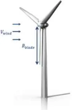
A single generator was designed before the SCTG design. Fig. 1 shows the layout of a typical three bladed offshore turbine with rotor radius R blade given by the blade length and V wind given by the wind speed.
The output power of the wind turbine is calculated by the kinetic energy (
) per unit time and power coefficient (
).
Fig. 1 Three blades wind turbine with a R blade and the V wind .
generator. The designed 15 MW superconducting generator will be effectively utilized in the construction of the large-scale wind power generation system.
Key Words : Generators, High-Temperature Superconductor, Wind Power Generation
(1)
where is the length of the blade, ρ is the density of the air, and V wind is the average wind speed [4]. Using the equation (1), we can calculate the rotor blade radius by knowing the rated wind speed and output power. Since the rated wind speed is designed to 12 m/s, rotor blade radius is calculated as 99 m where ρ =1.225 kg/m
3is the mass density of the air and C p =0.48 is maximum power coefficient.
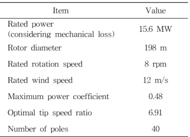
Table 1 shows the design specifications of the wind turbine.
Item Value
Rated power
(considering mechanical loss) 15.6 MW
Rotor diameter 198 m
Rated rotation speed 8 rpm
Rated wind speed 12 m/s
Maximum power coefficient 0.48 Optimal tip speed ratio 6.91
Number of poles 40
Table 1 Design Specifications of the Wind Turbine
2.2 Design Motivation and Concept of the SCTG
High electromagnetic force and torque of a large-scale superconducting wind power generator are important issued. Currently, large-scale superconducting synchronous generator(SCSG) is not verified about the high torque of HTS coil. According to equation (2), the torque is related to weight and diameter.
(2)
when the torque increases, the load increases and affects superconducting coils.
This paper proposed a design that the SCTG to solve this problem.
Fig. 2-3 show the block diagram of the 15 MW single generator and the SCTG. The rotor part consists of a superconducting field coil, a vacuum shield to cool the coil, and a rotor body to support the superconducting coil.
The stator part consists of a stator winding and a stator body to support the stator coil[5].
Fig. 2 Block Diagram of the 15 MW Single Generator
Fig. 3 Block Diagram of the 15 MW SCTG
2.3 Design of a Single Generator and the SCTG
The 15 MW class SCSG was designed considering the rated line-to-line voltage of 6.6 kV, rotating speed of 8 rpm and the number of poles of 40 poles. Turbine capacity of the single generator considering mechanical loss is 15.6 MW.
The 15 MW class SCTG was designed with
two generators and each generators are
considered the number of poles of 20 poles. The
SCTG configures the serial connection of two
7.8 MW generators on one shaft considering
mechanical loss. Fig. 4 shows the 3D structures
of the single generator and the SCTG.
Fig. 4 3D Structures of the Single Generator and SCTG
3. Simulation Results and Comparative Analysis
3.1 FEM Analysis Results of the 15 MW Class Single Generator
The single generator is designed in detail and simulated using 3D FEM program. The results included the magnetic field distribution and the peak voltage.
×
× (3)
The output voltage of the designed single generator is 6.55 kV using the output voltage equation (2). The output voltage of the designed SCTG is calculated as the same. Fig.
5 shows the perpendicular and maximum magnetic field distributions of the single generator. The perpendicular magnetic field and maximum magnetic field of the single generator are 2.87 T and 5.24 T, respectively.
3.2 FEM Analysis Results of the 15 MW Class SCTG
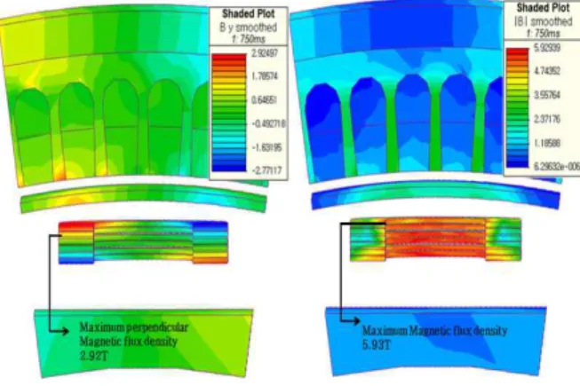
The SCTG is designed with two 7.8 MW generators. A 7.8 MW single generator is simulated using 3D FEM program to analyze the SCTG. Fig. 6 shows the perpendicular and maximum magnetic field distributions of the
7.8 MW single generator. The perpendicular magnetic field and maximum magnetic field of the single generator are 2.92 T and 5.93 T, respectively.
Fig. 6 Magnetic Field Distribution of the 7.8 MW Single Generator
3.3 Comparative Analysis of the 15 MW Class Single Generator and the SCTG
Table 2 shows specifications and FEM analysis results of the 15 MW class single generator and the SCTG.
Total weight of the single generator and the SCTG is 420.1 ton and 276.6 ton, respectively.
Total volume of the single generator and the Fig. 5 Magnetic Field Distribution of the 15 MW
Class Single Generator
SCTG is 135.6 m
3and 82 m
3, respectively.
The diameter and the torque of the SCTG are smaller than the single generator. Since the diameter is small, the size of the nacelle is also reduced. These results will be effectively utilized to the design of a large scale SCSG considering the cost.
Items Single
generator SCTG Turbine capacity
(considering mechanical
loss) 15.6 MW 15.6 MW
Generator capacity (considering mechanical
loss) 15.6 MW 7.8 MW
*2ea
Rated L-L voltage 6.6 kV 6.6 kV Rated armature current 1364.65 A 682.32 A Rated torque 18.62 MN·m 9.31 MN·m Rotating speed 8 rpm 8 rpm Turns of stator coil 15 turns 15 turns Turns of field coil 320 turns 350 turns
Number of slot 240 120
Number of poles 40 20
Number of layer 6 6
Operating current 340 A 345 A Air-gap length 30 mm 30 mm Maximum magnetic field 5.24T 5.93 T Perpendicular magnetic
field 2.87 T 2.92 T
Total length of
superconducting wires 148.7 km 163.82 km Outer diameter of
superconductor generator 8.59 m 4.66 m Total weight 420.1 ton 276.6 ton Total volume 135.6 m3 82 m3
Table 2 Specifications and FEM Analysis
Results of the 15 MW Class Single Generator and the SCTG
4. Conclusion
We discussed the design and analysis of the SCTG which can alternate large scale wind generator. The SCTG is designed to connect two generators in series on one shaft. The magnetic field distributions of the generators were analyzed using a 3D FEM program. The results show that the diameter and torque of the SCTG is smaller than a single generator and the SCTG is advantageous over a single generator in terms of weight and volume. This result shows that a SCTG is one of the good candidates for further large scale wind turbine generators considering economy. The disadvantage of using SCTG is that there are two generators, so shaft torsion can affect the power converter. Therefore, we will further study the influence of the shaft torsion.
Acknowledgements
This research was supported by Changwon National University in 2017~2018.
References