* Corresponding Author : [email protected]
+ 이 논문은 2017-2018년도 창원대학교 자율연구과제 연구비 지원으로 수행된 연구결과임.
Manuscript received January 8, 2019 / revised February 22, 2019 / accepted February 26, 2019
1) 창원대학교 전기공학과, 제1저자 2) 창원대학교 전기공학과, 제2저자 3) 창원대학교 전기공학과, 제3저자 4) 창원대학교 전기공학과, 제4저자 5) 창원대학교 전기공학과, 교신저자
계자 코일 구조에 따른 초전도 풍력 발전기의 모듈화 된 HTS계자 코일의 특성 분석
+
(Characteristic Analysis of Modularized HTS Field Coils for a Superconducting Wind Power Generator According
to Field Coil Structure)
투덴수런 오운자르갈1), 고 병 수2), 성 해 진3), 박 민 원4), 유 인 근5)*
(Oyunjargal Tuvdensuren, Byeong-Soo Go, Hae-Jin Sung, Min-Won Park, and In-Keun Yu)
요 약 풍력발전 시스템용 고온 초전도 (HTS) 발전기는 높은 효율과 기존 발전기에 비해 작은 크 기로 제작이 가능한 이점을 가지고 있다. 그러나 고온 초전도 발전기는 높은 전류 밀도와 자기장으로 인해 HTS 계자 코일에 작용하는 로렌츠 힘에 따른 문제가 발생할 수 있다. 본 논문에서는 계자 코일 구조에 따른 750 kW 급 초전도 풍력 발전기에 대한 모듈화 된 HTS 계자 코일의 특성 분석을 다룬 다. 모듈화 된 HTS 필드 코일의 구조는 3D 유한 요소법을 사용하여 얻은 전자기 및 기계 분석 결과 를 기반으로 설계하였고 모듈 코일의 전자기력도 분석하였다. 그 결과, HTS 코일의 수직 자기장과 최 대 자기장은 각각 2.5 T와 3.9 T로 나타났다. 지지대의 최대 응력은 유리 섬유 강화 플라스틱 재료의 허용 응력보다 작았으며, 변위는 허용 범위 이내로 발생하였다. HTS 모듈 코일 구조의 설계 사양 및 결과는 대용량 초전도 풍력 발전기 개발에 효과적으로 활용될 수 있다.
핵심주제어 : HTS 모듈 코일, 로렌츠 힘, 초전도 풍력 발전기, 초전도 코일 응력
Abstract High temperature superconducting (HTS) generators for wind power systems are attractively researched with the advantages of high efficiency and smaller size compared with conventional generator. However, the HTS generators have high Lorentz force problem, which acts on HTS field coils due to their high current density and magnetic field. This paper deals with characteristic analysis of the modularized HTS field coil for a 750 kW superconducting wind power generator according to field coil structure. The modularized HTS field coil structure was designed based on the electromagnetic and mechanical analysis results obtained using a 3D finite
1. Introduction
High temperature superconductors are being applied to electric power systems such as generators, motors and reactors [1-3]. Many researchers have tried to develop wind power generators with larger capacity, smaller size and lighter weight [4]. However, high temperature superconducting (HTS) wind power generators have some problems due to high electromagnetic force and high torque caused by their high current density, magnetic field, and low rotational speed [5-8]. The high magnetic field generates Lorentz force in the HTS coil, which would be a threat to the performance of the HTS wire [9]. Therefore, torque and Lorentz force of superconducting generators should be carefully investigated [10-11].
Previous researchers have studied the force analysis of the HTS generators [12-13]. The HTS generator consists of a stator and a rotor consisting of HTS components and has a large vacuum vessel for cooling. In addition, Lorentz force acts on the HTS field coil, so it is not easy to maintain the generator and to operate it safely. Moreover, the HTS field coils are connected in a series, thus if one HTS coil fails, the other coil breaks down.
These problems can be overcome by
modularization of the HTS field coil [8]. In order to maintain reliability, it is necessary to evaluate the mechanical stress and deformation in the generator design stage [14].
This paper deals with the characteristic analysis of a modularized HTS field coil for a 750 kW superconducting wind turbine according to field coil structure. The detailed structure of the module coil, such as current leads and supports, was designed to withstand high torques.
The 750 kW HTS generator, which consists of 84 pole racetrack type HTS module coils.
Each module coil consists of an HTS field coil, bobbin, coil support, cryostat and current lead (CL), and designed by 3D CAD program.
The HTS module coil was designed based on electromagnetic and mechanical analysis results obtained using a 3D finite element method (FEM), and the critical current density was evaluated by the perpendicular magnetic field. The structure of the module coil has mechanical stress and displacement due to the Lorentz force and torque, and these were analyzed using 3D FEM program.
As a result, the perpendicular and maximum magnetic fields of the HTS coils were 2.5 T and 3.9 T, respectively. Torque value was 0.304 MN·m. The maximum stress of the structure was less than the allowable stress of the glass-fiber reinforced plastic
element method. The electromagnetic force of the module coil was also analyzed. As a result, the perpendicular and maximum magnetic fields of the HTS coils were 2.5 T and 3.9 T, respectively. The maximum stress of the supports was less than the allowable stress of the glass-fiber reinforced plastic material, and displacement was within the acceptable range. The design specifications and the results of the HTS module coil structure can be effectively utilized to develop large-scale superconducting wind power generators.Key Words : HTS Module Coil, Lorentz Force, Superconducting Wind Power Generator, Superconducting Coil Stress
(GFRP), and displacement was within the acceptable range. The characteristic analysis results of the HTS module coil for 750 kW HTS generator can be effectively utilized to develop large-scale superconducting wind power generators.
2. Design of the 750 kW HTS Generator
The 750 kW HTS generator was designed based on the process as shown in Fig. 1 and the basic specifications of the generator were determined. Then, the electromagnetic design and analysis were implemented to confirm the output power and magnetic field of the generator. Next, the electromagnetic force, torque, gravity and centrifugal force of the HTS module coil were analyzed.
Fig. 1 Design process of the HTS module coil for superconducting generator
Based on the force analysis results, the HTS module coil structure was designed and analyzed using a 3D FEM program that includes von Mises stress and displacement due to forces generated in the HTS module coil. The 750 kW superconducting generator
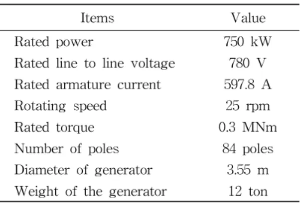
has 84 HTS modules. Table 1 shows the specifications of the 750 kW HTS generator.
The rotating speed and rated torque of the designed HTS generator are 25 rpm and 0.3 MN·m, respectively. The HTS generator can be divided into a rotor and stator parts. Rotor components are the HTS module coils, a cryostat, and a rotor body. The stator part comprised of stator teeth, stator coils, and a magnetic shield.
2.1 Structural design of the HTS module coil
The 84 HTS module coils were divided into 14 parts. Each part was mounted on a cryostat w ith a copper block and cooling pipes.
Items Value
Rated power 750 kW
Rated line to line voltage 780 V Rated armature current 597.8 A
Rotating speed 25 rpm
Rated torque 0.3 MNm
Number of poles 84 poles Diameter of generator 3.55 m Weight of the generator 12 ton Table 1 Specifications of the 750 kW HTS
generator
The structure of the HTS module coil of the 750 kW HTS generator were drawn by the 3D CAD program as shown in Fig. 2. The HTS module coil consists of the HTS field coils, coil bobbins, supports, a copper block, the CLs, a cryostat, and a cooling pipe. The shape of the field coil was racetrack-type, and three double pancake coils were stacked.
The cryostat was composed of stainless steel,
which was to prevent iron loss. The coil
supports are made of the GFRP to improve
the heat insulation between the cryostat and
the HTS coils. The HTS coils are covered
with bobbin and bobbin supports to protect the HTS coils from a high mechanical force.
The liquid neon gas flows inside the cooling pipes to cool the HTS module coils.
Fig. 2 Structural design of the HTS module coil
2.2 Characteristics of the 2G HTS wire
The 2G HTS wires have many different properties and performance, which have great influence on the design of the HTS generator.
In this paper, the properties of the 2G HTS wire given in [15] were used for designing a 750 kW HTS generator. Detailed specifications of the wire are summarized in Table 2. Fig. 3 shows the
curves of the HTS wire depending on operating temperature.
Items Value
Type GdBCO
Maximum rated stress 500 MPa
Thickness 0.15 mm
Width 12 mm
Insulation thickness 0.1 mm
Table 2 Characteristics of the superconducting 2G HTS wire
Fig. 3
curves of HTS wire3. Characteristic Analysis of the HTS Module Coil
3.1 Electromagnetic analysis and the results
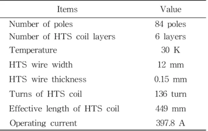
The 750 kW HTS generator was analysed using the 3D FEM program. The detail specifications of the HTS module coil for the 750 kW HTS generator were summarized in Table 3.
Items Value
Number of poles 84 poles
Number of HTS coil layers 6 layers
Temperature 30 K
HTS wire width 12 mm
HTS wire thickness 0.15 mm Turns of HTS coil 136 turn Effective length of HTS coil 449 mm
Operating current 397.8 A
Table 3 Detail specifications of the HTS module coil for the 750 kW HTS generator
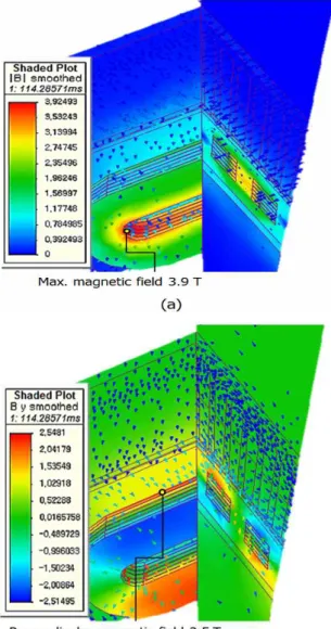
Fig. 4 shows the magnetic field distributions
of a 1/84 model of the 750 kW HTS
generator. The perpendicular and maximum
magnetic field were 2.5 T and 3.9 T,
respectively. The operating current was 397.8 A with 40% margin, and the current was determined by the properties of the HTS wire [15].
As a simulation result, the output voltage and rated torque were 551 V and 0.3 MN·m, respectively. Fig. 5 shows the output voltage and torque value of the 750 kW HTS generator under the full-load condition.
Fig. 4 (a) Magnetic field distribution and (b) perpendicular magnetic field of the 750 kW HTS generator
Fig. 5 (a) Output voltage and (b) rated torque of the 750 kW HTS generator
3.2 Mechanical analysis and the results
Torque is generated due to the magnetic field reaction between the rotor and stator parts. When the generator is in a no-load state, the generated magnetic field does not change because the armature current is zero, but the magnetic field generated under the full load condition is influenced by the armature current, thereby changing the electromagnetic force [16]. Therefore the mechanical stress due to the electromagnetic force of 750 kW HTS generator was analyzed under full load conditions.
(1)
where, is rated power, is the torque, is the angular velocity. Tangential force acting on a body moving in tangential direction of the body path is given as follows.
tan
(2)
where, is the radius of the rotor. The total torque and the tangential force of the generator, centrifugal and gravity forces were calculated by the equations (1), (2) (3) and (4). The torque and tangential, radial, gravity, centrifugal forces of the HTS module coil were examined.
·
· (3)
· (4)
where, is the mass of the HTS module coil and is the constant vector of the gravity (9.81
). As a calculation result, the output torque and the tangential force of one HTS module coil were 3.6 k
N·mand 2.2 kN, respectively. The gravity and the centrifugal forces of the HTS module coils were 1.5 kN and 1.2 kN, respectively. To analyze the mechanical stress of the HTS module coil, the axial direction and amplitude of the Lorentz force (5) at the HTS field coil are required.
× (5)
where, is the current density and is the magnetic flux density.
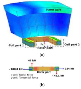
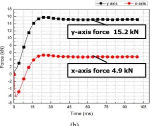
Lorentz force occurred perpendicular to the magnetic field and current direction of the HTS field coils [11]. Therefore, the HTS field coil is divided into two parts: coil part 1 and coil part 2, as shown in Fig. 6 (a). The
detailed tangential and radial forces of the HTS field coil are shown in Fig. 6 (b). The total radial force (x-axis) of the HTS field coil was 4.9 kN which was the sum of the 47 kN and -42.1 kN. In the case of tangential forces, the tangential force (y-axis) was 15.2 kN which was the sum of the 224 kN and -208.8 kN generated on both sides of the HTS field coil as shown in Fig. 7.
(a)
(b)
Fig. 6 (a) Directions and (b) amplitude of the tangential and radial forces of the HTS field coil for the 750 kW HTS generator
(a)
(b)
Fig. 7 (a) Tangential and radial forces of the HTS module coil, (b) Maximum tangential and radial forces of the HTS module coil
(a)
(b)
Fig. 8 (a) Maximum stress and (b) displacement of the HTS module coil
Based on the force analysis results, the HTS module coil structure was analysed using a 3D FEM program, including the von Mises stress and displacement by the generated force at the HTS module coil. The simulation results show that the von Mises stress and displacement of the HTS module coil were 39.3 MPa and 0.03 mm, respectively.
The stress and strain level inside the module should be limited below the allowable specifications of the HTS module to avoid the failure caused by stress and strain during the full potential of the coils. Fig. 8 (a) and (b) show the von Mises stress and displacement of the HTS module coils with support structures. The module coil support was made of GFRP. The tensile strength of the GFRP material was 280 MPa, allowable yield stress was 93.3 MPa. The stress value of the simulation result was 39.3 MPa which is lower than the allowable yield strength.
4. Conclusions
This paper discussed the characteristics analysis of the modularized HTS field coil for a 750 kW superconducting wind power generator. The modularized HTS field coil was designed based on the electromagnetic and mechanical analysis results obtained using a 3D finite element method. The electromagnetic force of the module coil also was analyzed. As a result, the perpendicular and maximum magnetic fields of the HTS coils were 2.5 T and 3.9 T, respectively. The operating current was 397.8 A with 40%
margin. The output voltage and rated torque were 551 V and 0.304 MN·m, respectively.
The maximum stress of the structure was
less than the allowable stress of the glass-fiber
reinforced plastic, and displacement was within the acceptable range. The characteristic analysis results of the HTS module coil for 750 kW HTS generator can be effectively utilized to develop superconducting wind power generators.
Acknowledgements
This research was supported by Changwon National University in 2017~2018.
References