pISSN 1229-3008 eISSN 2287-6251
Progress in Superconductivity and Cryogenics
Vol.16, No.2, (2014), pp.47~53 http://dx.doi.org/10.9714/psac.2014.16.2.047
```
1. INTRODUCTION
There are some differences of electromagnetic design between conventional and superconducting generator because superconducting generator using the 2G HTS wire hasn’t shorter air gap and iron core structure of rotor and stator which prevent flux leakage to air-gap outside.
In case of conventional generator, because structure of machine consists of iron core which is used to concentrate the magnetic flux in large part except for winding space of coils, a results of magnetic field distribution has a nearly no difference between 2D and 3D electromagnetic design.
However, in case of superconducting generator, the adversely effects of leakage flux which decrease the performance of generator can’t be ignored because superconducting generator without iron core structure has a much leakage flux than conventional generator. Therefore, to enhance the performance and reliability of generator system, 3D electromagnetic design including 3D magnetic field distribution should be necessarily performed.
In order to analyze more detailed characteristics of HTS generator, 3D FEA software is utilized to reduce the design errors which are caused by leakage flux due to the air-gap of over 50 mm and structure of air-core type. Moreover, we also consider the end part effect of HTS field coils which has a maximum magnetic flux density related to mechanical stability. In this paper, first of all, 2D conceptual electromagnetic design model of the HTS synchronous
generator has been redesigned including the rotor and stator design after that 3D magnetic field distribution and operating current (I
op) analysis of HTS field coil which affect generator performance have been performed. Last but not least, steady state operation characteristics of generator during the rated operation have been analyzed by commercial 3D FEA software.
2. ELECTROMAGNETIC DESIGN AND ANALYSIS OF A 10-MW-CLASS HTS SYNCHRONOUS
GENERATOR 2.1. Electromagnetic Design
TABLEI
BASIC DESIGN MODELS OF THE 10-MW-CLASS HTS GENERATOR.
Parameter Model
I Model
II Model
III Model IV
Rated output power (MW) 10 10 10 10
Frequency (Hz) 2 2 2 2
Rated output voltage (kV) 6 6 6 6
Field coil current (A) 207 207 207 207 HTS wire length (km) 1036 1158 1060 1635 Efficiency (%) 96.71 96.78 96.61 97.69
Rotor pole 24 24 24 24
Synchronous reactance (p.u) 0.1 0.1 0.2 0.2 Stator current
density(A/mm2) 3 3 3 2
Weight (ton) 136 137 139 206
Volume (m3) 50.72 49.09 51.9 69.9
3D electromagnetic design and electrical characteristics analysis of a 10-MW-class high-temperature superconducting synchronous
generator for wind power
J. H. Kim, S. I. Park, T. D. Le, and H. M. Kim *
Jeju National University, Jeju
(Received 29 April 2014; revised or reviewed 25 June 2014; accepted 26 June 2013)
Abstract
In this paper, the general electromagnetic design process of a 10-MW-class high-temperature superconducting (HTS) synchronous generator that is intended to be utilized for large scale offshore wind generator is discussed. This paper presents three-dimensional (3D) electromagnetic design proposal and electrical characteristic analysis results of a 10-MW-class HTS synchronous generator for wind power. For more detailed design by reducing the errors of a two-dimensional (2D) design owing to leakage flux in air-gap, we redesign and analyze the 2D conceptual electromagnetic design model of the HTS synchronous generator using 3D finite element analysis (FEA) software. Then electrical characteristics which include the no-load and full-load voltage of generator, harmonic contents of these two load conditions, voltage regulation and losses of generator are analyzed by commercial 3D FEA software.
Keywords: electrical characteristics, 2G HTS wire, HTS synchronous generator, magnetic field distribution
* Corresponding author: [email protected]
TABLEII
DESIGN PARAMETER OF THE 10-MW-CLASS HTS GENERATOR. Design Parameter Specifications
Rated output power [MW] 10.02
Rated frequency [Hz] 2
Rated rotating speed [rpm] 10
Rated output voltage [V] 6008
Rated torque [MN·m] 9.55
Efficiency [%] 96.326
Synchronous reactance [p.u] 0.1
Power factor 1
Machine weight [ton] 127.49
Machine volume [m3] 40.74
HTS Field Coil Armature Winding & Stator
Wire 2G HTS Conductor Flat type
copper Field coil type Race-
track Winding type Double layer
& full pitch Winding type Double
pancake Stator slot number 144
Length [mm] 1975 Length [mm] 2391
Field coil current
[A] 232 Stator coil current
[A] 962
Total winding
number 229170 Stator coil number
per phase 384
HTS wire
length [km] 1077 Copper wire
length [km] 6.482 Current density
[A/mm2] 206.7 Current density
[A/mm2] 3
Operating
temperature [K] 35 Insulating class F Current lead loss
[W] 17 Copper loss
[kW] 356
Max. magnetic
flux density [T] 11.38 Max. magnetic
flux density [T] 2.5
Fig. 1. Schematic diagram of the 10-MW-class HTS synchronous generator for wind power.
Table I presents some basic design proposals of a 10- MW-class HTS synchronous generator for wind power, which are designed by 2D numerical analysis method.
Model I is selected in 2D conceptual electromagnetic -design taking into account 2G HTS wire length and efficiency, volume and weight of generator among the above design proposals in order to analyze the electrical characteristics of HTS wind generator [1].
Table II lists the design parameter specifications of the 10-MW-class HTS synchronous generator designed by 2D analytical design code and 3D FEA software, and the
TABLEIII
MATERIALS AND WEIGHT OF CONFIGURING PART OF THE HTS GENERATOR. Materials Density
[kg/m3] Weight
[ton] Proportion [%]
HTS field coil
HTS wire 2G HTS 5700 6.96 5.46
Insulating
plate AL7075 2823 1.69 1.33
Bobbin
block AL7075 2823 2.44 1.91
Flux damper AL7075 2823 2.82 2.21
FRP core G10 1800 5.58 4.38
Armature coil Copper 8860 17.80 13.96 Mechanical shield Silicon
steel 7600 42.47 33.31
Rotating shaft SCM 440 8030 40.89 32.07
Housing SCM 440 8030 6.836 5.36
Total weight - 127.49 100
Fig. 2. Schematic view of a race-track type DP field coil for 10-MW-class HTS synchronous generator for wind power.
resulting conceptual design is displayed in Fig. 1. Direct drive train is adopted as drive train system of the 10-MW- class HTS generator in this design which has a low rotating speed of 10 rpm.
Generally, because of merit of compatibility between the generator and commercial power converter, generator design which has a high rated frequency by increasing the number of the generator poles is more economical.
However, the weight and volume of generator are increased and efficiency of generator is reduced. Therefore, in order to achieve a compact volume, lighter weight and meet the minimum frequency of 2 Hz which is applicable to commercial power converter, the number of field pole is limited to a 24-pole when design HTS synchronous generator.
Table III shows materials used for electromagnetic design and weight of configuring part of the HTS generator.
From calculation results of approximate weight of generator through the mass density property of materials used in each configuring part, total weight of generator is estimated at approximately 127.49 ton. A mechanical shield which accounts for the large volumes among configuring part of generator and a rotating shaft with a high mass density material for the mechanical strength of rotor take up about 65% of the generator weight. Also, the total volume of generator is calculated to 40.74 m
3.
Unit: mm
J. H. Kim, S. I. Park, T. D. Le, and H. M. Kim
TABLEIV
SPECIFICATIONS OF THE 2G HTS WIRE.
Conductor Property Value
Conductor type (Gd,Y)BCO
Thickness [mm] 0.16
Width [mm] 6
Critical current [A] @77 K, SF ≥120
Critical tensile strength [MPa] @77 K 550 (longitudinal direction)
Fig. 3. Cross sectional view of air-core-type stator coils.
One HTS field pole for the 10-MW-class synchronous generator consists of eight layers of double-pancake (DP) coils with an insulating plate in between two pancake coils and is shown in Fig. 2.
The race-track-type HTS field coils are wound by the way of insulating winding method with electrical insulating layer of 0.027 mm. The width and thickness of the 2G HTS wire have 6 and 0.16 mm, respectively. Furthermore, the specifications of the 2G HTS wire manufactured by SuperPower Corporation used to design the HTS field coils are listed in Table IV. Minimum critical current value of the 2G HTS wire has over 120 A at the cooling temperature of 77 K in the self-field condition. 2G HTS wire includes the copper stabilizer of 0.1 mm thickness.
The length per pole of the 2G HTS wire, which is important for designing the superconducting rotating machine, is approximately 45 km. Furthermore, the total length of the 2G HTS wire is approximately 1077 km. Also, the number of winding per pole is 9602.
The stator is designed by an air-core stator manufactured by Fiber Reinforced Plastics (FRP) which is capable of high voltage of generator terminal by increasing the dielectric strength of stator. Stator winding type is double layer & full pitch and the total number of stator slots is 144.
There are series winding of eight turns in each layer and cooling channel between stator slots of two layers as shown in Fig. 3. Three-phase armature coils of stator wound by flat type copper.
A relatively lower current density of stator increases manufacturing costs of generator because of increasing the amount of copper used for stator winding. On the other hand, it is possible to manufacture HTS generator that has a high efficiency by reducing the stator cooling loss.
Therefore, stator current density is set at 3 A/mm
2.
In order to use Modular Multilevel Converter (MMC) system that has a high voltage level of 6 ~33 kV and can achieve the compact and economical wind turbine system by eliminating the grid-side step-up transformer, the rated output voltage of generator is designed to 6008 V [2].
2.2. Electromagnetic Analysis
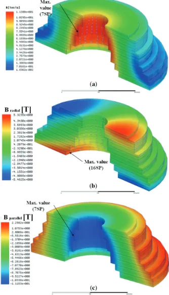
Fig. 4. The magnetic flux density distribution on the central section of the straight part of HTS field coil: (a) perpendicular direction and (b) parallel direction.
Fig. 5. The magnetic flux density distribution at the curve part of HTS field coil: (a) composite value, (b) radial (perpendicular) and (c) parallel direction.
49
Fig. 6. Distribution of electromagnetic force at the curve part of the race-track-type HTS field coil.
Fig. 7. The characteristic curve of the 2G HTS wire in perpendicular direction.
Fig. 4 shows the 3D magnetic field distribution of (a) perpendicular and (b) parallel direction on the central section of the straight part of HTS field coil calculated from the 3D FEA software. The maximum magnetic flux density of the perpendicular and parallel direction reaches about 5.83 T in a single-pancake (SP) coil in the 1
stand 16
thlayer, 9.38 T in SP coil in the 7
thlayer, respectively.
We also investigated the magnetic field distribution of the parallel direction at the curve part of HTS field coil as shown in Fig. 5. As results of the maximum magnetic flux density analysis, the composite value, radial and parallel directions are 11.38, 5.46 and 11.15 T, respectively.
Consequently, the results of the 3D magnetic field distribution analysis show that the maximum value of the perpendicular and parallel magnetic field that determines a critical current and the Lorentz force are approximately 5.83 T and 11.15 T, respectively.
Fig. 6 shows the distribution of electromagnetic force which is related to mechanical stress. From the direction of the HTS wire width (ab-plane), the Lorentz force generated in the HTS field coil caused by the magnetic field in the
TABLEV
MAXIMUM MAGNETIC FLUX DENSITY OF THE PERPENDICULAR DIRECTIONS IN EACH LAYER OF THE FIELD COIL.
Layer
of pancake coil Straight parts Curvature parts Value [T] turns Value [T] turns
1SP 5.83 407 5.3 285
2SP 5.55 588 4.66 488
3SP 4.68 517 4.0 334
4SP 4.02 517 3.49 372
5SP 3.67 511 2.99 320
6SP 3.74 539 3.22 55
7SP 2.88 579 2.52 554
8SP 2.35 590 2.57 591
9SP 1.91 536 2.48 536
10SP 2.08 591 2.77 578
11SP 2.27 72 3.23 579
12SP 3.19 53 4.08 684
13SP 3.4 59 4.06 600
14SP 4.21 60 4.79 40
15SP 4.83 181 4.71 456
16SP 5.83 228 5.46 191
Fig. 8. Critical current curve based on maximum magnetic field and operating temperature of 40 K at the straight section of HTS field coil.
Fig. 9. Critical current curve based on maximum magnetic field and operating temperature of 30 K at the straight section of HTS field coil.
-parallel direction (B//ab) creates a radial stress and hoop
stress along the curve parts HTS field coil. Additionally,
the compressive force acts as a shear stress because of the
perpendicular (B//c) magnetic field [3]. Lorentz force (F
r)
acts as a radial direction at the curve part of HTS field coils
because of maximum value of parallel magnetic flux
density (11.15 T) as shown in Fig. 6.
J. H. Kim, S. I. Park, T. D. Le, and H. M. Kim
Fig. 7 shows the in-field property of 2G HTS wire use to calculate the operating current of HTS field coils for 10-MW-class HTS generator [4]. HTS wire has the critical current (I
c) properties which depend on various operating temperatures of HTS wire and various directions of magnetic flux density affecting HTS wire surface. Because the critical current of HTS wire is decreased by magnitude of magnetic field in perpendicular direction as shown in Fig.7, it is necessary to calculate the critical current of HTS wire for designing the reliable HTS field coils.
Because the operating temperature of the 10-MW-class HTS generator is targeted from around 40 to 30 K, in-field property of 40 and 30 K in Fig. 7 and also magnetic field of perpendicular direction in Table V used to calculate the critical current of HTS wire. As results of magnetic field distribution analysis, since maximum magnetic flux density of the perpendicular direction is generated at the straight parts of HTS field coil, critical current is calculated on basis of that of straight.
Fig. 8 and Fig. 9 represent critical current characteristics curve based on in-field property of 40 and 30 K, respectively. In case of operating temperature in 40 K, critical current of each SP coil varies from 266 to 563 A.
Because maximum magnetic flux density of the perpendicular direction is generated at 1SP coil, the lowest critical current is calculated in SP coil in the 1
stlayer.
Operating current of HTS field coils is set to 232 A which reaches about 87% of critical current. This value isn’t a sufficient level to operate HTS field coil in the transient state which has a potential to create a quench.
Therefore, operating temperature of HTS generator is needed to be decreased in order to have a stability margin of operating current. Also, in case of using the equal HTS wire, operating current can be selected based on 266 A which is critical current of SP coils in the 1
stand 16
thlayer.
Meanwhile, in order to increase efficiency of using wire and reduce the manufacturing cost of HTS field coils, it is necessary to choose optimized wire according to the critical current in each SP coils. Especially, in case of SP coil in the 9
thlayer, efficiency of using wire is lower because operating margin (I
op/I
c) is approximately 2.4 which means that critical current of SP coil in the 9
thlayer has 2.4 times greater than operating current of HTS field coil.
In case of operating temperature in 30 K, 432 A of critical current in SP coil in the 16
thlayer has 1.8 times greater than 232 A of operating current of HTS field coil.
Although this value is considered to have high operating reliability so that efficiency of using wire is lower. It is concluded that to set operating temperature in 35 K levels is reasonable design.
3. ELECTRICAL CHARACTERISTICS ANALYSIS OF A 10-MW-CLASS HTS SYNCHRONOUS
GENERATOR
Fig. 10 shows magnetic flux density distribution of the 10-MW-class HTS synchronous generator during the rated operation (field current of 232A, rotation speed of 10 rpm and rated load resistance). Maximum magnetic flux density in HTS field coil is 11.38 T and the maximum magnetic
Fig. 10. The magnetic flux density distribution of the 10-MW-class HTS generator at the full-load operation.
Fig. 11. Comparison of no-load and full-load phase voltage waveform.
Fig. 12. THD analysis results of no and full-load voltage.
-flux density in radial direction (Br) at the central points of double-layer armature windings in circumferential direction which directly affects to output performance of HTS generator is approximately 1.8 T.
51
Fig. 11 shows no-load and full-load terminal voltage waveform at the three-phase armature winding. The root mean square (RMS) values of no-load and full-load phase voltage are 3595 V and 3469 V, respectively.
Because the harmonic components included in electrical output power causes increasing noise, vibration and electrical losses of the generator and cost of the Power Conversion System (PCS), harmonics contents of electrical output power such as output voltage and load current must be considered in the design step [5]. Total Harmonic Distortion (THD) is defined as the ratio of sum of RMS values of the harmonic components to RMS value of fundamental component and used to calculate the harmonics contents.
Fig. 12 shows results of Voltage Total Harmonic Distortion (VTHD) of no and full-load phase voltage. As results of VTHD for no-load voltage, A, B and C phase are 2.3, 2.9 and 1.9%, respectively, and are obtained lower levels of harmonics components which make sinusoidal waveform of HTS generator electrical output as shown in Fig. 11. Those values do not pass PCS so VTHD can be improved.
In case of air-core type HTS generator, these results are attributed to the characteristics of the non- harmonic components due to without iron core which saturates the magnetic flux in stator slots. Therefore, superconducting generator can reduce the noise, vibration and electrical losses and increase economic efficiency of wind turbine including the PCS through elimination of harmonics.
Table VI summarizes some results of the electrical characteristics analysis, which is computed by full-load analysis. Output power capacity per each phase and total output power of HTS generator is approximately 3.3 and 10.02 MW, respectively. Also, average value of the voltage drop in three-phase is calculated as 126 V.
The voltage regulation of the generator means the degree of changes in the terminal voltage due to the application of loads on the generator and is expressed by (1)
% 100
×
=
n n O
V V
ε V - (1)
where ε, V
Oand V
nare the voltage regulation, no-load, and full-load terminal voltage, respectively.
TABLEVI
ELECTRICAL CHARACTERISTICS RESULTS. No-load
voltage Full-load voltage Voltage
drop Rated current Output
power Voltage regulation
[V] [V] [V] [A] [MW] [%]
A phase 3611 3465 146 965.5 3.346
3.65 B phase 3596 3466 130 962.6 3.336 C phase 3578 3476 102 962.8 3.346
3-phase output - - - - 10.02
TABLEVII
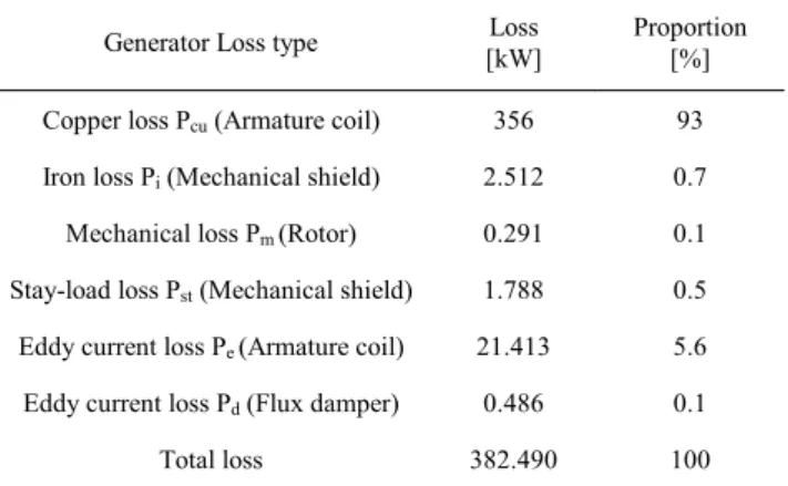
GENERATOR LOSSES OF THE 10-MW-CLASS HTS GENERATOR. Generator Loss type Loss
[kW] Proportion [%]
Copper loss Pcu (Armature coil) 356 93 Iron loss Pi (Mechanical shield) 2.512 0.7 Mechanical loss Pm (Rotor) 0.291 0.1 Stay-load loss Pst (Mechanical shield) 1.788 0.5 Eddy current loss Pe (Armature coil) 21.413 5.6 Eddy current loss Pd (Flux damper) 0.486 0.1
Total loss 382.490 100
One of the ideal characteristics of generator is voltage stability which is to provide a constant voltage from generator to power systems regardless of load changes. In other words, the voltage stability increases as the voltage regulation becomes smaller [6]. It is difficult to reduce the voltage regulation less than 15% even with additional excitation control of the field coil so that voltage drop of conventional synchronous generator is large according to the load conditions because of large synchronous reactance (about 1.0 p.u). However, since synchronous reactance of HTS generator in this design is 0.1 p.u, voltage regulation is a relatively low levels as 3.65% with resistance load.
This value is a below level of that of 5% without excitation controls and does not pass PCS [7]. Therefore, it is concluded that the margin for improvement of voltage regulation remains.
Table VII lists generator loss analysis results. The total loss of generator is calculated to approximately 382.5 kW and the armature copper loss reaches almost 93% of the total loss of generator and is about 356 kW.
Since three-phase output power of the 10-MW-class HTS generator, which is computed by above electrical characteristics analysis in Table VI is approximately 10.02-MW, generator efficiency is calculated as about 96.326% from a commercial efficiency of generator.
4. CONCLUSIONS
This paper has discussed the general electromagnetic design process of a 10-MW-class HTS synchronous generator. Electromagnetic deign model regarded to suitable designs of 10 MW class HTS generator is selected and analyzed to consider the practical considerations such as HTS wire length, efficiency, volume and weight of machine.
With the dramatically development on 2G HTS wire
production by 2020 to achieve economical price level of
manufacturing cost for large scale wind generator
compared to conventional generator , it is estimated that the
production capacity will be increased 36 times, whereas the
manufacturing cost wire will be decreased 10 times [8]. As
consequently, total estimation of 1077 km 2G HTS wire
length in order to manufacture the field coil of 24 poles for
J. H. Kim, S. I. Park, T. D. Le, and H. M. Kim
10-MW-class HTS generator is certainly economically suitable for fabricating with the acceptable price level.
Generator efficiency considering the electrical losses and mechanical loss was approximately 96.3 % and volume and weight of generator related to wind turbine construction in economic and technical aspects were estimated to 127.45 ton, 40.74 m
3, respectively.
As results of electrical characteristics analysis of HTS generator, THD and voltage regulation of generator were 2.36 and 3.65%, respectively.
We will be conducting the additional study considering detailed design of HTS field coils including structural and thermal design. In addition, cryogenic system which is currently being developed and studied will be applied to design superconducting generator system.
ACKNOWLEDGMENT
This research was supported by the 2014 scientific promotion program funded by Jeju National University.
REFERENCES
[1] Ji hyung Kim, “3D electromagnetic design and power analysis of a 10 – MW – class high-temperature superconducting synchronous -generator for wind power,” Master of science thesis, Faculty of applied energy system graduate school, jeju national university, Feb.
2014.
[2] Xibo Yuan, Yongdong Li, Jianyun Chai, “A transformerless modular permanent magnet wind generator system with minimum generator coils,” Applied Power Electronics Conference and Exposition (APEC), 2010 Twenty-Fifth Annual IEEE, pp.
2104-2110, Feb.2010.
[3] Ji Hyung Kim, Sa Il Park, Thanh Dung Le, Hyun Chul Jo, Young-Sik Jo, Yoon Hyuck Choi, Haigun Lee, Ho Min Kim,
“Analysis of the mechanical characteristics of a 17-MW-class high temperature superconducting synchronous motor,”
InternationalConference on Superconductivity and Magnetism, p.
533, Antalya, 2014.
[4] V Selvamanickam, Y Yao, Y Chen, T Shi, Y Liu, N D Khatri, J Liu, C Lei, E Galstyan and G Majkic, “The low-temperature, high-magnetic-field critical current characteristics of Zr-added (Gd,Y)/Ba2Cu3Ox superconducting tapes,” Supercond. Sci.
Technol., vol. 25, no. 12, p. 125013, Dec. 2012.
[5] Rouhollah Shafaie and Mohsen Kalantar, “Design of a 10-MW-class wind turbine HTS synchronous generator with optimized field winding,” IEEE Trans. Appl. Supercond., vol. 23, no. 4, p. 5202307, Aug. 2014.
[6] Hyung-Wook Kim, Young-Sik Jo, Jin-Hong Joo, Sail Park, Ho Min Kim and Jin Hur, “ Study of hybrid-type superconducting field coil for superconducting rotating machines,” IEEE Trans. Appl.
Supercond., vol. 24, no. 3, p. 5201204, Jun. 2014.
[7] M.Frank, J.Frauenhofer, P.van Hasselt, W.Nick, H.-W.Neumueller, and G. Nerowski, “Long-term operational experience with first siemens 400 KW HTS machine in diverse configurations,” IEEE Trans. Appl. Supercond.,vol.13, no.2, pp. 2120-2123, Jun. 2003.
[8] S. I. Park, J. H. Kim, T. D. Le, and H. M. Kim, “Comparison of superconducting generator with 2G HTS and MgB2 wires,”
Progress in Superconductivity and Cryogenics, vol. 15, no. 4, pp.
48-52, Dec. 2013.
![Fig. 7 shows the in-field property of 2G HTS wire use to calculate the operating current of HTS field coils for 10-MW-class HTS generator [4]](https://thumb-ap.123doks.com/thumbv2/123dokinfo/5380532.410361/5.892.477.785.122.476/shows-field-property-calculate-operating-current-field-generator.webp)