1106
-Abstract – A flux pump (FP) can inject the DC current into hightemperature superconducting (HTS) field coils of a HTS rotating machine without slip ring and current lead. However, it has limits to improve the value of DC current, and has time constants of DC current according to inductances of the HTS field coils. When a large-scale HTS generator with the FP is designed, a proper point about the inductance, field current, and time constant is demanded to decide parameters of the generator.
In this paper, a parameter tuning skill of a large-scale superconducting wind power generator for applying a FP has been proposed. The design of the FP has been fixed, and 12 MW HTS generators have been variously designed by adjusting parameters related with the inductance of the HTS field coil. The induced current values have been calculated based on the FP design. The time constants of the induced currents depending on the DC current values and inductances of the generator have been represented. The results of the parameter tuning of the HTS generator have been discussed in detail.
1. Introduction
An high temperature superconducting (HTS) synchronous machine requires a power source and transmission devices such as slip rings and current leads, which are capable of carrying large DC current. However, these components require a complex structure and increase the heat invasion from ambient temperature to cryogenic temperature. To solve these problems, an flux pump (FP) capable of inducing DC current into the HTS field coils of the machine is suggested [1-3].
In the case of high temperature superconducting (HTS) field coils in a large scale HTS generator with low rotational speed, the induced DC current by the FP has a long time constant owing to high inductance of the field coil. Whereas, the lower inductance of the HTS field coil requires the higher field DC current to generate the same output power of the generator. The value of the induced current by the FP has a limit. Therefore, a proper point about the inductance, field current, and time constant to design the large-scale HTS generator for applying the FP is demanded.
In this paper, a parameter tuning skill of a large-scale superconducting wind power generator for applying a FP has been proposed.
The design of the FP has been fixed, and 12 MW HTS generators have been variously designed by adjusting parameters related with the inductance of the HTS field coil such as the number of HTS poles, the number of HTS field coil layers, an effective length of HTS field coil, and field current using a finite element method (FEM) program. The rotating speeds of the FP are determined according to the design specifications of the 12 MW HTS generators. Total resistances of the FP depending on the required DC field current values have been calculated by the formula [3]. By the resistance of the FP and inductance per pole of the generator, the time constant has been estimated.
As a result, for applying the FP to the large-scale HTS generator, the DC field current is 340 A and the time constant is 46 hr for the field coil. The analysed results will be effectively utilized to design large-scale superconducting wind power generators minutely.
2. Conceptual design of a 12 MW HTS generator with a flux pump
2.1 Configuration and driving principles of the HTS generator with the FP
Fig. 1, shown below, illustrates the configuration of the HTS generator with the FP. The large-scale HTS generator consists of HTS field coils, rotor body, vacuum vessel, copper stator coils, and stator body. These components are applied usually to iron-cored HTS rotating machine. The HTS generator in this paper considers a modularization design which means all of the HTS field coils are separated structurally and not connected in series. This design improves stability of the generator when some field coils are faulted.
The FPs are the permanent magnets rotating nearby the HTS stator wire. When the magnetic flux of the magnets penetrates the HTS wire, the DC current is induced causing quasi-DC electro motive force (EMF) in the HTS wire by Faraday’s law and flows into the HTS field coil. The components of the FP are divided to rotor and stator parts. The rotor parts are permanent magnets and an iron-disk. The stator parts are an HTS wire, an iron-disk, and iron-poles. The FP per the HTS field coil is composed for the modularization design. The stator parts are located in the vacuum vessel of the generator for connecting the HTS wire to the HTS field coil directly. The rotor parts interlock with stator teeth of the generator to turn the rotor parts.
<Fig. 1> Configuration of the HTS generator with the FP 2.2 Specifications of the HTS generator with the FP
The material and mass density of each component of the HTS generator with FP are shown in Table 1, and the specifications of the fundamental design are represented in Table 2.
The stator body of the generator uses a laminated silicon steel to reduce the total length of HTS wire. The FP has long air-gap between the rotor parts and the stator parts because the wall of the vacuum vessel is located in the air-gap. It means that the magnetic flux density to induce DC current in the FP is decreased owing to long air-gap. The cold rolled steel is used for the iron-disk of the FP to increase the magnetic flux density.
플럭스 펌프 적용을 위한 대용량 초전도 풍력발전기 파라미터 튜닝
성해진*, 고병수*, 박민원*, 유인근*
창원대학교*
Parameter tuning of a large-scale superconducting wind power generator
for applying a flux pump
Hae-Jin Sung*, Byeong-Soo Go*, Minwon Park*, and In-Keun Yu*
Changwon National University*
1107
-<Table 1> The material and mass density of each component of the HTS generator with FPHTS generator
Parts Material Density (kg/m3)
Rotor wire YBCO 11,000
Rotor body 304 Stainless steel 8,190 Vacuum vessel 304 Stainless steel 8,190 Stator wire Copper 8,940 Stator body M-27 24 Ga 7,650
FP
Magnets Neodymium magnet(N52) 7,539 Iron-disk Cold steel 6,800 HTS stator wire YBCO 11,000
<Table 2> Specifications of the fundamental design of the HTS generator with FP
HTS generator
Specifications Value Rated output power 12.3 MW Rated line-to-line voltage 6.6 kV Rated rotation speed 10 rpm Operating temperature 20 K The length of air gap 20 mm Current density of stator wire 5 A/mm2
Num. of field coil turns/layer/pole 500 Num. of stator coil turns 15 Num. of stator slots/pole 6
Width of HTS wire 12 mm Thickness of HTS wire 0.1 mm FP Outer diameter 200 mm Num. of magnets 30 Num. of poles 12
3. Results and discussions
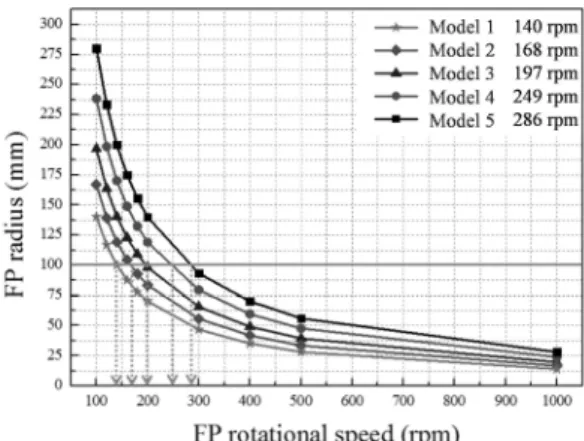
The parameters related with the inductance of the generator are changed as shown in Table 3 to confirm the resistance of the flux pump and the time constant. When comparing Model 1 and Model 5, the inductance per pole of Model 1 is much higher than Model 5 to generate the same output power. The DC field current of Model 1, on the other hand, is lower than Model 5 because the field current is decided by the magnetic field density of the field coil. Fig. 2 shows the FP rotational speeds depending on the radius of FP and Model, and the dynamic resistance of the FP is calculated using a formula [3]. A adjustable resistance of the FP is changed to control the value of induced DC current of the FP. Therefore, the DC current of the FP is induced as much as the field coil of the generator requires. Fig. 3 represents the total resistance, which is the sum of dynamic and adjustable resistances, and the time constant according to the inductance and DC field current of the generator. When considering the time constant and total resistance, Model 1 is proper for applying the FP.
Table 3> The control parameters of the generator Parts Model1 Model2 Model3 Model4 Model5 Num. of rotor poles/layers 16/10 20/8 24/8 30/6 36/4 Operating current (A) 281 294 298 313 340 Effective length of field coil (mm) 1,000 1,000 1,000 500 600 Inductance per pole (H) 51 25.58 17.48 7.74 4.27
<Fig. 2> FP rotational speeds depending on FP radius and inner stator radius of each Model
<Fig. 3> Time constants and total resistance of the FP 4. Conclusions
In this paper, a parameter tuning skill of a large-scale superconducting wind power generator for applying a FP was proposed. A 12 MW HTS generators were variously designed by adjusting parameters related with the inductance of the HTS field coil. The induced current values were calculated, and the time constants of the induced currents depending on the DC current values and inductances of the generator were estimated. When considering the time constant and the total resistance of the FP, the DC field current of 340 A and the time constant of 46 hr were suitable to the generator for applying the FP.
Acknowledgement
[References]
[1] Jacek F. Gieras, “Superconducting Electrical Machines State of the Art”, Przeglad Elektrotechniczny, 12, p.1-19, 2009
[2] T. Nakamura, K. Nagao, T. Nishimura and K. Matsumura, “An induction/synchronous motor with high temperature superconductor/normal conductor hybrid double-cage rotor windings”, Supercond. Sci. Technol, 22, 2009
[3] Zhenan Jiang, K. Hamilton, Naoyuki Amemiya, R. A. Badcock and C. W. Bumby, “Dynamic resistance of a high-Tc superconducting FP”, Applied Physics Letters, 105, p.112601, 2014
This work was supported by the Power Generation & Electricity Delivery Core Technology Program of the Korea Institute of Energy Technology Evaluation and Planning (KETEP), granted financial resource from the Ministry of Trade, Industry & Energy, Republic of Korea.