Manuscript received on August 30, 2019, Revised on September 30, 2019, Accepted on October 4, 2019
1 KEPCO Research Institute, Korea Electric Power Corporation, 105 Munji-ro Yuseong-gu, Daejeon 34056, Republic of Korea
2 Department of Electrical Engineering, Changwon National University, Changwon 641-773, Republic of Korea
Critical Characteristics Estimation of a Large-Scale HTS Wind Turbine Generator Using a Performance Evaluation System
Taewon Kim
1, Sang-Kyun Woo
1, Changhyun Kim
2†Abstract
Large-scale High Temperature Superconducting (HTS) wind power generators suffer from high electromagnetic force and high torque due to their high current density and low rotational speed. Therefore, the torque and Lorentz force of HTS wind power generators should be carefully investigated. In this paper, we proposed a Performance Evaluation System (PES) to physically test the structural stability of HTS coils with high torque before fabricating the generator. The PES is composed of the part of a pole-pair of the HTS generator for estimating the characteristic of the HTS coil. The 10 MW HTS generator and PES were analyzed using a 3D finite element method software. The performance of the HTS coil was evaluated by comparing the magnetic field distributions, the output power, and torque values of the 10 MW HTS generator and the PES. The magnetic flux densities, output power, and torque values of the HTS coils in the PES were the same as a pole-pair of the 10 MW HTS generator.
Therefore, the PES-based evaluation method proposed in this paper can be used to estimate the critical characteristics of the HTS generator under high magnetic field and high torque before manufacturing the HTS wind turbines. These results will be used effectively to research and manufacture large-scale HTS wind turbine generators.
Keywords: Large-Scale HTS Generator, Lorentz Force, Performance Evaluation, Torque, Wind Turbine
I. INTRODUCTION
The rated power of individual generators of a wind turbine has been gradually increasing [1]. In the existing large-scale wind power generation systems, gearless method is adopted to reduce the weight of Nacelle [2]. On the other hand, high-temperature superconducting (HTS) coils have high current density and magnetic field, so HTS generators are suitable for large-scale wind power generation systems and can significantly reduce the volume and weight compared to conventional generators. However, the large-scale HTS wind power generators suffer from high electromagnetic force and high torque due to their high current density, magnetic field, and low rotational speed [4]-[6]. Therefore, electromagnetic analysis and verification of HTS wind power generators are required before production.
This paper deals with the estimation of critical
characteristics of a large-scale HTS wind power generator using Performance Evaluation System (PES). The 10 MW HTS generator with 40 HTS coils and an armature was designed.
The PES consists of the three HTS coils used in the HTS generator and the corresponding armature winding. The magnetic field attenuation has occurred at both ends of the HTS coils as the three HTS coils are linearly arranged [7].
Therefore, three HTS coils are required to generate a pole- pair. In the design of the PES, the HTS coils are stationary and the armature is moved by a motor. The armature passes the three fixed HTS coils at a speed of about 3.8 m/s, which is equal to 10 rpm of the 10 MW HTS generator. The 10 MW HTS generator and PES were designed based on a rated line-to- line voltage of 6.6 kV and 330 V, respectively.
The 10 MW HTS generator and PES were analyzed using
a 3D Finite Element Method (FEM) program. The PES was
designed based on a 1/20 model of the full 40-pole 10 MW
HTS generator. Electromagnetic analysis results of the 10 MW HTS generator and PES were compared for magnetic field distributions, the output power, and torque values. The results of the comparison of the torque values of the 10 MW HTS generator with the PES were discussed to demonstrate the feasibility of the PES. The torque values of the 10 MW HTS generator and the PES were 10.02 MN·m and 488 kN·m, respectively. To compare the output power and torque of the PES with the generator, it can be treated the same as the one pole pair of the 10 MW HTS generator. Therefore, the PES for testing the 10 MW HTS generator can be used to test the mechanical strength of the HTS coil under high magnetic field and high torque. The critical characteristics estimation method of the 10 MW HTS generator will effectively be utilized to develop a large-scale wind power system.
II. COMPASITION OF A 10 MW HTS GENREATOR AND CONCEPT OF A PES
A. Specifications of HTS Coils for the 10 MW HTS Genrator The specifications and the dimensions of the HTS coil are
summarized in Table 1. The HTS coils consisted of racetrack- type double pancake coils. The HTS wire was coated with a flat conductive tape having a thickness of 0.15 mm and a width of 10 mm. Metallic insulation (MI) was applied to the HTS pancake coil. The MI coil was co-wound with an HTS wire and a stain-less steel tape with a thickness of 0.10 mm.
The advantages of MI coil are a low bypassing current that results in a lower charging time, and better thermal stability as well as an enhanced mechanical integrity [8][9].
In this paper, the difference between the 10 MW superconducting generator and other superconducting generators is that the module coils are adopted to a rotor part.
The HTS module coil means that each HTS coil has its own individual cryostat. The advantage of the module coils is that it can reduce the vacuum vessel, and make it easier to repair and maintain the HTS coils compared to the HTS generators which have to cool the entire rotor. The module coil consists of one cryostat, coil bobbins and supports, heat exchanger, cryo-cooler, and one HTS coil [10].
Table 1
Specifications and Dimensions of the HTS Coils for 10 MW HTS Generator
Specifications Value
Turns of field coil 260
Number of layer in HTS rotor coil 6
Operating current 253 A
Operating temperature 30 K
Width of bobbin 250 mm
Width of coil 65 mm
Effective length of coil 700 mm
Height of coil 74 mm
Total length of a 1 pole HTS wire 3.6 km Table 2
Specifications of the Designed 10 MW HTS Generator
Specifications Value
Rated output power 10 MW
Rated L-L voltage 6.6 kV
Rated armature current 918.5 A
Rotating speed 10 rpm
Rated torque 10.02 MN·m
Number of poles 40
Number of layer 6
Rated frequency 3.33 Hz
Operating temperature 30 K
Air-gap length 30 mm
Cross sectional area of YBCO wire 1.5 mm2 Table 3
Specifications of the Designed PES
Specifications Value
Rated output power 525 kW
Rated L-L voltage 330 V
Rated armature current 918.5 A
Linear speed 3.81 m/s
Rated torque 501 kN·m
Number of poles 3
Number of layer 6
Operating temperature 30 K
Air-gap length 30 mm
Fig 1. Schematic diagram of the direct-drive type SCSG wind power generation systems.
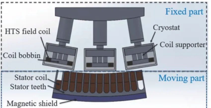
Fig 2. The cross-section view of the performance evaluation system.
B. Fundamental Structure of the 10 MW HTS Generator Fig. 1 shows the cross-section view of the 10 MW HTS generator. The generator can be divided into a rotor part and a stator part. The rotor part, which was operated at a low temperature of 30 K, consisted of a superconducting field coil, a vacuum shield, and a rotor body. The stator part consisted of a stator winding and a stator body to support the stator coil. The stator winding had double-layered and distributed three-phase winding. The stator part is operated at room temperature. The fundamental design specifications of the 10 MW superconducting generators are summarized in Table II.
The rated line-to-line voltage of the generator was 6.6 kV and the drive-train was gearless type.
Therefore, the rated speed of the rotor was 10 rpm and the torque was 10.02 MN·m. The air gap was 30 mm and the operating temperature of the rotor part was 30 K [11]-[13].
C. Detailed Design and Application Concept of the PES Fig. 2 shows the cross-section view of the PES. The PES was designed based on a 1/20 model of the full 40-pole 10 MW HTS generator. The PES consisted of three HTS coils and the corresponding armature windings. The PES was divided into a fixed part and a moving part. The fixed part consisted of a superconducting field coil, a cryostat, and a coil supporter.
The stator part consisted of the armature winding, the armature body, and a magnetic shield.
The armature winding used a double-layered, distributed three-phase winding method to reduce total harmonic distortion. One right slot and one left slot are half empty. Thus, this model can be compared to the full 40-pole 10 MW HTS generator for the magnetic flux generated between HTS coils and armature. The armature passes the three fixed HTS coils at a speed of about 3.8 m/s, which is equal to 10 rpm of the 10 MW HTS generator. The design specifications of the PES are summarized in Table III. Their rated power and line-to- line voltage were 525 kW and 330 V, respectively. In the PES in which the HTS coils are linearly arranged, the output voltage and torque correspond to the two HTS coils of the 10
MW HTS generator. The PES is effected by the magnetic fields attenuation, which causes the end effect.
In the generator, the end effect does not occur because of their cylindrical geometry that has no end in the direction of movement. However, in a linear machine such as PES, a finite part of the length passes through the magnetic field, resulting in an end effect. The end effect is caused by the attenuated magnetic field and plays an important role in the performance of the PES. Therefore, three pairs of HTS coils are required to make a pole pair.
III. SIMULATIONS AND COMPARATIVE ANALYSIS OF THE 10 MW GENERATOR AND PES
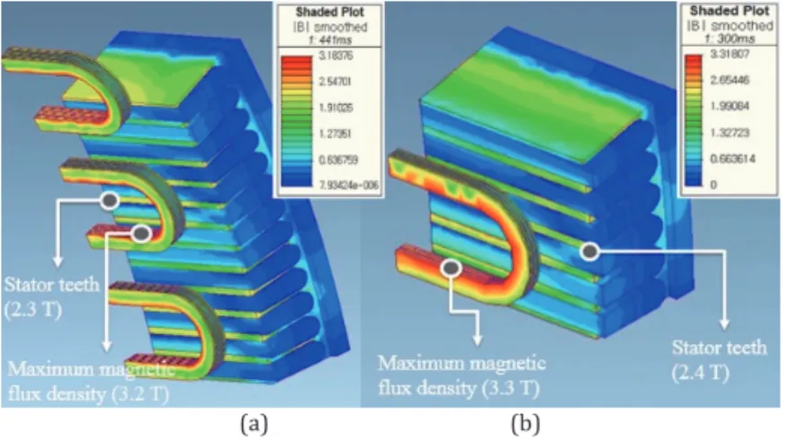
A. FEM Analysis Results of the 10 MW Generator and PES The design of the HTS generator and PES was analyzed with 3D FEM using the MagNet program. Fig. 3 illustrates the magnetic field distributions of the 10 MW HTS generator and PES. To reduce the simulation time, 1/40 model was used in 10 MW HTS generator. The maximum magnetic fields of the 10 MW HTS generator and PES were 3.3 T and 3.2 T, respectively. Fig. 4 shows the perpendicular magnetic flux density distribution of the 10 MW HTS generator and PES. The maximum perpendicular magnetic fields of the 10 MW HTS generator and PES at the HTS field coil were 2.19 T and 2.15 T. In this case, the DC field current is 253 A with 40% margin in which the current is determined by the properties of the HTS wire [14].
B. Comparison of the 10 MW Generator and PES
Fig. 5 and 6 show the torque values of the 10 MW HTS generator and PES under the full-load conditions. The rated torque values of the 10 MW HTS generator and PES were 10.02 MN·m and 501 kN·m, respectively. The torque value of the PES was 1/20 of the full 40-pole 10 MW HTS generator since the PES was simulated as a 1/20 model of the HTS
(a) (b)
Fig 3. Magnetic field distribution of the 10 MW HTS generator and the PES. (a) PES. (b) 1/40 model of 10 MW HTS generator.
(a) (b)
Fig 4. Perpendicular magnetic field distribution of the 10 MW HTS generator and the PES. (a) PES. (b) 1/40 model of 10 MW HTS generator.
HTS generator. Electromagnetic analysis results of the 10 MW HTS generator and PES were compared for magnetic field distributions, the output power, and torque values. The results of the comparison of the torque values of the 10 MW HTS generator with the PES were discussed to demonstrate the feasibility of the PES. The torque values of the 10 MW HTS generator and the PES were 10.02 MN·m and 488 kN·m, respectively. To compare the output power and torque of the PES with the generator, it can be treated the same as the one pole pair of the 10 MW HTS generator. Therefore, the PES for testing the 10 MW HTS generator can be used to test the mechanical strength of the HTS coil under high magnetic field and high torque. The critical characteristics estimation method of the 10 MW HTS generator will effectively be utilized to develop a large-scale wind power system.
II. COMPASITION OF A 10 MW HTS GENREATOR AND CONCEPT OF A PES
A. Specifications of HTS Coils for the 10 MW HTS Genrator The specifications and the dimensions of the HTS coil are
summarized in Table 1. The HTS coils consisted of racetrack- type double pancake coils. The HTS wire was coated with a flat conductive tape having a thickness of 0.15 mm and a width of 10 mm. Metallic insulation (MI) was applied to the HTS pancake coil. The MI coil was co-wound with an HTS wire and a stain-less steel tape with a thickness of 0.10 mm.
The advantages of MI coil are a low bypassing current that results in a lower charging time, and better thermal stability as well as an enhanced mechanical integrity [8][9].
In this paper, the difference between the 10 MW superconducting generator and other superconducting generators is that the module coils are adopted to a rotor part.
The HTS module coil means that each HTS coil has its own individual cryostat. The advantage of the module coils is that it can reduce the vacuum vessel, and make it easier to repair and maintain the HTS coils compared to the HTS generators which have to cool the entire rotor. The module coil consists of one cryostat, coil bobbins and supports, heat exchanger, cryo-cooler, and one HTS coil [10].
Table 1
Specifications and Dimensions of the HTS Coils for 10 MW HTS Generator
Specifications Value
Turns of field coil 260
Number of layer in HTS rotor coil 6
Operating current 253 A
Operating temperature 30 K
Width of bobbin 250 mm
Width of coil 65 mm
Effective length of coil 700 mm
Height of coil 74 mm
Total length of a 1 pole HTS wire 3.6 km Table 2
Specifications of the Designed 10 MW HTS Generator
Specifications Value
Rated output power 10 MW
Rated L-L voltage 6.6 kV
Rated armature current 918.5 A
Rotating speed 10 rpm
Rated torque 10.02 MN·m
Number of poles 40
Number of layer 6
Rated frequency 3.33 Hz
Operating temperature 30 K
Air-gap length 30 mm
Cross sectional area of YBCO wire 1.5 mm2 Table 3
Specifications of the Designed PES
Specifications Value
Rated output power 525 kW
Rated L-L voltage 330 V
Rated armature current 918.5 A
Linear speed 3.81 m/s
Rated torque 501 kN·m
Number of poles 3
Number of layer 6
Operating temperature 30 K
Air-gap length 30 mm
Fig 1. Schematic diagram of the direct-drive type SCSG wind power generation systems.
Fig 2. The cross-section view of the performance evaluation system.
B. Fundamental Structure of the 10 MW HTS Generator Fig. 1 shows the cross-section view of the 10 MW HTS generator. The generator can be divided into a rotor part and a stator part. The rotor part, which was operated at a low temperature of 30 K, consisted of a superconducting field coil, a vacuum shield, and a rotor body. The stator part consisted of a stator winding and a stator body to support the stator coil. The stator winding had double-layered and distributed three-phase winding. The stator part is operated at room temperature. The fundamental design specifications of the 10 MW superconducting generators are summarized in Table II.
The rated line-to-line voltage of the generator was 6.6 kV and the drive-train was gearless type.
Therefore, the rated speed of the rotor was 10 rpm and the torque was 10.02 MN·m. The air gap was 30 mm and the operating temperature of the rotor part was 30 K [11]-[13].
C. Detailed Design and Application Concept of the PES Fig. 2 shows the cross-section view of the PES. The PES was designed based on a 1/20 model of the full 40-pole 10 MW HTS generator. The PES consisted of three HTS coils and the corresponding armature windings. The PES was divided into a fixed part and a moving part. The fixed part consisted of a superconducting field coil, a cryostat, and a coil supporter.
The stator part consisted of the armature winding, the armature body, and a magnetic shield.
The armature winding used a double-layered, distributed three-phase winding method to reduce total harmonic distortion. One right slot and one left slot are half empty. Thus, this model can be compared to the full 40-pole 10 MW HTS generator for the magnetic flux generated between HTS coils and armature. The armature passes the three fixed HTS coils at a speed of about 3.8 m/s, which is equal to 10 rpm of the 10 MW HTS generator. The design specifications of the PES are summarized in Table III. Their rated power and line-to- line voltage were 525 kW and 330 V, respectively. In the PES in which the HTS coils are linearly arranged, the output voltage and torque correspond to the two HTS coils of the 10
MW HTS generator. The PES is effected by the magnetic fields attenuation, which causes the end effect.
In the generator, the end effect does not occur because of their cylindrical geometry that has no end in the direction of movement. However, in a linear machine such as PES, a finite part of the length passes through the magnetic field, resulting in an end effect. The end effect is caused by the attenuated magnetic field and plays an important role in the performance of the PES. Therefore, three pairs of HTS coils are required to make a pole pair.
III. SIMULATIONS AND COMPARATIVE ANALYSIS OF THE 10 MW GENERATOR AND PES
A. FEM Analysis Results of the 10 MW Generator and PES The design of the HTS generator and PES was analyzed with 3D FEM using the MagNet program. Fig. 3 illustrates the magnetic field distributions of the 10 MW HTS generator and PES. To reduce the simulation time, 1/40 model was used in 10 MW HTS generator. The maximum magnetic fields of the 10 MW HTS generator and PES were 3.3 T and 3.2 T, respectively. Fig. 4 shows the perpendicular magnetic flux density distribution of the 10 MW HTS generator and PES.
The maximum perpendicular magnetic fields of the 10 MW HTS generator and PES at the HTS field coil were 2.19 T and 2.15 T. In this case, the DC field current is 253 A with 40%
margin in which the current is determined by the properties of the HTS wire [14].
B. Comparison of the 10 MW Generator and PES
Fig. 5 and 6 show the torque values of the 10 MW HTS generator and PES under the full-load conditions. The rated torque values of the 10 MW HTS generator and PES were 10.02 MN·m and 501 kN·m, respectively. The torque value of the PES was 1/20 of the full 40-pole 10 MW HTS generator since the PES was simulated as a 1/20 model of the HTS
(a) (b)
Fig 3. Magnetic field distribution of the 10 MW HTS generator and the PES. (a) PES. (b) 1/40 model of 10 MW HTS generator.
(a) (b)
Fig 4. Perpendicular magnetic field distribution of the 10 MW HTS generator and the PES. (a) PES. (b) 1/40 model of 10 MW HTS generator.
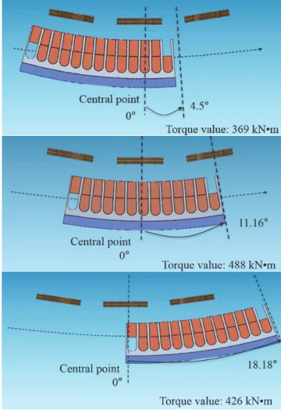
generator. The torque value of the electromagnetic analysis result of the PES is 97% of the 1/20 of the rated torque of the 10 MW HTS generator. Due to discontinuous armature winding, the torque value of the PES is considered to be 3%
less than the 10 MW HTS generator. Fig. 7 shows the position of the PES along the angle difference.
Fig. 8 shows the output voltage of the PES and 10 MW HTS generator. The rated output voltages of the 10 MW HTS generator and the PES were 6.6 kV and 330 V, respectively. In this paper, the 10 MW HTS generator was designed as an iron core type to obtain a high electromotive force.
IV. CONCLUSION
In this paper, the authors propose a method to evaluate the critical characteristics of a large-scale HTS wind turbine generator using PES. The PES consists of three HTS coils and the corresponding armature winding. The PES was designed based on a 1/20 model of the full 40-pole 10 MW HTS wind
Fig 5. Rated torque of the 10 MW HTS generator.
Fig 6. Torque analysis results of the PES.
Fig 7. Electromagnetic torque waveforms of SCSGs.
(a)
(b)
Fig 8. Rated output voltages of the 10 MW HTS generator and the PES.
(a) 10 MW HTS generator. (b) PES.
power generator. The three HTS coils are stationary and the armature passes the HTS coils at the same speed as the rotating speed of the generator. The magnetic field distributions of the 10 MW HTS generator and PES were analyzed using a 3D FEM. The 10 MW HTS generator and PES were compared focusing on the torque value, output voltage, and magnetic flux density. The torque values of the 10 MW HTS generator and PES were 10.02 MN·m and 488 kN·m, respectively. As a result, the PES generated the same output as a pole-pair of the HTS generator. Through this study, it is shown that the PES can be used to check whether the HTS coil can withstand the high torque of the large capacity HTS generator before manufacturing the wind turbines.
Therefore, it is expected that this method can be effectively used to develop large-scale HTS wind turbine generation systems.
ACKNOWLEDGEMENT
This research was supported by Korea Electric Power Corporation (Grant number:R18XA03).
REFERENCES
[1] C. Lewis, J. Muller, “A Direct Drive Wind Turbine HTS Generator,” IEEE power Engineering Society General Meeting, pp 1-8, Tampa, FL, USA, 24- 28 June 2007.BTM Consult, International Wind Energy Development:
Offshore Report 2013: BTM, 2012.
[2] B. Maples, M. M. Hand, and W. D. Musial, “Comparative assessment of direct drive high temperature superconducting generators in multi- megawatt class wind turbines,” Golden, CO: National Renewable Energy Laboratory, 2010.
[3] D. W. Hazelton, V. Selvamanickam, J. M. Duval, D. C. Larbalestier, W. D. Markiewicz, H. W. Weijers, R. L. Holtz, “Recent developments in 2G HTS coil technology,” IEEE Transactions on Applied Superconductivity, vol. 19, no. 3, pp. 2218-2222, 2009.
[4] G. Klaus, M. Wilke, J. Frauenhofer, W. Nick, H. W. Neumüller, “Design challenges and benefits of HTS synchronous machines,” IEEE Power & Energy Society General Meeting, pp. 1-8, 2007.
[5] M. Oomen, W. Herkert, D. Bayer, P. Kummeth, W. Nick, T. Arndt,
“Manufacturing and test of 2G-HTS coils for rotating machines: Challenges, conductor requirements, realization,” Physica C: Supercond., vol. 482, pp. 111–118, Nov. 2012.
[6] Hiroyuki Ohsaki, Yutaka Terao, Rashidul M. Quddes, Masaki Sekino,
“Electromagnetic Characteristics of 10 MW Class Superconducting Wind Turbine Generators,” IEEE Electrical Machine and system (ICEMS), pp.1303–1306, 2010.
[7] A. H. Selçuk, H. Kurum, “Investigation of end effects in linear induction motors by using the finite-element method,” IEEE Trans. Magn., vol. 44, no. 7, pp. 1791–1795, Jul. 2008.
[8] T. Lecrevisse, Y. Iwasa, “A (RE)BCO pancake winding with metal-as- insulation,” IEEE Trans. Appl. Supercond., vol. 26, no. 3, Apr. 2016, Art. no. 4700405.
[9] Y. Wang, et al., “Analysis and comparison between no-insulation and metallic insulation REBCO magnet for the engineering design of a 1-MW DC induction heater,” IEEE Trans. Appl. Supercond., vol. 27, no. 4, Jun. 2017, Art. no. 3700105.
[10] B. S. Go, H. J. Sung, M. Park, I. K. Yu, “Structural design of a module coil for a 12-MW class HTS generator for wind turbine,” IEEE Trans. Appl. Supercond., vol. 27, no. 4, Jun. 2017, Art. no. 5202405.
[11] D. David, “Development of MgB2 superconductor wire and coils for practical applications at Hyper Tech Research,” in Proc. 2013 CEC/Int. Cryogen. Mater. Conf., Anchorage, AK, USA, Jun. 2013.
[12] D. W. Hazelton, “Applications using superpower 2G HTS conductor,” in Proc. 2011 CEC/Int. Cryogen. Mater. Conf., Spokane, WA, USA, Jun. 2011. [13] W. Stautner, et al., “Large scale superconducting wind turbine cooling,” IEEE Trans. Appl. Supercond., vol. 23, no. 3, Jun. 2013, Art. no. 5200804. [14] H. J. Sung, et al., “Practical design of a 10 MW superconducting wind power generator considering weight issue,” IEEE Trans. Appl. Supercond., vol. 23, no. 3, Jun. 2013, Art. no. 5201805.
generator. The torque value of the electromagnetic analysis result of the PES is 97% of the 1/20 of the rated torque of the 10 MW HTS generator. Due to discontinuous armature winding, the torque value of the PES is considered to be 3%
less than the 10 MW HTS generator. Fig. 7 shows the position of the PES along the angle difference.
Fig. 8 shows the output voltage of the PES and 10 MW HTS generator. The rated output voltages of the 10 MW HTS generator and the PES were 6.6 kV and 330 V, respectively. In this paper, the 10 MW HTS generator was designed as an iron core type to obtain a high electromotive force.
IV. CONCLUSION
In this paper, the authors propose a method to evaluate the critical characteristics of a large-scale HTS wind turbine generator using PES. The PES consists of three HTS coils and the corresponding armature winding. The PES was designed based on a 1/20 model of the full 40-pole 10 MW HTS wind
Fig 5. Rated torque of the 10 MW HTS generator.
Fig 6. Torque analysis results of the PES.
Fig 7. Electromagnetic torque waveforms of SCSGs.
(a)
(b)
Fig 8. Rated output voltages of the 10 MW HTS generator and the PES.
(a) 10 MW HTS generator. (b) PES.
power generator. The three HTS coils are stationary and the armature passes the HTS coils at the same speed as the rotating speed of the generator. The magnetic field distributions of the 10 MW HTS generator and PES were analyzed using a 3D FEM. The 10 MW HTS generator and PES were compared focusing on the torque value, output voltage, and magnetic flux density. The torque values of the 10 MW HTS generator and PES were 10.02 MN·m and 488 kN·m, respectively. As a result, the PES generated the same output as a pole-pair of the HTS generator. Through this study, it is shown that the PES can be used to check whether the HTS coil can withstand the high torque of the large capacity HTS generator before manufacturing the wind turbines.
Therefore, it is expected that this method can be effectively used to develop large-scale HTS wind turbine generation systems.
ACKNOWLEDGEMENT
This research was supported by Korea Electric Power Corporation (Grant number:R18XA03).
REFERENCES
[1] C. Lewis, J. Muller, “A Direct Drive Wind Turbine HTS Generator,” IEEE power Engineering Society General Meeting, pp 1-8, Tampa, FL, USA, 24- 28 June 2007.BTM Consult, International Wind Energy Development:
Offshore Report 2013: BTM, 2012.
[2] B. Maples, M. M. Hand, and W. D. Musial, “Comparative assessment of direct drive high temperature superconducting generators in multi- megawatt class wind turbines,” Golden, CO: National Renewable Energy Laboratory, 2010.
[3] D. W. Hazelton, V. Selvamanickam, J. M. Duval, D. C. Larbalestier, W. D.
Markiewicz, H. W. Weijers, R. L. Holtz, “Recent developments in 2G HTS coil technology,” IEEE Transactions on Applied Superconductivity, vol.
19, no. 3, pp. 2218-2222, 2009.
[4] G. Klaus, M. Wilke, J. Frauenhofer, W. Nick, H. W. Neumüller, “Design challenges and benefits of HTS synchronous machines,” IEEE Power &
Energy Society General Meeting, pp. 1-8, 2007.
[5] M. Oomen, W. Herkert, D. Bayer, P. Kummeth, W. Nick, T. Arndt,
“Manufacturing and test of 2G-HTS coils for rotating machines:
Challenges, conductor requirements, realization,” Physica C:
Supercond., vol. 482, pp. 111–118, Nov. 2012.
[6] Hiroyuki Ohsaki, Yutaka Terao, Rashidul M. Quddes, Masaki Sekino,
“Electromagnetic Characteristics of 10 MW Class Superconducting Wind Turbine Generators,” IEEE Electrical Machine and system (ICEMS), pp.1303–1306, 2010.
[7] A. H. Selçuk, H. Kurum, “Investigation of end effects in linear induction motors by using the finite-element method,” IEEE Trans. Magn., vol. 44, no. 7, pp. 1791–1795, Jul. 2008.
[8] T. Lecrevisse, Y. Iwasa, “A (RE)BCO pancake winding with metal-as- insulation,” IEEE Trans. Appl. Supercond., vol. 26, no. 3, Apr. 2016, Art.
no. 4700405.
[9] Y. Wang, et al., “Analysis and comparison between no-insulation and metallic insulation REBCO magnet for the engineering design of a 1-MW DC induction heater,” IEEE Trans. Appl. Supercond., vol. 27, no. 4, Jun.
2017, Art. no. 3700105.
[10] B. S. Go, H. J. Sung, M. Park, I. K. Yu, “Structural design of a module coil for a 12-MW class HTS generator for wind turbine,” IEEE Trans. Appl.
Supercond., vol. 27, no. 4, Jun. 2017, Art. no. 5202405.
[11] D. David, “Development of MgB2 superconductor wire and coils for practical applications at Hyper Tech Research,” in Proc. 2013 CEC/Int.
Cryogen. Mater. Conf., Anchorage, AK, USA, Jun. 2013.
[12] D. W. Hazelton, “Applications using superpower 2G HTS conductor,” in Proc. 2011 CEC/Int. Cryogen. Mater. Conf., Spokane, WA, USA, Jun. 2011.
[13] W. Stautner, et al., “Large scale superconducting wind turbine cooling,”
IEEE Trans. Appl. Supercond., vol. 23, no. 3, Jun. 2013, Art. no. 5200804.
[14] H. J. Sung, et al., “Practical design of a 10 MW superconducting wind power generator considering weight issue,” IEEE Trans. Appl.
Supercond., vol. 23, no. 3, Jun. 2013, Art. no. 5201805.