Progress in Superconductivity and Cryogenics
Vol.15, No.3, (2013), pp.29~34 http://dx.doi.org/10.9714/psac.2013.15.3.029
```
1. INTRODUCTION
Currently, the world has been focusing on the development of green energy technologies such as a solar power, wind power, biomass, and hydropower. Among them, the wind power is greater economic efficiency than others green energy because of high energy generation rate per unit area. Also, the wind power is little impact on the environmental aspect because of using pollution-free and infinitely wind. It could be possible to make more effective use of the homeland.
The current global trends of wind power are a development of large capacity turbine and construction of offshore wind farm. 10 MW class wind power generator demand is increasing in order to make the GW class offshore wind farm.
Nevertheless, to make progress of these trends must break through some technical limits such as drive-train failure or heavy weight which could bring about the serious system problem in over 6 MW class wind turbine. Superconducting technology using the high temperature superconductor is an effective way to overcome these limitations. The generator using the HTS field coil has some specific advantages as follows: (a) The field coil of the rotor using the HTS wire with the high current density can generate high magnetic field.
Therefore, If the same capacity superconducting generator is capable of reduction about 33% of the weight and 40% of the volume of generator compared with conventional direct-driven permanent magnet synchronous generator (PMSG) and (b) because the use of HTS wire with zero resistance and the air- core stator manufactured by non-magnetic materials are capable of reducing the excitation loss and iron loss, respectively, the machine losses can be reduced by 60%
compared to conventional direct-driven PMSG.
Therefore, generator efficiency can be increased. Also, (C) because of air-core stator with high dielectric strength, the higher terminal voltage can be used such as 3 and 6 kV.
Due to these advantages of performance improvement, in the future, mainstream of wind generator is a HTS generator in the global wind power market. However, study on the design of over 10 MW class HTS wind generator is rare in the world. Therefore, this paper introduces electromagnetic design processes of 10 MW class HTS generator for offshore wind turbine.
To design of 10 MW class HTS generator, the design process with several different approaches will be introduced as follows.
First of all, design parameter focuses on the number of rotor poles. Whereas the HTS field coil can generate high magnetic flux, the price competitiveness is relatively low as compare to conventional generator with the field coil fabricated by copper wire. Consequently, in case of designing the HTS wind generator, minimizing the amount of HTS wire used to fabricate the field coil is one of the key parameters.
Secondly, operating current selection of the HTS field coil is important. The optimal operating current can minimize the decrease of the critical current density generated due to the increase of the self-field around the HTS wire. Therefore, the operating current of the HTS field coil can be adapted as a design parameter.
Last but not least, the terminal voltage of the stator is design parameter for the superconducting wind generators.
In this paper, after achievements the basic design models of the HTS generator by using the two-dimensional (2D) numerical analysis, three-dimensional finite element analysis (3D FEA) for the electromagnetic design and optimization of the HTS generator was carried out.
Electromagnetic design of 10 MW class superconducting wind turbine using 2G HTS wire
J. H. Kim and H. M. Kim* Jeju National University, Jeju
(Received 2 September 2013; revised or reviewed 29 September 2013; accepted 30 September 2013)
Abstract
This paper introduces design processes of 10 MW class superconducting generator for wind Turbine. Superconducting generator can produce 5 times stronger magnetic field than permanent magnet at least, which enables large scale wind turbine to function as a lighter, smaller and more highly efficient system. These processes are targeted for higher efficiency and shorter high temperature superconductor (HTS) wires to fabricate 10 MW class superconducting generator. Three different approaches will be described in these design processes. First design process focuses on the number of rotor poles. Secondly, 270 and 360 A operating current of superconducting field coil can be adapted as a design parameter in this process. Lastly, 3 and 6 kV line to line voltage of stator coil will be used to design 10 MW class superconducting generator.
Keywords : HTS wire, magnetic field, superconducting generator, wind turbine
* Corresponding author: [email protected]
Electromagnetic design of 10 MW class superconducting wind turbine using 2G HTS wire
2.DESIGN OF 10MW CLASS HTS GENERATOR TABLEI
BASIC DESIGN MODELS OF THE 10MW CLASS HTS
WIND GENERATOR.
Parameter Model
I Model
II Model
III Model IV
Rated output power (MW) 10 10 10 10
Rated rotation speed (rpm) 10 10 10 10
Rotor poles 6 6 12 12
Operating current (A) 270 360 270 360
Rated output voltage (kV) 3 6 3 6
HTS wire usage (km) 210 213.3 493.8 234.8 Efficiency (%) 86.08 91.47 85.05 79.3 Synchronous reactance 0.2 0.2 0.2 0.2
Stator current
density(A/mm2) 12 12 12 12
Fig. 1. Schematic view of the final conceptual design of 10 MW class HTS wind generator.
Fig. 2. Change of the size of outer diameter and weight of the 10 MW class HTS wind generator.
TABLEII
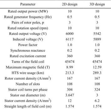
COMPARISON OF THE SPECIFICATIONS FOR 2D DESIGN AND 3D DESIGN.
Parameter 2D design 3D design
Rated output power (MW) 10 10
Rated generator frequency (Hz) 0.5 0.5
Pairs of rotor poles, p 3 3
Rated rotation speed (rpm) 10 10
Rated output voltage (V) 6000 5542
Induced voltage (V) 6117 5889
Power factor 1.0 1.0
Synchronous reactance 0.2 0.2
Rated excitation current 360 360
Turns of the field coil 45474 45474
Maximum magnetic field (T) 8.99 12.59
HTS wire usage (km) 213.3 289.3
Rotor current density (A/mm2) 167 167
Number of slots 108 108
Stator coil turns per phase 304 324
Stator out diameter (m) 3.647 3
Stator current density (A/mm2) 12 6.2 Straight length of field coil (m) 1.574 1.574
To design the 10 MW class HTS generator, this paper proposes a design process for large scale superconducting wind turbine using 2D numerical analysis method and 3D FEA. The design goal consists of the HTS wire length of field coil, machine efficiency and machine volume. Table I shows the basic design models considered 3 kinds of design parameter such as number of poles, operating current of the HTS field coil, and rated output voltage at the stator. There are four kinds of models to design the 10 MW class HTS generators for wind power. We chose the model II which is the highest efficiency whereas minimizing the HTS wire usage to fabricate 10 MW class HTS generator [1], [2].
Fig. 1 and Table II show the schematic view of the final conceptual design and the differences between 2D and 3D design model of 10 MW class HTS wind generator, respectively. Comparing the differences of 2D and 3D design parameters, the two different features in the design parameters of the 10 MW class HTS generators are as follows; (a) the first one is the maximum magnetic flux density between the 2D and 3D design models. In case of 2D design model, maximum magnetic field on the HTS field coil is around 8.99 T at the straight parts of the coil.
On the other hand, in case of the 3D FEA design, the value of maximum magnetic field reaches about 12.59 T at curvature parts of the HTS field coil. Because the HTS field coil is manufactured with a race-track shape, the distribution of magnetic field density varies at the straight and curvature parts of the coil [3]. Maximum magnetic flux density in the perpendicular direction can affect to the HTS field coil performance, so the calculation of magnetic flux density is important and (b) the other is the change of the size of the generator outer diameter. From the 2D design results, the size of the stator outer diameter is 3.647 m when generating the maximum magnetic flux density with 1.0 T on the mechanical shield region. According to the 3D FEA design results, because electromagnetic analysis is 30
J. H. Kim and H. M. Kim
analyzed with one sixth of full analysis model considering the symmetry, maximum magnetic field is distributed on the edge of analysis model depending on the position of the armature and field coils.
The magnetic flux density on the mechanical shield is less than 2D design results. Therefore, the thickness reduction of mechanical outer diameter is about 0.647 m.
Finally, the outer diameter of mechanical shield could be reduced to 3 m as shown in Fig. 2. The initial design values of the weight and volume were 87.946 ton and 26.729 m3, respectively. However, as the result of reducing the mechanical shield thickness, at the same time, the reduction of weight and volume of 10 MW class HTS generator are 41.64 ton and 15.76 m3, respectively.
The HTS generator is mainly composed of two parts: the stationary part and the rotating part. The HTS field coil installed in the rotor is to produce high magnetic flux density. The magnetic flux density generated from rotor is combined to the rotating magnetic flux achieved from stator winding to facilitate the HTS generator. The rotor of 10 MW class superconducting generator is composed of 6 poles. Each pole consists of race-track type 1 single-pancake (SP) and 4 double-pancake (DP) coils. The
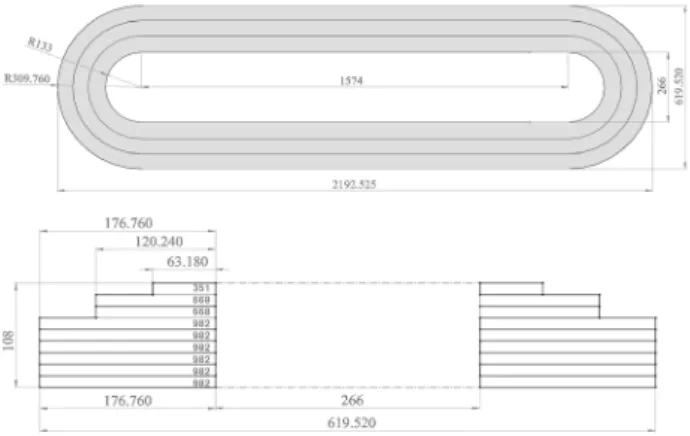
Fig. 3. Schematic view of a race-track type DP field coil for 10 MW class HTS wind generator, unit: mm.
Fig. 4. In-field property of second generation HTS wire under perpendicular field.
size of width and length of straight parts in the HTS field coil has 619 and 1574 mm. The number of turns at each layer of the HTS field winding is 351 turns in first layer, 668 turns in second and third layer, and 982 turns in the other coils as shown in Fig. 3.
This paper focuses on the second generation (2G) HTS wire which was used for the field coil of 10 MW class HTS generator. The width and thickness of the 2G HTS wire have 12.0 and 0.2 mm, respectively and the rotor current density will be able to supply around 167 A/mm2.
Fig. 4 shows the in-field property of 2G HTS wire used to design the 10 MW class HTS generators. These curves present the critical current (IC) properties related to various cooling temperatures and magnetic flux density which affects 2G HTS wire located in the perpendicular direction [4]. In general, in case of 2G HTS wire, performance of 2G wire is further reduced by the magnetic flux density in the perpendicular direction than the magnetic flux density in the parallel direction.
The 2G HTS wire manufactured by Superpower Inc. in Japan used in this design has 130 A critical current at width of 4 mm, the cooling temperature of 77 K, and the self-field condition. When the width of 2G HTS wire used for the 10 MW class HTS generator design is 12 mm, the critical current of the HTS wire for the field coil reaches almost three times more critical current than the 2G wire with 4 mm width. When considering maximum magnetic field of 6.4 T in the HTS field coil, the critical current of the 2G HTS wire comes to be about 507 A at the cooling temperature of 22 K and the self-field condition. This critical current value is sufficient to design 10 MW class HTS generator. The operating current value to charge the HTS field coil is determined at 360 A. This value as regarding to consider the stability of the HTS field coil operated in transient state reaches almost 71% of the critical current.
To eliminate the grid-side step-up transformer, which is desirable for both on-shore and offshore wind turbines, the converter modules are cascaded to achieve medium voltage output (6 kV~33 kV). Therefore, the rated output voltage of the stator is designed to 6 kV [5].
The stator is designed by an air-core stator manufactured by FRP (fiber reinforced plastics) and the total number of slots is 108. Two layer stator windings are wound by conventional copper conductors such as Litz wire in such way that full pitch winding. In the stator coil, because the current density of forced water cooling for conventional rotating machine is greater than 10 A/mm2, the current density of 12 A/mm2 is selected as the initial 2D design parameters.
Also, in case of 3D design, the number of stator winding per phase which is wound in stator slots should be an integer multiple, so 304 turns which are the number of stator winding per phase of 2D design proposal are changed to 324 turns. Therefore, the current density of 12/mm2 to charge three-phase windings is reduced to 6.2/mm2. 31
Electromagnetic design of 10 MW class superconducting wind turbine using 2G HTS wire
3. ANALYSIS OF 10MW CLASS HTSGENERATOR The magnetic flux density values generated from the HTS field coils are calculated at each layer of the race- track type SP coils. It is important factor to influence at the critical current magnitude of 2G HTS wire.
When charging only the HTS field coil, 7955 kJ magnetic energy is stored into the magnetic circuit in accordance with analysis region. The self-inductance value of the HTS field coil calculated when charging only the HTS field coil is 122.8 H.
Compared with conventional rotating machine, the field coil of superconducting machine is manufactured by HTS wire. Therefore, investigation on the in-field property of the HTS field coil which has the anisotropic JC-B characteristics should be essentially calculatedby 3D FEA.
The anisotropic JC-B characteristics of the HTS wire vary as concerning the direction of magnetic flux density injected at the 2G HTS wire surface [6].
Critical current density (JC) which is charged on the HTS field coil depends on the magnetic flux density of the perpendicular direction acting winding surface which exists at the parts of the straight and curvature of the HTS field coil. Also, Lorentz force generated in the 2G HTS field coil might be affected by the magnetic flux density of the parallel direction of the HTS field coil.
Fig. 5. The magnetic flux density distribution of the perpendicular direction on the central section of (a) the straight parts and (b) the curvature parts of the HTS field coil.
Fig. 6. The magnetic flux density distribution of the parallel direction on the central section of (a) the straight parts and (b) the curvature parts of the HTS field coil.
Fig. 5 and 6 present a 3D magnetic field distribution calculated from the 3D FEA. According to 3D FEA, when charging the field current of 360 A, the maximum magnetic flux density of the perpendicular direction at the central section of the straight parts of the race-track type DP coils reaches 7.3 T. The maximum value as shown in Fig. 5-(a) appeared at 9th SP coil located in the HTS field coil. The maximum magnetic flux density of the perpendicular direction at the curvature part which is located at 1st SP coil is around 6.4 T as shown in Fig. 5-(b).
We also investigated the magnetic flux density of the parallel direction over the HTS field coil by using 3D FEA method. Fig. 6 presents the magnetic field distribution of the parallel direction on the central section of the straight parts of the HTS field coil when only the HTS winding is charged. The maximum magnetic flux density values on the central sections of the straight and the curvature parts of the HTS field coil are 10.88 and 12.61 T, respectively as shown in Fig. 5.
TABLEIII
MAXIMUM MAGNETIC FLUX DENSITY OF THE PERPENDICULAR AND PARALLEL DIRECTIONS IN EACH LAYER OF THE FIELD COIL
Straight parts Curvature parts
Mag B[T] B⊥[T] B//[T] B⊥[T] B//[T]
1st 11.41 6.37 .8 6.4 12.61
2nd 12 6.18 10.35 6.19 11.79
3rd 12.36 4.5 10.7 4.5 12.3
4th 12.56 4.38 10.87 4.43 12.56
5th 12.5 2.3 10.88 2.48 12.61
6th 12.59 2.19 10.88 1.57 12.61
7th 12.47 3.8 10.73 2.98 12.4
8th 12.17 5.51 10.39 4.2 11.96
9th 11.65 7.3 9.03 5.86 11.2
∗ Mag B, B⊥ and B// present magnitude of the maximum magnetic flux density, maximum perpendicular magnetic flux density, maximum parallel magnetic flux density, respectively
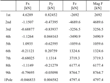
TABLEIV
LORENTZ FORCE VALUES AFFECTED IN EACH LAYER OF HTS FIELD COIL
[kN] Fx Fy
[kN] Fz
[kN] Mag F
[kN]
1st 4.6289 0.82452 -2692 2692
2nd -1.1507 -0.47395 -4689.6 4689.6
3rd -0.68877 -0.83937 -3256.5 3256.5
4th -1.1264 0.044163 -3490.9 3490.9
5th 1.0935 -0.62595 -1059.6 1059.6
6th -0.21121 0.20759 1324.6 1324.6
7th -0.68025 1.1314 3719.3 3719.3
8th -1.1149 -0.21279 6177.4 6177.4
9th -0.79695 -0.05098 8764.7 8764.7
1Pole -0.046833 0.004582 4797.4 4797.4
32
J. H. Kim and H. M. Kim
Fig. 7. The magnetic flux density distribution of 10 MW class HTS wind generator at the steady state operation.
Table III and Table IV show the maximum magnetic flux density and Lorentz force in each layer of the HTS field coil. Lorentz force acting on the HTS field coil depends on the magnetic flux density of the parallel direction generated by charging current of HTS field coil. Maximum Lorentz Forces working on the HTS field coil which is installed on one rotating pole are 4.6289 (Fx), 1.1314 (Fy), and 8764.7 (Fz) kN at the 1st, 7th, and 9th SP, respectively. The maximum mechanical stress value on the HTS field coil is 464.03 MPa.
The magnetic flux density distribution of 10 MW class HTS wind generator at the steady state operation (field current of 360A and rotation speed of 10 rpm) is shown in Fig. 7. The maximum magnetic flux density is about 12.3 T at the curvature parts of HTS coils.
The maximum magnetic flux density of the radial component (Br) at the central points of double-layer armature windings in circumferential direction that is directly related to the performance of the HTS generator and calculated from the 3D FEA is approximately 2.5 T.
Because the performance of the rotating machine is proportional to Br and shape in the air gap, the value of the Br, air-gap size and shape is very important to design HTS generator [7].
The air-gap size of superconducting generator is larger than conventional machine because of requirements of the damper shield and thermal insulation layer. Magnitude of air-gap length of the superconducting generators reaches about 50−100mm. Therefore, the total linkage flux on the central points of the stator windings is decreased. Such decrement of the linkage flux can be compensated by generating very high magnetic flux from the HTS field coil.
Therefore, the size of damper and insulation layer thickness is important design factors to increase the linkage flux at the armature windings.
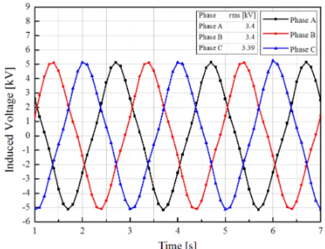
Fig. 8 presents the induced voltage at the three-phase armature winding during the time of one rotation (6 s). The root mean square (RMS) value of the induced voltage through 2D numerical design is 3532 V. But, as the results of 3D design through FEA, induced voltage is reduced to 3401 V. Although the number of stator winding per phase is increased from 304 to 324 turns, in case of 3D design, because linkage flux in the air-gap of the stator coils seems
Fig. 8. The induced voltage waveform at the three-phase armature winding.
to decrease due to the leakage flux occurs at the end of armature coils, the value of the induced voltage is likely to decline.
4. Conclusions
This paper has discussed practical considerations related to suitable designs of 10 MW class HTS generator built with 2G HTS tape in the field coil and has explained the engineering parameters for electromagnetic and mechanical requirements that need to be made.
In case of the 2G HTS wire, when decreasing the cooling temperature of HTS field coil below 22 K, it can be suitable to fabricate the HTS field coil as a conductor to manufacture the 10 MW HTS generator for wind power in economic aspects of the system. The consuming length of 2G HTS wire used for one pole manufacture is about 48.2 km. To fabricate all the HTS field coils installed on the 6 poles for 10 MW class HTS generator, 2G HTS wire length is to reach around 289.3 km long length.
In this paper, because minimizing 2G HTS wire length, weight and volume of generator is the main purpose for designing, design proposal with low system efficiency of 92% due to copper loss of 929 kW was adopted. We will be conducting the additional study to meet this paper’s purpose and efficiency.
Still, these results are quite useful to research engineers, academic researchers who are in charge of the development of the large scale HTS generator for wind power.
.
ACKNOWLEDGMENT
This work was supported by the International Collaborative R&D Program and the Power Generation &
Electricity Delivery of the Korea Institute of Energy Technology Evaluation and Planning (KETEP) grant funded by the Korea government Ministry of Trade, industry & Energy (20118520020020), (20113020020020).
33
Electromagnetic design of 10 MW class superconducting wind turbine using 2G HTS wire
REFERENCES
[1] H. M. Jang, I. Muta, T. Hoshino, T. Nakamura, S. W. Kim, M. H.
Sohn, Y. K. Kwon, and K. S. Ryu, “Design and electrical characteristics analysis of 100 HP HTS synchronous motor in 21st century frontier project,” IEEE Trans. Appl. Supercond., vol. 12, no.
2, pp. 2197-2200, 2003.
[2] S. K. Baik, M. H. Sohn, S. W. Kim, E. Y. Lee, and Y. K. Kwon, "A 100 HP HTS motor design and the performance analysis," Journal of the Korea Institute of Applied Superconductivity and Cryogenics, vol. 4, no. 2, pp. 31-37, 2002.
[3] S.B. Kim, T. kadota, J.H. Joo, H. Sano, S. Murase, S.H. Lee, J.P.
Hong, H.M. Kim, Y.K. Kwon, Y.S. Jo, “A study on electromagnetic and mechanical characteristics of the field coil in HTS motor,”
Physica C , vol. 470, pp. 1756-1762, 2010.
[4] Drew W. Hazelton, “Applications using Superpower 2G HTS conductor,” 2011 CEC/ICMC, Spokane, WA, Jun., 2011.
[5] Xibo Yuan, Yongdong Li, Jianyun Chai, “A transformerless modular permanent magnet wind generator system with minimum generator coils,” Applied Power Electronics Conference and Exposition (APEC), 2010 Twenty-Fifth Annual IEEE, pp.
2104-2110, 2010.
[6] H. Ohsaki, Y. Terao, R.M. Quddes, M. Sekino, “Electromagnetic Characteristics of 10 MW Class Superconducting Wind Turbine Generators,” International Conference on Electrical Machines and Systems , pp. 1303-1306, Incheon, 2010.
[7] J.H. Kim, C.-K. Jwa, Y.S. Jo, S.K. Baik, Y.K. Kwon, H.M. Kim,
“Conceptual Design of a Field Coil for 5 MW HTS Synchronous Machine,” Journal of Superconductivity and Novel Magnetism, vol.
26, no. 4, pp. 1247-1251, 2013.
34