Manuscript received August 30, 2019, Accepted October 4, 2019
1 KEPCO Research Institute, Korea Electric Power Corporation, 105 Munji-ro Yuseong-gu, Daejeon 34056, Republic of Korea
2 Department of Electrical Engineering, Changwon National University, Changwon 641-773, Republic of Kore
Comparative Analysis of 10 MW Superconducting Wind Power Generators with Three-phase and Nine-phase Armature Windings
Taewon Kim
1, Sang-Kyun Woo
1†, Hae-Jin Sung
2††Abstract
When referring to weight, volume, and efficiency, a SuperConducting Synchronous Generator (SCSG) is definitely superior to conventional generators as a large-scale wind power generation system. The SCSG is connected to a full power converter that transmits the energy from the SCSG to the power grid. To reduce the current stress and system cost, the SCSG which has nine- phase armature windings with three converters is used. This paper deals with a comparative analysis of 10 MW superconducting wind power generators with three-phase and nine-phase armature windings. The stator windings of SCSGs are of various types.
Using the finite element method, SCSGs are analyzed and compared in terms of the weight and volume of SCSGs, the total length of the superconducting wire, harmonics, torque performance, and efficiency. The analyzed results will be effectively utilized to design large-scale superconducting generators for wind power generation systems.
Keywords: Direct-Driven, Generators, High-Temperature Superconductors, Wind Power Generation
I. INTRODUCTION
Offshore wind power capacity contributed 470 MW to worldwide installations of wind power in 2011. The total installed capacity of offshore wind power from January of 2012 to October of 2012 was 1,314 MW. Offshore wind farms are currently under construction in Belgium, Denmark, Germany, the UK, China, Korea, and Japan with a total expected capacity upon completion of nearly 100 GW. The average annual growth rate for new installations is expected to be 81.8 % until 2016 [1].
A direct-drive type SuperConducting Synchronous Generator (SCSG) has a smaller physical size and a higher power density per volume ratio than conventional generators [2][3]. Because of these advantages, the SCSG is becoming an interesting solution to the need for a large scale wind turbine.
A full-scale frequency converter is connected between the generator and grid. The larger the capacity of the power converter is, the higher the cost and power loss in the power electronic devises because all the generated power must pass
through the power converter. To reduce these drawbacks, generators with nine-phase armature windings with three converters are adopted [4]-[6].
In this paper, 10 MW SCSGs are compared in terms of their three-phase and nine-phase armature windings. The stator winding types of SCSGs are used in this comparison, such as Short-pitch Concentrated Winding (SCW), Full-pitch Concentrated Winding (FCW), Short-pitch Distributed Winding (SDW), and Full-pitch Distributed Winding (FDW).
These SCSGs are analyzed by using a 3D Finite Elements Method (FEM) program.
As a result, harmonics of the three-phase SCSG with SDW
and FDW decrease and the nine-phase SCSG is heavier and
larger than the three-phase SCSG. On the other hand, the
torque ripples of nine-phase SCSGs are lower than three-
phase SCSGs, and the efficiency of the nine-phase SCSG with
FDW is higher than that of the three-phase SCSG. The
analyzed results will be effectively utilized to determine the
most efficient stator winding type for large-scale
superconducting wind power generators.
II. DESIGN SPECIFICATIONS OF 10 MW SCSGS The schematic diagram of the three-phase and nine- phase SCSG wind power generation systems is shown in Fig.
1. The full-scale frequency converter consists of a Pulse Width Modulation (PWM) rectifier, which permits control of the phase current of the generator, and a PWM inverter for grid connection via a transformer.
The full-scale frequency converter of the three-phase SCSG transmits all the power generated at the SCSG to the power grid. The drawbacks of this system are the current stress caused by the high rated armature current and the cost of the high capacity converter. To improve these drawbacks, a nine-phase SCSG wind power generation system is applied.
The nine-phase SCSG has the three sets of three-phase armature windings, which are separated electrically. Each set of armature windings is connected to the full-scale frequency
converter. Total three converters are used in the nine-phase SCSG for the wind power generation system. Therefore, the power of each converter is one third of the generator power because the rated armature current is decreased by one third.
This system can reduce the current stress and cost of the converter. However, problems such as technical challenges and the voltage unbalance of each converter occur.
Fig. 2 depicts the configuration of the SCSG [3]. The rotor part consists of High Temperature Superconducting (HTS) coils, the rotor body, and the vacuum vessel. The stator part is comprised of the copper coils, stator teeth, and the magnetic shield.
The HTS rotor coils and rotor body supporting the HTS coil are cooled in the vacuum vessel at 20 K. A nonmagnetic material is used for the rotor body, vacuum vessel, and stator teeth. The magnetic shield uses laminated silicon steel. The SCSG is not equipped with a damper winding. If the SCSG is connected to the full-scale frequency converter, which provides a variable stator frequency according to the actual rotor speed, no relative movement between the stator and rotor field will exist [7].
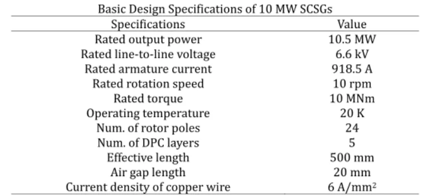
The basic design specifications of SCSGs in these wind power systems are shown in Table 1. The drive-train of the
Fig 1. Schematic diagram of the direct-drive type SCSG wind power generation systems.
Fig 2. Configuration of the 10 MW SCSG.
Table 1
Basic Design Specifications of 10 MW SCSGs
Specifications Value
Rated output power 10.5 MW
Rated line-to-line voltage 6.6 kV
Rated armature current 918.5 A
Rated rotation speed 10 rpm
Rated torque 10 MNm
Operating temperature 20 K
Num. of rotor poles 24
Num. of DPC layers 5
Effective length 500 mm
Air gap length 20 mm
Current density of copper wire 6 A/mm2
Table 2
Control Parameters of Three-phase and Nine-phase 10 MW SCSGs Three-phase SCSGs
Stator winding types SCW FCW SDW FDW
Turns of DPCs 1350 1260 1287 1260
Operating current (A) 106 106 106 106
Num. of stator slots 72 72 144 144
Turns of stator coils 50 50 25 25
Nine-phase SCSGs
Stator winding types SCW FCW SDW FDW
Turns of DPCs 1800 1780 1800 1780
Operating current (A) 102 102 102 102
Num. of stator slots 216 216 432 432
Turns of stator coils 50 50 25 25
Table 3
THD Values of Three-phase SCSGs
Stator winding types SCW FCW SDW FDW
THD (%) 8.1 8.8 4.3 4.9
generator is of the direct-drive type, and the space factors of the rotor and stator coils are 1 and 0.5, respectively. The rotor coil is a racetrack type Double Pancake Coil (DPC), and it uses 0.1 mm thick and 4 mm wide of the HTS wire. The thickness of the electrical insulation tape is 0.025 mm. Table 2 represents the control parameters of three-phase and nine- phase SCSGs. The control parameters are changed to generate the rated line-to-line voltage of each SCSG, and the operating currents apply 20 % safety margin.
III. ARMATURE WINDINGS
A. Three-Phase Armature Winding
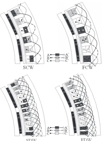
Fig. 3 shows the winding diagrams of three-phase SCSGs, including the armature windings such as SCW, FCW, SDW, and FDW. These SCSGs have three-phase Electro Motive Force (EMF) waveforms with each 120 degree phase shift.
The stator winding types are divided into a single layer and a double layer winding. The single layer winding has one coil side per slot, while the double layer winding has two coil sides per slot. The double layer winding can be classified as a full-pitch or a short-pitch winding.
When the two coil sides of the stator coil are 180 electrical space degrees apart, the winding is the full-pitch
winding, such as FCW or FDW. When the two coil sides of the stator coil are less than 180 electrical space degrees apart, the winding is the short-pitch winding, such as SCW or SDW.
In the case of SCW and FCW, the number of slots is 72 due to the concentrated winding i.e. one slot per pole per phase.
In SCSGs with SDW and FDW, the number of slots is 144 due to the distributed winding, with two slots per pole per phase.
The harmonic amplitudes of three-phase SCSGs with a fundamental frequency of 2 Hz are illustrated in Fig. 4. Table 3 shows the Total Harmonic Distortion (THD) values of three- phase SCSGs. The THD of a synchronous machine must be less
Fig 3. Winding diagrams of three-phase SCSGs.
Fig 4. Harmonic spectrum of three-phase SCSGs.
Fig 5. Winding diagrams of nine-phase SCSGs
than 5 % [8]. Therefore, SCSGs with SDW and FDW are suited to standard IEEE conditions.
B. Nine-Phase Armature Winding
Fig. 5 depicts the winding diagrams of nine-phase SCSGs which have three sets of three-phase armature windings.
Each set is spatially shifted by 40 electric degrees.
For nine-phase SCSGs with concentrated windings, SCW and FCW, the number of slots is three times that of the three- phase SCSG with concentrated windings. In the case of SDW and FDW, the number of slots is 432 due to the distributed winding with two slots per pole per phase. Fig. 6 shows the harmonic spectrum of the nine-phase SCSGs, and the THD values are shown in Table 4. SCSG with SDW is appropriate.
IV. SIMULATION AND COMPARATIVE ANALYSIS The torque ripple, which is related with the vibrations and noise of the generator, greatly depends on the stator winding types. Fig. 7 shows the electromagnetic torque waveforms of SCSGs under rated load conditions. Comparing stator winding types, the value of the torque ripple in the
three-phase SCSG with SCW is 4.8 % higher than the three- phase SCSG with SDW, and nine-phase SCSGs cause lower torque ripples than three-phase SCSGs because the torque ripples produced by the nine-phase SCSGs are compensated with each other [4].
The values of the maximum magnetic field and perpendicular magnetic field of SCSGs are illustrated in Fig. 8, and Table 5 represents the losses and efficiencies of SCSGs.
The efficiencies of SCSGs are 99 % similar to one another. The efficiency of the nine-phase SCSG with FDW is the highest because its rated armature current is one-third that of the three-phase SCSG.
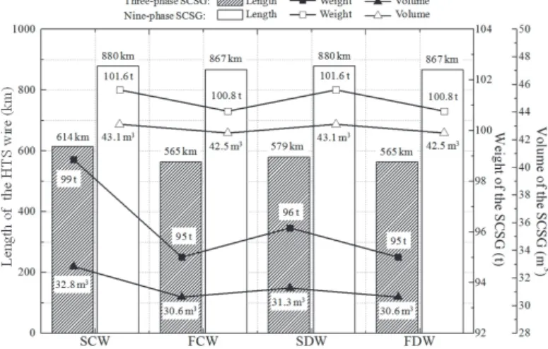
The SCSG must be designed to use the least possible amount of HTS wire because the cost of the wire accounts for a substantial proportion of the manufacturing cost. However, in order to design the overall wind power system, the weight and volume of the SCSG must also be considered. Fig. 9 shows the total length of the HTS wire, volume and weight of SCSGs.
The weight and volume of three-phase SCSGs with FCW and FDW are the lightest and smallest. Moreover, the total length of the HTS wire in three-phase SCSGs with FCW and
Fig. 6. Harmonic spectrum of nine-phase SCSGs.
Fig. 7. Electromagnetic torque waveforms of SCSGs.
Fig. 8. Values of the maximum magnetic field and perpendicular magnetic field of SCSGs.
Fig. 9. Total length of the HTS wire, volume and weight of SCSGs.
FDW is the shortest.
The cost of the full-scale frequency converter of the nine- phase SCSG is lower than the three-phase SCSG. However, considering both the power converter cost and SCSG cost, the wind power system of the three-phase SCSG is cheaper because the total cost of HTS wire in the nine-phase SCSG is higher than the power converter of the three-phase SCSG.
V. CONCLUSION
This paper provides a comparative analysis of 10 MW superconducting wind power generators with three-phase and nine-phase armature windings. The stator windings of SCSGs use four stator winding types.
As a result, the harmonics of SCSGs with SDW and FDW decrease, and the efficiency of the nine-phase SCSG with FDW
is the highest. The torque ripples in the nine-phase SCSGs are lower than three-phase SCSGs. On the other hand, the total length of HTS wire, weight, and volume in three-phase SCSGs with FCW and FDW are the shortest, lightest, and smallest.
All items considered, the design of the three-phase SCSG with FDW is the most appropriate for 10 MW wind power system. The analyzed results will be effectively utilized to design large-scale superconducting generators for wind power generation systems.
ACKNOWLEDGEMENT
This work was supported by the Korea Electric Power Corporation under Grant R18XA03.
REFERENCES
[1] BTM Consult, “International Wind Energy Development: Offshore Report 2013,” BTM, 2012.
[2] B. Maples, M. Hand, W. Musial, “Comparative Assessment of Direct Drive High Temperature Superconducting Generators in Multi-Megawatt Class Wind Turbines,” NREL, 2010.
[3] Hae-Jin Sung, Gyeong-Hun Kim, Kwangmin Kim, Sung-Jun Jung, Minwon Park, In-Keun Yu, Young-Gyun Kim, Haigun Lee, A-Rong Kim, “Practical Design of a 10 MW Superconducting Wind Power Generator Considering Weight Issue,” IEEE Trans. Applied Superconductivity, vol.23, no.3, June. 2013.
[4] Jin Wang, Ronghai Qu, Yingzhen Liu, “Comparison Study of Superconducting Generators With Multiphase Armature Windings for Large-Scale Direct-Drive Wind Turbines,” IEEE Trans. Applied Superconductivity, vol.23, no.3, June. 2013.
[5] H.E. Jordan, R.C. Xowarka. Jr, S.B. Pratap, “Nine-phase Armature Windings Design, Test and Harmonic Analysis,” in Proceedings of IEEE ELT 2004 Conference, May 2005.
[6] Darius Vizireaun, Stephane Brisset, Pascal Brochet, “Design and Optimization of a 9-phase Axial-Flux PM Synchronous Generator with Concentrated Winding for Direct-Drive Wind Turbine,” Proceedings of IEEE IAS 2006 Conference, Florida, USA, October 2006.
[7] Anca D. Hansen, Gabriele Michalke, “Modelling and control of Variable Speed Mult-pole Permanent Magnet Synchronous Generator Wind Turbine,” Wind Energy, vol.11, no.5, pp.537-554, Sep. 2008.
[8] 1547-2003-IEEE Standard for Interconnecting Distributed Resources with Electric Power Systems, IEEE SCC21, 2003, p.13.
Table 4
THD Values of Nine-Phase SCSGs
Stator winding types SCW FCW SDW FDW
THD (%) 9.3 9.6 5.5 6
Table 5
Losses and Efficiencies of SCSGs Three-phase SCSGs
Stator winding types SCW FCW SDW FDW
Stator coil (kW) 154 154 154 154
Magnetic shield (kW) 0.77 0.39 0.53 0.40 Vacuum vessel (kW) 2.88 2.21 1.02 0.92 Windage loss (kW) 0.17 0.17 0.17 0.17 Total loss (kW) 157.8 156.8 155.7 155.5
Efficiency (%) 98.50 98.50 98.52 98.52 Nine-phase SCSGs
Stator winding types SCW FCW SDW FDW
Stator coil (kW) 56.60 56.60 56.60 56.60 Magnetic shield (kW) 0.39 0.29 0.35 0.29
Vacuum vessel (kW) 0.30 0.29 0.27 0.26 Windage loss (kW) 0.20 0.20 0.20 0.20 Total loss (kW) 57.48 57.38 57.42 57.35
Efficiency (%) 99.45 99.45 99.45 99.45