pISSN 1229-3008 eISSN 2287-6251
Progress in Superconductivity and Cryogenics
Vol.19, No.2, (2017), pp.44~47 https://doi.org/10.9714/psac.2017.19.2.044
```
1. INTRODUCTION
With the development of industry, the scaling-up and extension of power grids to satisfy the increased need for power have drawn attention to methods for the efficient operation and safety of electric power systems, and the scaling-up of facilities to protect the power grid from accidents has been necessary [1-3].
A superconducting fault current limiter (SFCL), which is an application based on the quench of superconductors, is drawing attention as an ideal protective device for limiting the fault current of electric power systems. SFCLs have been installed and operated in several test-bed substations in South Korea and other countries [4-5], and SFCLs with various structures have been reported as potential models for improving working characteristics by increasing capacity and limiting the fault current for real power system applications. There have also been SFCL models reported that can control actions for limiting the fault current through two instances of quench depending on the magnitude of the fault current at the initial fault stage [6-10]. However, these transformer-based SFCL models may be affected by iron core saturation depending on the magnitude of the fault current at the initial fault stage due to the SFCL structure, and the fault current limiting action is affected by the winding direction of the two windings and their winding ratio.
This paper proposed a transformer type SFCL model that includes the secondary coupled windings as a transformer type SFCL based on twice quench. The winding direction of the additional secondary winding was
considered as the key design parameter that may affect the current limiting characteristics of the proposed SFCL. To analyze the effect of the winding direction of the additional secondary winding on the current limiting characteristics, the simulated system was constructed and the short-circuit tests were performed. From the analysis on the tests, the quench occurrence for two superconducting elements directly after the fault occurrence was confirmed to be affected by the winding direction of the additional secondary winding comprising the SFCL.
2. STRUCTURE AND OPERATIONAL PRINCIPLE
2.1. Structure and Mechanism
Fig. 1 shows the structure of the transformer type SFCL with the coupled secondary windings, as proposed in this paper. As shown in Fig. 1, the transformer type SFCL was prepared by adding an additional secondary winding (N3) with a superconducting element into the conventional transformer type SFCL with primary winding (N1) and secondary winding (N2). The additional secondary winding may be added either in an additive polarity direction (●) or in a subtractive polarity direction (○), depending on the winding direction.
The working mechanism of the transformer type SFCL with the additional secondary winding is equal to that of the conventional transformer type SFCL. The time interval of quench occurrence between two superconducting elements may be adjusted by the winding direction of the additional secondary winding, expressed as the additive polarity direction or a subtractive polarity direction.
Current limiting characteristics of transformer type SFCL with coupled secondary windings according to its winding direction
Tae Hee Hana, and Sung Hun Limb,*
a Jungwon University , Chungbuk, Korea
b Soongsil Uinversity, Seoul, Korea
(Received 23 March 2017; revised or reviewed 5 June 2017; accepted 6 June 2017)
Abstract
In this paper, the current limiting characteristics of the transformer type superconducting fault current limiter (SFCL) with the two coupled secondary windings due to its winding direction were analyzed. To analyze the dependence of transient fault current limiting characteristics on the winding direction of the additional secondary winding, the fault current limiting tests of the SFCL with an additional secondary winding, wound as subtractive polarity winding and additive polarity winding, were carried out. The time interval of quench occurrence between two superconducting elements comprising the transformer type SFCL with the additional secondary winding was confirmed to be affected by the winding direction of the additional secondary winding. In case of the subtractive polarity winding of the additional secondary winding, the time interval of the quench occurrence in two superconducting elements was shorter than the case of the additive polarity winding.
Keywords: Current limiting characteristics, Transformer type superconducting fault current limiter (SFCL), Coupled secondary windings, Additional secondary winding, Winding direction
* Corresponding author: [email protected]
Tae Hee Han, and Sung Hun Lim
Fig. 1. Structure of the transformer type SFCL with two coupled secondary windings.
Fig. 2. Experimental circuit for short-circuit test of transformer type SFCL with two coupled secondary windings.
2.2. Experimental Apparatus
Fig. 2 is a schematic diagram of the configuration of the experimental circuit to analyze the fault current limiting characteristics of the transformer type SFCL with an additional secondary winding. The circuit was composed of the transformer type SFCL with a circuit including a line impedance (Zline = Rline + jXline = 0.42 + j0.066 [Ω]), a load resistance (Rload = 5 [Ω]), and an AC voltage of (Ein) 120 [V]. The numbers of turn for the windings (N1, N2, N3) were 45, 15, and 45. The two superconducting elements were fabricated into thin film forms with a critical current (IC) of 27 [A]. The current and resistance of the first superconducting element are iSC1 and RSC1, and the current and the resistance of the second superconducting element are iSC2 and RSC2, respectively.
The short-circuit was simulated for four cycles by closing a short-circuit switch (SW2) at a fault angle of 0°
after closing an input power source switch (SW1).
3. RESULT AND ANALYSIS
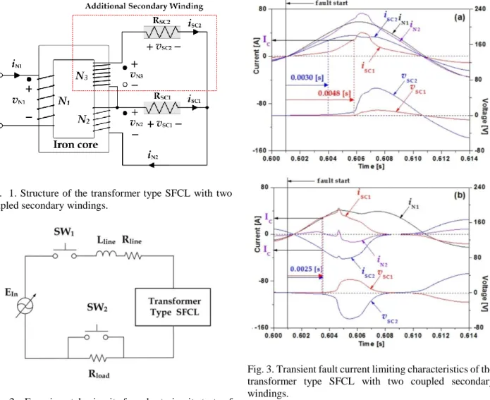
Fig. 3 shows the winding current (iN1, iN2), the currents of superconducting element (iSC1, iSC2), and the voltages of
Fig. 3. Transient fault current limiting characteristics of the transformer type SFCL with two coupled secondary windings.
(a) In case of the additive polarity winding.
(b) In case of the subtractive polarity winding.
superconducting element (vSC1, vSC2) immediately after a fault, depending on the winding direction of the additional secondary winding. In the case of the additive polarity direction as shown in Fig. 3(a), the current flown from the additional secondary winding to the second superconducting element (iSC2) drastically increased earlier than the current flowing into the first superconducting element (iSC1). As a result, a quench firstly occurred at the second superconducting element due to the induction of the voltage (vSC2), and then voltage was induced at the first superconducting element (vSC1). In contrast, in the case of the subtractive polarity direction as shown in Fig. 3(b), the quench occurred simultaneously at both the first and the second superconducting elements directly after fault occurrence.
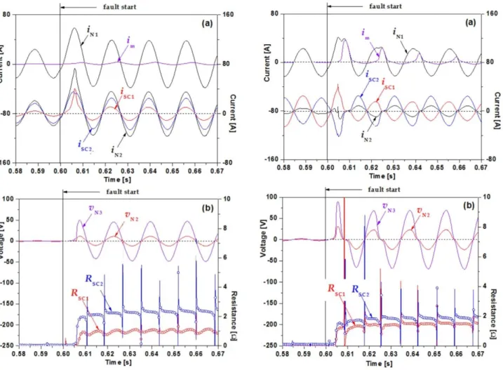
Fig. 4 shows the fault current limiting characteristics in the case of the additive polarity direction of the additional secondary winding. As compared with Fig. 4(b), the voltage of the additional secondary winding (vN3) was about three times higher than the voltage of the existing secondary winding (vN2). In addition, the resistance of the second superconducting element (RSC2) connected with the additional secondary winding was much greater than that of the first superconducting element (RSC1).
45
Current limiting characteristics of transformer type SFCL with coupled secondary windings according to its winding direction
Fig. 4. Fault current limiting characteristics of the transformer type SFCL with two coupled secondary windings in case that its winding direction is the additive polarity winding.
(a) Current waveforms in each winding, two HTSC elements and magnetizing branch.
(b) Voltage waveforms in two secondary windings and resistances of two HTSC elements.
Fig. 5 shows the fault current limiting characteristics in the case of the subtractive polarity direction of the additional secondary winding. The magnetizing current as shown in Fig. 5(a) was higher compared to the case of the additive polarity direction of the additional secondary winding (Fig. 4(a)). The magnetizing current, which initially increased directly after the fault occurrence, gradually decreased as the fault cycles increased. In addition, the distortion in the voltage of the two secondary windings due to the magnetizing current in the early stage of the fault could be observed from Fig. 5(b).
Fig. 5(b) also shows that the difference of the resistance between the two superconducting elements was smaller than the case of the additive polarity direction as shown in Fig. 4(b), which resulted from the simultaneous quench occurrence between two superconducting elements immediately after the fault in the case of the subtractive polarity direction.
Fig. 5. Fault current limiting characteristics of the transformer type SFCL with two coupled secondary windings in the case that its winding direction is the subtractive polarity winding.
(a) Current waveforms in each winding, two HTSC elements and magnetizing branch.
(b) Voltage waveforms in two secondary windings and resistances of two HTSC elements.
4. CONCLUSION
This paper proposed a transformer type SFCL with the additional secondary winding and analyzed its fault current limiting characteristics through the short-circuit tests. The time interval of the quench occurrence in two superconducting elements comprising the SFCL was affected by the winding direction of the additional secondary winding.
The time interval of the quench occurrence in two superconducting elements in case of the subtractive polarity winding of the additional secondary winding was shorter than the case of the additive polarity winding.
Together with the effective design parameters for the variation of the quench occurrence in two superconducting elements in the proposed SFCL, the linkage flux and the magnetizing current, related with the saturation of the iron core, will be performed in the next study.
46
Tae Hee Han, and Sung Hun Lim
ACKNOWLEDGMENT
This work was supported by the Jungwon University Research Grant (2016-062).
REFERENCES
[1] T. Hara, T. Okuma, T. Yamamoto, D. Ito K. Tasaki and K.
Tsurunaga, “Development of a new 6.6kV/1500A class superconducting fault current limiter for electric power system,”
IEEE Trans. Power Delivery, vol. 8, no. 1, pp. 182-192, 1993.
[2] K. -W. Lee, “Power system fault current problems and superconducting fault current limiter,” Superconductivity and Cryogenics, vol. xx, pp. 8-12. 2001.
[3] H. Yamaguchi, T. Kataoka, K. Yaguchi, S. Fujita, K. Yoshikawa and K. Kaiho, “Characteristics analysis of transformer type superconducting fault current limiter,” IEEE. Trans. Appl.
Supercond., vol. 14, no. 2, pp. 815-818, 2004.
[4] Sung-Hun Lim, Tae-Hee Han, Seong-Woo. Yim, Hyo-Sang Choi and Byoung-Sung Han, “Current limiting characteristics of a flux-lock type SFCL dependent on fault angles and core saturation,”
IEEE Trans. Appl. Supercond., vol. 17, no. 2, pp. 1827-1830, 2007.
[5] Sung-Hun Lim, Hyo-Sang Choi, Dong-Chul Chung, Seokcheol Ko and Byoung-Sung Han, “Impedance variation of a flux-lock type SFCL dependent on winding direction between coil 1 and coil 2,”
IEEE Trans. Appl. Supercond., vol. 15, no. 2, pp. 2039-2042, 2005.
[6] H. Hatta, T. Nitta, S. Muroya, T. Oide, Ya Shirai, M. Tawuchi and Y. Miyato, “Study on Recovery Current of Transformer Type Superconducting Fault Current Limiter,” IEEE Trans. Appl.
Supercond., vol. 13, no. 2, pp. 2096-2042, 2005.
[7] Sung-Hun Lim, Young-Sun Cho, Hyo-Sang Choi and Byoung-Sung Han, “Improvement of Current Limiting Capability of HTSC Elements in Hybrid Type SFCL,” IEEE Trans. Appl. Supercond., vol. 17, no. 2, pp. 1807-1810, 2007.
[8] Y. Shirai, S. Noda, K. Yamabe, K. Hattori, J. Baba, T. Nishihara, T.
Nitta, S. Kobauashi and K. Sato, “Surrent Limiting Performance of Three-Phase Concentric Transformer Type SFCL at Unbalanced Fault Conditions,” IEEE Trans. Appl. Supercond., vol. 23, no. 3, pp.
5601905, 2013.
[9] T. Janowski, S. Kozak, B. Kondratowicz-Kucewicz, G.
Wojtasiewicz and J. Kozak, “Analysis of Transformer Type Superconducting Fault Current Limiters,” IEEE Trans. Appl.
Supercond., vol. 17, no. 2, pp. 1788-1790, 2007.
[10] H. Yamaguchi and T. Kataoka, “Current Limiting Characteristics of Transformer Type Superconducting Fault Current Limiter With Shunt Impedance,” IEEE Trans. Appl. Supercond., vol. 17, no. 2, pp.
1919-1922, 2007.
47