GROUND RECEIVING SYSTEM FOR KOMPSAT-2
MOON-GYU KIM, TAEJUNG KIM, SUNG-OG PARK, YONG-JO IM, JI-HYUN SHIN, MYUNG-JIN CHOI, SEUNG-RAN PARK, JONG-JU LEE
Satellite Technology Research Center, KAIST, 373-1 , Yusung-gu, Taejon, 305-701, ROK Tel: (82)-42-869-8626 Fax: (82)-42-861-0064
E-mail: {mgkim, tjkim, sopark, jhshin, prime, yjim, ljj}@satrec.kaist.ac.kr, URL: http://satrec.kaist.ac.kr
ABSTRACT: Remote sensing division of satellite technology research center (SaTReC) , Korea advanced institute of science and technology (KAIST) has developed a ground receiving and processing system for high resolution satellite images. Developed system will be adapted and operated to receive, process and distributes images acquired from of the second Korean Multi-purpose Satellite (KOMPSAT-2), which will be launched in 2004. This project had initiated to develop and Koreanize the state-of-the-art technologies related to the ground receiving system for high resolution remote sensing images, which range from direct ingestion of image data to the distribution of products through precise image correction. During four years development, the system has been verified in various ways including real operation of custom-made systems such as a prototype system for SPOT and a commercialised system for KOMPSAT-1. Currently the system is under customisation for installation at KOMPSAT-2 ground station. In this paper, we present accomplished work and future work.
KEY WORDS: KOMPSAT-2, ground station, satellite, pre-processing, high resolution
1. INTRODUCTION
Since the successful launch of KITSAT series, the Korean Government has implemented a National Space Development Program including the launch of the eight remote sensing satellites namely Korean Multi-purpose Satellite (KOMPSAT) series. The first KOMPSAT with the payload of 6.5m resolution optical sensor, Earth observation camera (EOC), was successfully launched and have been operated archiving thousands of scenes over the world. At present, the second KOMPSAT is under development to be launched in 2004. The payload of KOMPSAT-2 is the Multi-Spectral Camera (MSC), which consists of 1m resolution panchromatic camera and a 4 bands 4m resolution multi-spectral camera.
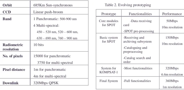
Table 1 shows the specification of KOMPSAT-2.
The ground receiving system for KOMPSAT-2 requires about 40 times enhancement in performance compared to the KOMPSAT-1 ground receiving system.
Data ingestion speed requires about 8 times
enhancement thanks to the on-board compression of
image data. The amount of archiving data to be
managed also increases about 40 times than that of
KOMPSAT-1, hence more superior archive
management scheme is required. These necessities
conclude that the technologies used for middle-
resolution remote sensing data cannot be used for the
ground receiving system for KOMPSAT-2.
To meet the need for new technologies for a ground receiving system for KOMPSAT-2 and the necessity of Koreanization of the ground receiving system to help successful implementation of the National Space Development Program, the remote sensing division of SaTReC has developed ground receiving system for high resolution satellites.
Currently, we have finished system integration and test and the development is at the customisation stage for system installation at the KOMPSAT-2 ground station site.
The paper will provide overview of system development in section 2. In section 3, test result conducted from December 2001 to August 2002 will be given and section 4 will highlight the important features prioritised throughout the development procedures.
Finally, conclusion will be given presenting current stage of development work and future plan.
Table 1. KOMPSAT-2 Specification Orbit 685Km Sun-synchronous
CCD Linear push-broom
Band 1 Panchromatic: 500-900 nm 4 Multi-spectral:
450 – 520 nm, 520 – 600 nm, 630 – 690 nm, 760 – 900 nm Radiometric
resolution
10 bits
No. of pixels 15000 for panchromatic 3750 for multi-spectral Pixel distance 1m for panchromatic
4m for multi-spectral Downlink 320Mbps QPSK
2. OVERVIEW
This section describes the overview of development work of the ground receiving system for KOMPSAT-2 (hereby, the system). The requirements study and the system architecture were described well in
(Hong, 1999) and (Park, 2001).
The main objectives of the system are: 1) real-time receiving and processing of X-band downlink data, 2) generation of standard image products and catalogues, 3) integrated system management, 4) archive management, and 5) comprehensive user interface to provide easy access to satellite image data. To satisfy those objectives, 1 hardware component and 13 software components have been developed. Figure 1 at the end of this paper shows the block diagram of the system developed.
During 4 years development, rapid prototyping has been used for process model to illustrate the progress in functionality and performance of system and verify the system meantime. Table 2 shows functionalities and performance of each prototype developed. The basic system for SPOT was verified with real operation at SaTReC site. The system for KOMPSAT-1 was installed at two sites and is under well operation.
Table 2. Evolving prototyping
Prototype Functionalities Performance Core modules
for SPOT
-Data receiving card
-SPOT pre-processing
50Mbps 10m resolution
Basic system for SPOT
-Receiving and archiving subsystem -Cataloguing and preprocessing -Catalog search and order
150Mbps 10m resolution
System for KOMPSAT-1
-Most functionalities 320Mbps 6.6m resolution Final System -Full functionalities 360Mbps
1m resolution
3. INTEGRATION TEST
The factory acceptance test has been conducted
from December 2001 to August 2002. The test process
consists of component test, integration test and random
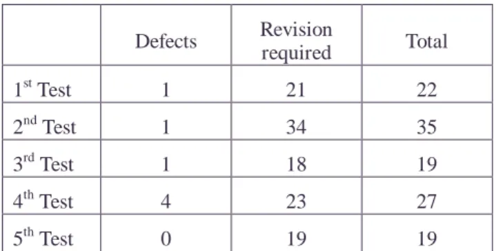
test, and is conducted in this order. Component test and integration test were designed to be able to verify if the system meets all requirements and 110 test procedures were prepared accordingly. Most of test procedures are verification of functionalities of the system and the rest for performance verification. Component test aimed to verify requirements assigned to each component, and integration test was designed to verify mainly interface and integrity of the system. Random test means a validation process not with test procedures but in real operational condition. Considering all misuse of system cannot be designed as test procedures, we let test conductor to use system with minimum training to expose system defects. The purpose of this test is to verify system stability and reliability. If any defects are found during test, regression test from the component test are conducted after defect correction.
Table 3 shows the number of problems reported during 5 cycles of regression tests. 122 problems were reported and all of them resolved.
Performance test were conducted on the real-time data ingestion speed of RAS, accuracy of sensor modeling of CAP, and product generation speed of CAP.
Performance of RAS was tested with payload simulator (PLS) and simulated images provided by KARI. The result showed successful real-time receiving and recording of data at sustained data rate up to 360Mbps with BER of 0. Due to the specification of test equipment, we could not precede test over 360Mbps.
Accuracy of sensor model of CAP was tested with SPOT and EOC of KOMPSAT-1, and it showed less than one pixel RMSE with 11 to 13 GCPs (Choi, 2002).
We are expecting this sensor model can be used for KOMPSAT-2 as well and going to conduct test with KOMPSAT-2 simulated images as they become available. The performance of product generation of CAP was analyzed with KOMPSAT-1 back data, and it is expected to process data received for 3 minutes in about 2 hours with SGI Origin 3200.
Table 3. Functionality test results
Defects Revision
required Total
1
stTest 1 21 22
2
ndTest 1 34 35
3
rdTest 1 18 19
4
thTest 4 23 27
5
thTest 0 19 19
4. IMPORTANT FEATURES OF THE SYSTEM
4.1 Automation, Archive Management and Security of System
During the development of the system, we have emphasized system automation, archive management and security management. First two are very important as the amount of data to be processed and managed are enormous. Security has been emphasised as high- resolution satellite images require higher security. In the developed system, they operate all together systematically.
Workflow of system is managed by a component so called order manager utilizing order and work orders. Order is a user input that requests the system for new image acquisition, product generation from archived raw data, or distribution of archived products.
Once such an order is ingested, order manager produces work order according to required workflow and distributes them to responsible components to fulfil the request of users. The work order is a primitive order to a component such as image acquisition work order to RAS, product generation work order to CAP. Order manager monitors each component’s progress and arrange the sequence of work order. While handling each work order, each component may need user intervention for the approvals, additional information or ingestion of data not available online (archived offline).
To minimize such user interventions, firstly, we
introduced bypassing scheme of operator’s approval
based on the priority of user who makes order. Second category of user intervention includes assigning security level of products, cloud cover assessment and GCP chipping for precision correction. The security level of scenes can be automatically assigned by pre-defined rule sets. Each rule set is defined by area of interests, a period of acquisition and predefined security level.
When new products are generated, predefined security levels are allocated according these rule sets. We also have developed a few automatic processing algorithms such as automatic cloud assessment algorithm and automatic precision correction algorithm. Automatic precision correction can be done utilizing pre-archived GCP chip database (Kim, 2002). Thirdly, we introduced the hierarchical archiving management scheme to minimize for operators to ingest offline data to online.
In this scheme, the near-line data, which is implemented with a DLT tape library physically, are transparent to the system as like they are online. The capacity of a DTL tape library ranges up to 27 terabytes so this scheme minimizes data ingestion from offline to online.
The objective of hierarchical archiving management is to manage storage space and data to minimize operators’ effort to maintain them. For this purpose, the archive management software (AMS) was implemented. AMS divide system’s storage space hierarchically into three: online, near-line and offline.
Online storage is implemented with a RAID and near- line storage with a DLT library. Concept of online storage is to store data most recently acquired and provide them to system quickly as requested. Near-line storage is used for back-up storage and to store data considered to be used in near future. Newly acquired X- band raw data are passed to SPS and stored on the online storage. Products generated from them also stored on the on-line storage. During non-working hour, AMS makes copies of them to near-line storage for the sake of backup. AMS also secure predefined storage space on the online by deleting data files that have already backup on near-line storage. In this manner, the system maintains enough free space for operation on the
online. AMS also manages near-line storage space and data. For required space for near-line, upper and lower limits are needed. Upper limit indicates minimum near- line free space required for system operation and lower limit indicates minimum space can be used for near-line data to provide data service to the system without operators’ intervention. AMS monitors near-line data and space during working hour. If amount of near-line data exceeds the upper limit, AMS secure free space required by dropping the used DLTs automatically in chronological order until the used data space reaches the lower limit. Operators are required to locate new DLTs as AMS requests. For dropped tapes, i.e. offline data, AMS maintains a database of their ID and contents of data on the tape. So if required, AMS requests operator to insert specific DLT to restore off-line data. When certain component requests specific data to AMS, AMS looks for the database and finds the location of data:
online, near-line, or offline. If requested data are on the offline, AMS requests operator to supply offline DLT to near-line. If requested data are on near-line storage, they are automatically restored to online. AMS informs the location of data on the online storage to the component that requested data. In this manner, AMS can service requested data to system with minimum user involvement and other system components uses near- line data transparently.
Purpose of security management is to keep system
integrity from unauthorized accesses and mistaken
operations. In the developed system, the security level is
allocated to users (including operators), data and
functions of each component. These security levels used
for the system to control accessibility. The accessibility
is defined between a user and data, and a user and a
function of each component. Data accessibility is very
clear. User with higher security level can search and
order products with lower security level. Functional
accessibility is a newly introduced scheme. As like data
accessibility, this defines relationship between a user
and a system function. For example, if a certain user has
lower security level than that of an acquisition order
function of CBI, he/she cannot access that function.
Carefully configuration of priority levels can permit only authorized users with enough knowledge and training to have an access to certain functions and data to maintain system integrity.
4.2 High Speed Receiving and Archiving Subsystem
To achieve high performance and easy expandability of receiving and archiving subsystem, both of careful selection of hardware and precise programming are required.
Key hardware components of RAS are data receiving card (DRC), a host computer and RAID. DRC is required to convert serial data input from demodulator to parallel data for recording. DRC was built in-house to have 400Mbps bandwidth. This is the only non-COTS hardware in the whole system. Host computer is needed to receive parallel data from DRC and store them onto RAID. Intel
TMPentium 4 or Xeon server was selected considering their high bandwidth and processing power.
Fast progress of CPU performance and relatively low price compared to high-performance workstation/server also played important roles in the decision process.
While selecting RAID system, the performance and reliability of a dozen of major RAID systems were tested using our own benchmarking program to choose reliable real-time storage equipment. While programming RAS software, careful attention had been paid on optimization. We utilized multi-processors to obtain consistent processing power to maintain sustainable data rate. Also careful buffer management was implemented to handle instant slow-down of writing speed to RAID. Single instruction multiple data (SIMD) instructions of Pentium processors are used for parallel processing to achieve high-speed data handling where applicable. Due to such implementation, the system meets the requirements for MWD performance and post-processing speed. During integration test, RAS showed Real-time receiving and recording of data of sustained data rate up to 360Mbps with BER of 0.
The expandability of RAS was implemented by
modular design. Satellite specific modules can be easily plugged in to the RAS and changing configuration enables acquisition of data of new satellites.
4.3 High Precision Pre-processing Component
The CAP was developed to provide hierarchical processing order for product generation, namely, primary product generation, primary passdata (raw data received from satellite) processing and secondary passdata processing according to their processing priority. In primary product generation, specific scenes explicitly defined by order of user are generated in specified standard product level. This is to provide scenes of region of special interests for such as fire damage assessment and flood assessment promptly.
Secondly, during primary passdata processing, scenes defined in standard processing options in terms of latitude and longitude, and cloud coverage are processed to provide standard products of region of general interests. For example, primary passdata processing can be defined on Korean peninsula with less than 30% of cloud coverage. Lastly, CAP generates rest of scenes for archiving purpose: secondary passdata processing. In such processing order, system can satisfy various requirements in time of product generation.
To achieve high geo-location accuracy, we adopted a sensor model so-called P2A after extensive test (Choi, 2002). Test result showed less than one pixel RMSE with 11 to 13 GCPs.
Another key aspect of CAP is automatic precision correction using automatic GCP matching algorithm. If relevant GCP chips are in the database, CAP finds the positions of GCP chips on the newly acquired image using GCP matching algorithm, and apply random sample consensus (RANSAC) algorithm to exclude outliers, namely false matches, from camera modelling.
5. CONCLUSION AND FUTURE WORK
The development and integration test has been
finished in August 2002. Test results showed
compliance of all requirements as far as the test could be conducted. A few tests that require KOMPSAT-2 specific data, which were not available by that time, had not been conducted. For such tests, we have carried out analysis to verify if the system meets those requirements.
These tests will be conducted with test data as soon as they are provided.
Currently customization is undergoing for the system installation at the KOMPSAT-2 ground station.
System validation according to KOMPSAT-2 development schedule is going to be conducted as well.
Such validation includes the interface test between the system to MSC and mission control element, site acceptance test, and end-to-end test. We will also provide technical supports during LEOP of KOMPSAT- 2 in 2004.
6. ACKNOWLEDGEMENT
The Korean Ministry of Science and Technology (MOST) is acknowledged for supporting this research
through a grant “Development of high-resolution satellite image data receiving and processing system”.
7. REFERENCES
Choi, M. and Kim, T., 2002, Satellite orbit and attitude modelling for geometric correction of linear pushbroom images, Proceeding of ISRS 2002
Hong, M. at al., 1999, Requirements study of a high-resolution satellite image receiving, processing and archiving system, Proceeding of ISRS 1999
Park, S. at al., 2001, Automated image reception, processing and distribution system for KOMPSAT-2, Proceeding of ISRS 2001
Kim, T. and Im, Y., 2002, Automatic Precision Correction of Satellite Images by GCP chip matching and RANSAC, Proceeding of ISRS 2002
Figure 1. Block diagram of the system
yGGhGz G OyhzPG
kGpG t~kG hGG
G kG
GG zG hGz G
jGiGGvGpGzG OjipPG
wGjGiGGvG pGzGOwjipPG
wGzGzG OwzzPG
vGtGzGOvtPG z GG
vGG vGG
tGmGzGOtmPG
hGtG zGOhtzPG z GpGtG
zGOzptzPG
uGtGzG OutPG jGGG
GGGG
mGGG
lGG
|GG jG
vGG yGG
hGG wGG
G kGG vGG G G G
~GGG
GG
jG wG
tG jG lGOtjlPG
jGGG
G
hG
wG
~GGGGG
G jGGwGnG
zGOjhwPG jGG wGG
wG zGGOsGWPG
~GGG
G
zG
G zG
G
vG {G wvkSwhkGyG pGG
tGjGjG pGzGOtpzPG
pGGrvtwzh{TYG tjlG
oGG
GaGvSG uTSGvG kGG
wG
GG
G wGG
G
GOjkSG k}kSGks{G
U P wG
wG G
GG tGGG
G GGG
GMGG
wG