Reduction and decomposition of hazardous SOx by discharge plasma with TiO2
In-Sung Woo * ․Joong-Hee Lee * ․Seong-Kuk Park * ․Myong-Hwan Hwang * ․Byong-Suk Kim **
* Department of Safety Engineering, University of Incheon․ ** Choong Ju national University
이산화티탄 촉매를 이용한 플라즈마 반응에 의한 SOx의 분해
우 인 성 * ․이 중 희 * ․박 성 국 * ․황 명 환 * ․김 병 석 **
* 인천대학교 안전공학과․ ** 충주대학교
Abstract
본 연구에서는 대기오염물질인 유해 황산화물 가스를 이산화티탄 촉매 반응기와 연면 방전 반응기를 조합한 반 응기에서 플라즈마 방전반응에 의하여 주파수 변화, 체류시간, 전극의 굵기, 첨가 모의가스 등의 공정 변수를 변화 시켜 분해제거 실험을 하였다. 실험 결과 황산화물의 분해제거 실험에서 주파수 10kHz에서 소비전력 19W에서 분 해제거율은 99%이었으며 이산화티탄 촉매반응기를 부착한 경우가 없는 경우보다 5%이상 증가효과가 이었다. 첨가 가스로 메탄을 첨가한 경우 분해제거율이 증가하였고, 산소농도가 높아질수록 증가하였다 또한 이산화 탄소를 첨가 한 경우 분해율은 감소하였다.
Keywords : discharge plasma, TiO2 catalyst, SOx decomposition
1. Introduction
While the industrialization of today’s world has benefited human kind a lot to enjoy affluent life, the problems of environmental pollution also have arisen due to release of pollutants in vast amount. Korea also had put its priority on economic growth ahead of others and had little concern to the environmental issues, but now it pays more attention to the envi- ronment to improve the quality of life. The research on environment is also urgent because many devel- oped courtiers are strengthening regulations on environment.
The major pollutants of air include NOx, which is generated from the use of fossil flues such as coal, petroleum and fuel gas, SOx, carbon dioxide, Freon
gas and volatile organic compounds (VOC) such as halogens. Although the methods to deal with such air pollutants are available, their use is limited due to the high cost, difficult energy demand and supply as well as problems of side products. The process by means of plasma is advantageous in terms of en- ergy efficiency and known to have the capacity to remove many kinds of air pollutants simultaneously that exist in a certain system1,2,3).
Therefore, the objective of this experiment is to remove the exhaust gas by letting SOx gas pass through the discharge furnace in the state of non thermal plasma. Further, the experimental results are supposed to be used as fundamental data to optimize SOx decomposition process.
†Acknowledgement: This work is completed by fund of University of Incheon. in 2009.
†교신저자: 우인성, 인천시 연수구 송도동 12-1 인천대학교 안전공학과 M․P: 010-2616-8229, E-mail: [email protected]
2010년 6월 8일 접수; 2010년 8월 17일 수정본 접수; 2010년 8월 20일 게재확정
1
2
3
4
5 6
7 8
10 9
11
12
13
14 15
16 1
2
3
4
5 6
7 8
10 9
11
12
13
14 15
16
1. Sample gas 2. Air bombe 3. O 2 bombe 4. N 2 bombe 5. Mixing tank 6. Flow meter 7. TiO 2 8. Cooling fan 9. SPCP reactor 10. H.V.power supply 11. Gas analyzer 12. Gas chromatograph 13. H.V.probe 14. Oscilloscope 15. By-pass 16. Exhaust
Fig. 1. Schematic diagram of experimental apparatus
2. Experimental Apparatus and Method 2.1 Experimental Apparatus
The schematic diagram of the experimental appa- ratus for decomposition of hazardous gas decom- position by plasma discharge is shown in Figure 14).
The sample gas (SOx) and the background gas are introduced to the mixing tank through the flow meters, and mixed, then injected to the reactor.
Teflon pipe of 10mm diameter which has good corrosion resistance was used for all the gas transportation.
A coil typed Surface discharge induced Plasma Chemical Process (SPCP) was used and a cooling fan was installed to maintain temperature of the re- actor constant.
The electric power for discharge was provided by High Voltage Power Supply. The decomposed gas was analyzed with the combustion gas analyzer shown in Figure 1.
2.2 Experimental Method
We used the standard sample gas of 1,500 ppm SO2 for the experiment. The flow rate of the sample gas which is mixed in the mixing tank is controlled with controlling valves on the flow meter depending on the experimental conditions. The mixed gas is in- jected to the reactor at the flow rates of 100, 200, 500, 800 and 1,000㎖/min, being controlled with the
flow meter and the SOx concentration is measured with the gas analyzer. The gas, which is prepared to have the initial concentrations of 100, 300, 500 and 1,000ppm by mixing nitrogen (99.95% pure) and the standard sample gas, is kept for about 3∼5 min un- til it reaches steady-state and then decomposed.
The experiment was performed at room temper- ature and atmospheric pressure. The Surface dis- charge induced Plasma Chemical Process reactor is sealed with Teflon and the decomposition is initiated after confirming that the initial concentration has reached its steady state with gas analyzer. Observing the wave form with oscilloscope and recorder, the voltage and current of the input power is increased from the minimum power level of clear plasma gen- eration in the reactor. Keeping the input power con- stant, the concentration of SO2 in the gas sample that has passed through the reactor is measured and recorded when it has almost no variation. The ex- perimental variables include the flow rate and con- centration of the standard gas, frequency as well as the materials of the electrode (W, Cu, Al), thickness of the electrode (1, 2, 3 mm), number of coil wind- ing around the electrode (7, 9, 11), background gas (N₂, O₂, air), and additives (CH₄, CO2). The stand- ard setting for these experimental variables was the concentration of the standard gas of 300ppm, the frequency of 10kHz, the flow rate of 200㎖/min, the electrode width of 1mm made of tungsten (W), the number of coil electrode winding of seven, and the background gas of N₂. With fixed variables at this standard setting, only one of the parameters was varied during each experiment5-8). The decom- position efficiency was expressed as the difference of the initial concentration and the concentration after the decomposition divided by the initial concentration.
3. Result and Discussion
Two different modes of experiment were carried out for the SO2 gas decomposition. First, SO2 gas was de- composed without using tin oxide (TiO2) catalysis reactor. Then, the results were compared with the SO2 gas decomposition efficiency of the experiment performed with both TiO2 catalysis reactor and SPCP reactor.
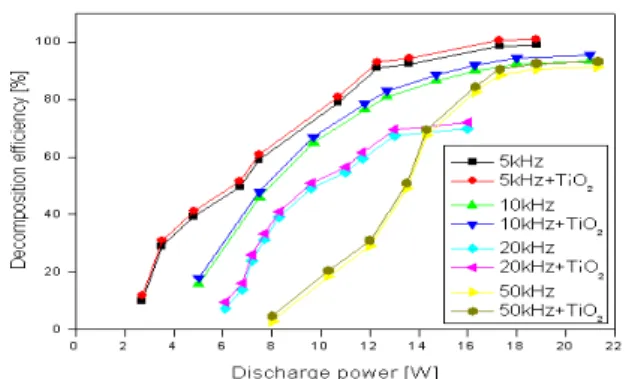
Fig. 2. Effect of electric frequency on decomposition efficiency of SO2 by SPCP reactor with/without TiO2 (CoNO : 300ppm, frequency : 10 kHz, base gas : N2, discharge electrode : W)
Figure 2 shows the hazardous gas decomposition with TiO2 catalysis reactor and SPCP reactor at the conditions of the initial concentration of 300ppm, the flow rate of 200㎖/min with the base gas of nitrogen, in the installed plasma gas decomposition apparatus.
The result shown in Figure 2 is the SO2 gas de- composition efficiency as a function of discharge power at each frequency of 5, 10, 20, and 50 kHz.
The result shows that the decomposition efficiency was highest when the electric frequency was 5 kHz with the power of 20.2W. Addition of TiO2 catalysis increased the decomposition efficiency a little. As the discharge power increased, thedecomposition effi- ciency increased exponentially in the beginning and gradually increased in the rage of high discharge power of 13 ∼ 21W. Decomposition efficiency de- creased when the frequency was decreased above 20 kHz as well as in the low frequency ranges under 5 kHz. This result is in consistency with the results of Jinsong et al.8) about SO2 decomposition under pulse corona discharge at the initial concentration of 1,100ppm. However, our results is in contrast with the result in low frequency range under 5kHz, that is, NO decomposition in between 50 ∼ 800Hz, and NOx decomposition in between 60 ∼ 400 Hz.
In summary, the decomposition efficiency increases as the frequency increases in the low frequency range, and as the frequency decreases in the high- frequency range. The frequency boundary identified from our experimental range was between 5 ∼ 10 kHz. This is because the discharge efficiency is low in the low frequency range of 5 kHz. In the high
frequency range, the discharge efficiency is also re- duced because the conductivity of the non-conductive gas is increased and thus the current flows through the reactor surface as the frequency increases at high voltage. Mizuno5), in the NOx decomposition experiment performed with PPCP reactor, explained that it is because the radicals generated in relatively large amount at high frequency are recombined to each other. The maximum decomposition efficiency appears when the current is maximized by the reso- nance that occurs when the inductive reactance and capacitive reactance are the same to increase the momentum.
Figure 3 is the result of hazardous gas decom- position experiment with TiO2 catalysis reactor and SPCP reactor at the conditions of the initial concen- tration of 300ppm, the electric frequency of 10 kHz and the base gas of nitrogen.
The experimental results show that the decom- position efficiency is the highest when the discharge power is 19.0W. The decomposition efficiency is higher as the residence time of SO2 gas is logger,
Fig. 3. Effect of residence time on decomposition efficiency of SO2 by SPCP reactor with/without TiO2 (CoNO : 300ppm,
frequency : 10 kHz, base gas : N2, discharge electrode : W)
Fig. 4. Effect of electrode material on decomposition efficiency of SO2 by SPCP reactor with/without TiO2 (CoNO : 300ppm, frequency : 10 kHz, base gas : N2, discharge electrode : W)
that is, the flow rate is smaller. When TiO2 catal- ysis reactor is added, the decomposition efficiency increases a little in each experiment. This increase in decomposition efficiency is presumably due to the increased generation of radicals that have higher en- ergy to react with SO2 gas molecules as the colli- sion frequency (Ʋe) increases when the flow rate is low and the residence time is longer.
Figure 4 shows the hazardous gas decomposition with TiO2 catalysis reactor and SPCP reactor at the conditions of the initial concentration of 300ppm, the flow rate of 200㎖/min and the electric frequency of 10 kHz with the base gas of nitrogen, in the installed plasma gas decomposition apparatus. The SO2 gas decomposition efficiency as the function of discharge power is shown in figure 4 for each electrode materi- als of tungsten (W), copper (Cu) and aluminum (Al).
The maximum decomposition efficiency was ob- tained with the electrode material of tungsten. When TiO2 catalysis reactor is added, the decomposition ef- ficiency increases a little in each experiment. This is because the electrode temperature is elevated as the melting point and electric resistance of an electrode material are higher and this leads to enhanced dis- charge of ions, that is, plasma. As the melting point of an electrode material is low, the electrode becomes nearly a liquid state and this leads to increased pollu- tion on the surface of the electrode by chemical re- actions of the decomposed gas and decrease perform- ance of the electrode. For example, the electric re- sistances at the room temperature and 2000K are dif- ferent for aluminum (2.65 and 39x10⁸ Ω․m) and cop- per (1.678 and 33 x10⁸ Ω․m), while those of tung- sten are almost same (5.28 and 58x10⁸ Ω․m).
However, the flash over potentials of copper and aluminum in SPCP reactor are 66.5 and 68 kV, re- spectively, which shows that aluminum requires more energy and thus has lower decomposition efficiency.
We assume that this is because the energy required to make discharge is higher and this assumption is in consistency with the study of Gasparik9). Moreover, for the melting points of the electrode materials of tungsten, copper and aluminum are 3,382℃, 1,084.9℃
and 660.3℃, respectively, tungsten electrode is not molten and the roughness of the electrode surface is maintained to generate more free electrons and thus
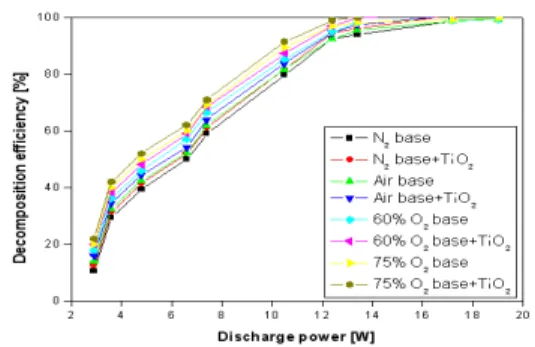
Fig. 5. Effect of base on decomposition efficiency of SO2 by SPCP reactor with/without TiO2 (CoNO : 300ppm, frequency : 10 kHz, base gas : N2, discharge electrode : W)
increase the decomposition efficiency. So, the melting point of the electrode materials and the decomposition efficiency show perfect agreement.
Figure 5 shows the hazardous gas decomposition with TiO2 catalysis reactor and SPCP reactor at the conditions of the initial concentration of 300ppm, the flow rate of 200㎖/min and the electric frequency of 10 kHz in the installed plasma gas decomposition apparatus.
The SO2 gas decomposition efficiency as the function of discharge power with the electrode material of tung- sten is shown in figure 4 for three different base gas- es: nitrogen, air mixture with 60 vol % of oxygen, and air mixture with 75 vol % of oxygen.
The results show that the decomposition efficiency was highest with the base gas of air mixture with 75 vol % of oxygen, and then air mixture with 60 vol % of oxygen and nitrogen gas followed. When TiO2 catalysis reactor is added, the decomposition efficiency increases a little in each experiment. The base gas of air mixture with 75 vol % of oxygen showed better efficiency than that of air mixture with 60 vol % of oxygen. This is presumably be- cause the more oxygen molecules can receive more energy from plasma, participating in radical reaction with SO2 to increase the decomposition efficiency.
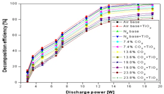
Figure 6 shows the hazardous gas decomposition with TiO2 catalysis reactor and SPCP reactor at the conditions of the initial concentration of 300ppm, the flow rate of 200㎖/min and the electric frequency of 10 kHz with the base gas of nitrogen and air in the installed plasma gas decomposition apparatus. The SO2 gas decomposition efficiency as the function of discharge power with the electrode material of tung
Fig. 6. Effect of simulated gas CO2 on decomposition efficiency of SO2 by SPCP reactor with/without TiO2 (CoNO : 300ppm,
frequency : 10 kHz, base gas : N2, discharge electrode : W)
0 2 4 6 8 10 12 14 16 18 20 22
0 20 40 60 80 100
D ec om po si tio n ef fic ie nc y [% ]
Discharge power [W]
CH
4CH
4+TiO
2CH
40.11%
CH
40.11%+TiO
2CH
40.22%
CH
40.22%+TiO
2CH
40.44%
CH
40.44%+TiO
2Fig. 7. Effect of additive CH4 on decomposition efficiency of SO2 by SPCP reactor with/without TiO2 (CoNO : 300ppm, frequency : 10 kHz, base gas : N2, discharge electrode : W)
sten is shown in figure 4 for different compositions of carbon dioxide: 7.4, 13.6, 19.0, 23.8vol%.
The highest decomposition efficiency was shown in the case when the base gas was air. Higher carbon dioxide content decreased the decomposition efficiency.
When TiO2 catalysis reactor is added, the decom- position efficiency increases a little in each experiment.
Figure 7 shows the hazardous gas decomposition with TiO2 catalysis reactor and SPCP reactor at the conditions of the initial concentration of 300ppm, the flow rate of 200㎖/min and the electric frequency of 10 kHz with the base gas of nitrogen in the installed plasma gas decomposition apparatus. To enhance the decomposition efficiency, methane (CH4) was added with the ration of 0.00, 0.11, 0.22, 0.44 vol % for each experiment and the results, as the function of dis- charge power.
The results show that the decomposition efficiency was highest when the methane content was 0.44 vol
%. The decomposition efficiency increased as the methane content increased and finally reached 100%
Fig. 8. Decomposed mass of SO2 per unit power and second by SPCP reactor with/without TiO2 (CoNO : 300ppm, frequency : 10 kHz, base gas : N2, discharge electrode : W)
with high electric power of 12∼20W. When TiO2 catalysis reactor is added, the decomposition effi- ciency increases a little in each experiment. The in- crease of decomposition efficiency with increasing methane content can be explained that when methane molecules are decomposed into CH3ㆍ and H ㆍ radi- cals, Hㆍ and Oㆍ radicals are also generated and react with each other to produce OHㆍ radicals that are needed to oxidize SO2.
Figure 8 shows the hazardous gas decomposition with TiO2 catalysis reactor and SPCP reactor at the conditions of the initial concentration of 300ppm, the flow rate of 200㎖/min and the electric frequency of 10 kHz with the base gas of nitrogen in the installed plasma gas decomposition apparatus. In order to evaluate electric power efficiency, initial concentration was varied to be 100, 300, 500, 1,000ppm for each experiment to measure the decomposed mass of SO2 per unit time(sec).
The results show that the decomposition efficiency was highest when the initial concentration was 1000ppm. The decomposition efficiency per unit time and unit power increase until it reaches the max- imum and then it is decreased. The maximum de- composed SO2 mass is smaller as the initial concen- tration of SO2 gas is lower. When TiO2 catalysis re- actor is added, the decomposition efficiency increases a little in each experiment. The maximum decom- position efficiency is found at 10.5W for the initial concentration of 1000 ppm, 4.5W for 500ppm and 3.8W for 100∼300ppm. At these points, the electric
0 2 4 6 8 10 12 0
1 2 3 4 5
D e co m p o si tio n e ff ic ie n cy [ % ]
Discharge power [W]
19.0W 19.0W+TiO2 13.6W 13.6W+TiO2 10.5W 10.5W+TiO2 6.5W 6.5W+TiO2 3.0W 3.0W+TiO2
Fig. 9. Power consumption necessary to decompose SO2 by SPCP reactor with/without TiO2 (CoNO : 300ppm, frequency : 10 kHz, base gas : N2, discharge electrode : W)
efficiency is the best. In the range before the max- imum, the electrons with the enough energy to de- compose SO2 are not generated sufficiently, while excessive discharge power is wasted in the range af- ter the maximum.
Figure 9 shows the hazardous gas decomposition with TiO2 catalysis reactor and SPCP reactor at the conditions of the initial concentration of 300ppm, the flow rate of 200㎖/min and the electric frequency of 10 kHz with the base gas of nitrogen in the installed plasma gas decomposition apparatus. The decom- position energy (J) required to decompose 1 mol of NO gas is shown in Figure 9 for each residence time and the slopes of the lines indicate power con- sumption for decomposition of 1 mol of SO2 gas.
The line slopes from the results show that the de- composition efficiency was highest when the power consumption was 3.0W which is the power consumed to decompose 1 mol of SO2 gas. When TiO2 catalysis reactor is added, the decomposition efficiency in- creases a little in each experiment. This is consistent with the trichloroethylene decomposition research by Oda et al.10) which reported that the power consumed to decompose 1 mol of trichloroethylene increases as the residence time and discharge power increase.
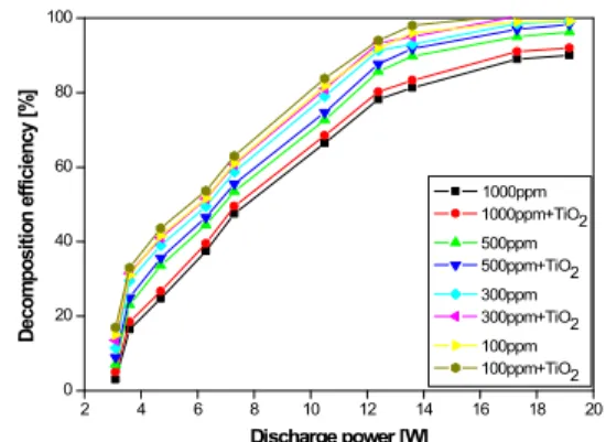
Figure 10 shows the hazardous gas decomposition with TiO2catalysis reactor and SPCP reactor at the conditions of the initial concentration of 300ppm, the flow rate of 200㎖/min and the electric frequency of 10 kHz with the base gas of nitrogen in the installed plasma gas decomposition apparatus. The decom
2 4 6 8 10 12 14 16 18 20
0 20 40 60 80 100
D e c o m p o s it io n e ff ic ie n c y [ % ]
Discharge power [W]
1000ppm 1000ppm+TiO2 500ppm 500ppm+TiO2 300ppm 300ppm+TiO2 100ppm 100ppm+TiO2
Fig. 10. Effect of initial concentration of SO2 decomposition efficiency by SPCP reactor with/without TiO2 (CoNO : 300ppm,
frequency : 10 kHz, base gas : N2, discharge electrode : W)
position efficiency as a function of discharge power is shown in figure 11 for the initial concentration of 100, 300, 500 and 1,000ppm for each experiment.
The results show that the decomposition efficiency was highest when the initial concentration was 100ppm. The decomposition efficiency was higher as the initial concentration was lower, but it increases sharply in the range of 3 ∼ 5W while it increase gradually in the range of high power of 14∼20W.
When TiO2 catalysis reactor is added, the decom- position efficiency increases a little in each experiment.
We assumed that this is because more energy is re- quired to decompose SO2 molecules as the initial concentration is lower. The increase of decomposition efficiency with lower initial concentration can ex- plained that it is because Nㆍ, Oㆍ and OHㆍradicals that are generated by the collision with base gas can have higher probability to react with SO2 molecules or for the free electrons to collide directly with SO2.
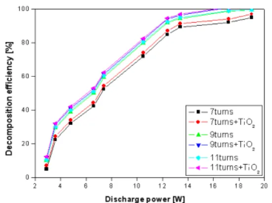
Figure 11 shows the hazardous gas decomposition with TiO2 catalysis reactor and SPCP reactor at the conditions of the initial concentration of 300ppm, the flow rate of 200㎖/min and the electric frequency of 10 kHz with the base gas of nitrogen in the installed plasma gas decomposition apparatus. The decom- position efficiency as a function of discharge power is shown in figure 12 for the number of coil wind ings around the tungsten electrode of 7, 9, and 11 for each experiment.
The results show that the decomposition efficiency
Fig. 11. Effect of number of electrode turn on decomposition efficiency of SO2 by SPCP reactor with/without TiO2 (CoNO:
300ppm, frequency : 10 kHz, base gas : N2, discharge electrode : W)
2 4 6 8 10 12 14 16 18 20
0 20 40 60 80 100
D e c o m p o s it io n e ff ic ie n c y [ % ]
Discharge power [W]
1 mm 1 mm + TiO2 2 mm 2 mm + TiO2 3 mm 3 mm + TiO2
Fig. 12. Effect of thickness of electrode material on decomposition efficiency of SO2 by SPCP reactor with TiO2
catalysis with/without TiO2 (CoNO : 300ppm, frequency : 10 kHz, base gas : N2, discharge electrode : W)
was highest when the number of coil windings around the tungsten electrode was 11. When TiO2 catalysis reactor is added, the decomposition effi- ciency increases a little in each experiment. We as sumed that this is because the discharge area is in- creased as the number of coil windings is increased and the plasma discharge power around the coil is also increased as the width between coils becomes narrower.
Figure 12 shows the hazardous gas decomposition with TiO2 catalysis reactor and SPCP reactor at the conditions of the initial concentration of 300ppm, the flow rate of 200㎖/min and the electric frequency of 10 kHz with the base gas of nitrogen in the installed plasma gas decomposition apparatus. The decom- position efficiency as a function of discharge power is shown in figure 13 for the thickness of the elec- trodes of 1, 2 and 3mm for each experiment. The re-
sults show that the decomposition efficiency was highest the thickness of the electrode was 3mm.
When TiO2 catalysis reactor is added, the decom- position efficiency increases a little in each experiment.
We assumed that the decomposition efficiency in- creases because the discharge area is increased as the thickness of the electrode is greater.
4. Results
In this study, two different types of experiment were performed for the decomposition of the hazard- ous gas. First, the hazardousgas was decomposed without tin oxide catalysis reactor. Then, the ana- lytical results were compared with the gas decom- position efficiencyof the experiment performed with both tin oxide catalysis reactor and SPCP reactor.
The hazardous gas NO was decomposed by the plasma discharge in the specially designed catalysis reactor and SPCP reactor, varying the parameter such as frequency, residence time, concentration, electrode material and additives. The experimental re- sults show that the decomposition efficiency in the tin oxide catalysis reactor is higher by 5∼15% with following conclusions:
1) From the experiments of oxygen concentration of 60% and 75% with the base gas of nitrogen, the decomposition efficiency was higher when there were more oxygen molecules.
2) When the initial concentration was varied into 100, 300, 500 and 1,000ppm, the decomposition effi- ciency was the highest at 1,000ppm.
3) The decomposition efficiencywas the highest when the number of coil windings around the electrode was 11 and the thickness of the electrode was 3mm.
4) The decomposition efficiencywas higher in the case of tin oxide catalysis reactor experiment by 2∼3% compared to the results of the experiment without tin oxide catalysis.
At the electric frequency of 5kHz, the decom- position efficiency was the highest. The maximum decomposition efficiency was found at the power of 20.2W at 5kHz, with some increment by the addition
of tin oxide catalysis.
As the discharge power increased, the decom- position efficiency increased exponentially in the be- ginning and gradually increased in the rage of high discharge power of 13 ∼ 21W. Decomposition effi- ciencydecreased when the frequency was decreased above 20 kHz as well as in the low frequency ranges under 5 kHz.
This result is in consistency with the results of Jinsong et al8) about SO2 decomposition under pulse corona dischargeat the initial concentration of 1,100ppm. However, our result is in contrast with the result in low frequency range under 5kHz, that is, NO decomposition in between 50 ∼ 800Hz, and NOx decomposition in between 60 ∼ 400 Hz.
1) The decompositionefficiencys at the frequency of 10kHz and the power of 19.8, 20.0, 19.0 and 29.6W were 95.4, 85.7, 99.0 and 93.7%, respectively. As the frequency increases in the high voltage range above 20W, the decomposition efficiency was re- duced because the conductivity of base gas was increased and thus the current partly flows through the reactor surface.
2) The maximum decomposition efficiency was ob- tained with the electrodematerial of tungsten fol- lowed by copper and aluminum from the experi- ments in tin oxide catalysis reactor and SPCP reactor. As the thickness of the discharge electrode was larger, the decomposition efficiency was larger.
3) The decomposition efficiency of the hazardous SOx gas when both the tin oxide catalysis re- actor and SPCP reactor were used was 98% un- der the condition of 300ppm concentration, 10kHz frequency and 20W discharge power, which was higher by 5∼15% compared to the results of the experiment when only SPCP reactor was used.
4) The results of added gas experiments, to make similar composition with that of real exhaust gas, show that the decomposition efficiency was in- creased when methane gas (CH4) was added and as oxygen gas concentration increased, but it was decreased as carbon dioxide concentration increased.
5. References
[1] Jung Ho Kim, Byung Chunl Choi, Yong Chunl Kim, "Photocatalytic Technology ", Press University of Junnam, (2009)
[2] Resrarch center of Energy industry,"Statistices of Air pollution material", (2009)
[3] Ogata Azushi etal,"Optimum of decomcomposition of benzene of plasma reaction with TiO2 cata- lyst", J of japan electrostatic, (2004)
[4] Insung Woo, sungkuk park, Myonghwan Hwang,"
decomposition of NOx by discharge plasma with TiO2 catalyst", J of KOSOS, (2008)
[5] In Sung Woo, Hwan myeong Hwang , S. Yamaguma,
"Decomposition of Hazardous gaseous Substances by Discharge Plasma", Korea industrial safety Journal 11(4), (1996):79-83, .
[6] Senichi Masuda, Hidyuki Nakao. "Control of NOx by positive and negative Pulsed Corona Discharges".
IEEE Transaction on Industry Application. VOL.
26, NO. 2, (1990):374-383,
[7] S.Masuda. "Destruction of Gaseous Pollutants and Air Toxics by Surface Discharge Induced Plasma Chemical Process(SPCP) and Pulse Corona Induced Plasma Chemical Process(PPCP)" Non- Thermal Plasma Techniques for Pollution Control.
NATOASI Series G. Ecologic Sciences. Vol. 34.
Part B (1993):1-105.
[8] M. Jinsong, Z. Zhenfeng, Jiyuan, and J. Ruinion,
"Heterogeneous Reaction in the Removal of SO2 from flue gas", Electrostatic Society lecture Result 92. 20 p, Ⅰ 2, (1992):7-11
[9] R. Gasparik. M. Gasparikova, S. Ihara, S. Satoh, and C. Yamabe,"Comparison of Tungsten, Copper, Stainless and Molybdenum Used as HV Electrodes in Wire-to-Plane System Designed for NOx Treatment", Proc. fo NEDO Symp.on Non- Thermal Discharge Plasma Technology for Air Pollution Control, (1997):143-154
[10] A. Ogata, K. Yamanouchi, and K. Mizuno, "Decomposition of Benzene using Alumina-Hybrid Plasma Reactor,"
Proc. of NEDO Sump. on Non-Thermal Discharge Plasma Technology for Air Pollution control, (1997):95-99
저 자 소 개
우 인 성
명지대학교 화공과 공학박사, 현 재 인천대학교 안전공학과 교수, 관심분야는 환경안전, 분진 방화 방폭 등
주소: 인천시 연수구 송도동 12-1 인천대학교 안전공학과
이 중 희
명지대학교 대학원 화학공학과 졸업, 현재 바텍안전 E&C 대표, 관심분야는 화공안전, 가스안전 등이다.
주소: 경기도 부천시 원미구 상동 548-6 강산타운 706
박 성 국
인천대학교 안전공학과(공학박사) 현재 BTM써비스(주) 마케팅 이 사, 관심분야는 화공안전, 건물 방화방폭 안전관리 등이다.
주소: 서울시 영등포구 문래동 3가 55-20 에이스하이테 크시티 1동 821호
황 명 환
일본 일본대학교 전기공학과 공 학박사, 현재 인천대학교 안전공 학과 교수, 관심분야는 전기안전 이다.
주소: 인천시 연수구 송도동 12-1 인천대학교 안전공학과
김 병 석
건국대학교 학사 연세대학교, 동 국대학교 석사 명지대학교 산업 공학과에서 박사를 취득하였으며 현 국립 충주대학교 안전공학과 교수, 대한안전경영과학회 부회 장, 한국안재보상보험학회 부회 장, 대한 안전관리 연구회 회장, 한국산재보험학회 회장.
주소: 서울 송파구 잠실2동 우성아파트 3동 1103호