얇은 연료극 구조가 용융탄산염 연료전지 성능에 미치는 영향
서동호*, 박동녘*, 윤성필*, 한종희*, 오인환*†
*한국과학기술연구원 연료전지연구센터
Influence of the Thin Anode Geometry on the Performance of Molten Carbonate Fuel Cells
DONGHO SEO*, DONGNYEOK PARK*, SUNGPIL YOON*, JONGHEE HAN*, INHWAN OH*† Center for Fuel Cell Reseach, Korea Institute of Science and Technology,
39-1 Hawogokdong, Seongbukgu, Seoul 136-791, Republic of Korea
ABSTRACT
The Ni-Al anodes of the molten carbonate fuel cell (MCFC) with three different structures were successfully fabricated in order to reduce the thickness of the anode down to 0.3 mm; one was the non-supported anode made by a conventional tape casting method, and others were the supported anodes made by lamination or direct casting on the nickel screen. It was seen from the physical analyses and cell operation that the supported thin anodes made by direct casting showed good mechanical strength and cell performance because of a good contact between the anode materials and the support. The single cell using the above anode showed the cell voltage of 0.858 V at the current density of 150mA/cm2 with the nitrogen cross-over of only 0.6% at the operation time of 1,000 h, which was similar to the performance of the conventional thick (0.7 mm) anode. The ability to utilize a thin configuration of anode should cut down the amount of nickel alloy and consequently reduce its manufacturing cost.
KEY WORDS : Molten carbonate fuel cell(용융탄산염 연료전지), Ni-Al anode(니켈-알루미늄 연료극), Supported thin anode(지지체가 있는 얇은 연료극), Direct casting(직접 캐스팅), Cell performance(셀 성능)
†Corresponding author : [email protected]
[ 접수일 : 2011.9.23 수정일 : 2011.10.11 게재확정일 : 2011.10.21 ]
1. Introduction
The fuel cell system is a device that directly converts chemical energy of a fuel into electrical energy by an electrochemical reaction. Fuel cell
technology has advantages of high energy efficiency, low emissions, and multi-fuel feasibilities. In regard to the commercialization of MCFC, it is required a lifetime of 40,000h and a voltage decay rate of less than 10% during this period1,2). Furthermore stack cost down is one of the primary challenges in stack research for many developer besides
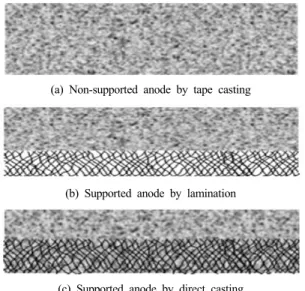
(a) Non-supported anode by tape casting
(b) Supported anode by lamination
(c) Supported anode by direct casting
Fig. 1 Illustration of the different types of thin anode architecture
scale-up and demonstration. There are many approaches to achieve the cost reduction by using alternative low-cost materials, reducing the quantity of material used, and improving manufacturing methods3,4). The conventional MCFC anode is a porous nickel alloyed with aluminum or chromium with thickness of around 0.7 mm. The Ni-Cr or Ni-Al alloy anodes show good performance and acceptable strength against sintering and creepage, but the cost is relatively high and developers are investigating alternative materials5).
As one of the alternative anode material, copper based alloys such as Cu-Al, Cu-Ni-Al, and Cu-Ni-Cr have been evaluated as cheaper anode materials and their electrochemical activities have been found similar to the nickel based anode6). Copper has high electrical conductivity and chem- ical stability in eutectic carbonate, but its sintering and creep resistance have not been satisfactory for MCFC anode. Considerable effort has been devoted to develop sulfur-tolerance anode materials because coal-gasifier derived fuels are heavily laden with sulfur compounds including H2S, COS, CS2, etc. If the anode itself had a high tolerance toward sulfur impurities, the sulfur removal process could be scaled down and consequently to reduce the capital costs of the MCFC plant.
LiFeO2 was suggested as sulfur tolerant materials of MCFC anode7). Yoon and coworkers reported that ceria-coated anode had the ability to suppress the degree of sulfur poisoning due to the ceria reacted with H2S to form Ce2O2S as a sulfur sorbent8).
Some approaches for reduction of manufacturing cost were concentrated on fabrication of thin anodes9). The anode hydrogen oxidation exhibits relatively fast reaction kinetics at the MCFC temperature of 650℃ compared with the cathode oxygen reduction. Partial flooding of anode with
molten carbonate is also acceptable, and this is used to act as a reservoir for carbonate. The major problem of thin anode is mechanical deformation under compressive load in the MCFC operation.
Doyon et al. suggested that the lamination technique could fabricate the thin anode with thickness in the range of 0.13 to 0.64 mm, and the laminated thin anode was found to exhibit the good mech- anical strength10). Porous nickel support can provide the thin anode with mechanical strength and gas diffusion path. However the lamination method is a complex technique requiring many steps including tape casting and pressing under pressure of 10 to 20 MPa with porous support materials.
In this study, three types of anode were pre- pared by different manufacturing methods to reduce the total thickness from conventional 0.7 mm down to around 0.3 mm. The different types of the thin anode architecture were illustrated in Fig. 1. As can be seen in Fig. 1, the anode geometry could be classified according to fabrication process. The non-supported anode is
Fig. 2 The procedure for fabrication of Ni-Al anodes through different methods
typical structure made by tape casting and the supported anode by lamination is double layer structure as mentioned in the previous paragraph.
The supported anode by direct casting process is one body system with Ni-Al anode and nickel screen support. The promising thin structure of MCFC anode was suggested by examination of prepared samples through the test of mechanical strength, cell performance, and post analyses.
2. Experimental
2.1 Fabrication of anodes
Three types of Ni-Al anodes were fabricated by tape casting, lamination and direct casting method as shown in Fig. 2, which consequently led to different morphology of anode electrode.
The solvent (ethanol/toluene), dispersant (BYK110, Altana Chemie), binder (PVB, Butvar), plasticizer (Dibutyl Phthalate, Junsei), and deformer (SN-D348, SanNopco) were mixed through the ball milling for 24 h. The mixture powders of Ni (INCO #255) and Ni-5wt%Al (Twin Energy) alloy with the weight percent of 60/40 were used for the Ni-Al source. The non-supported anode (sample A) was prepared by a conventional tape casting method
having a thickness of 0.31 mm. The laminated anode (sample B) was prepared through two processes including tape casting and lamination.
The lamination procedure was carried out with thin Ni-Al green sheet placed on the nickel screen and applied pressure of 13 MPa at 80℃.
The overall thickness of the sample B involved the support was 0.30 mm. The direct cast anode (sample C) was prepared by pouring the Ni-Al slurry on the nickel screen which was installed on the inclined glass plate. Direct cast anode was made as the one body structure with the overall thickness of 0.32 mm. The nickel screen of sample B and C was the same material purchased from manufacturing company (Fiber Tech.) and thickness was 0.2 mm.
2.2 Characterization of anodes
In order to evaluate a mechanical strength of the different geometry anodes, the bending strength was measured by 3 point bending strength apparatus (LRM-10, NTS technology Co. Ltd.).
The microstructures of anodes were examined with field emission scanning electron microscope (nanoSEM200, NOVA). The pore size distribution was investigated using a mercury porosimetry (Autopore IV, Micromeritics) and the porosity of the samples before and after the cell test was measured using the Archimedes method (ASTM C373-88).
2.3 Single cell test
MCFC performances of the prepared anodes were measured with a single cell configuration having an effective electrode area of 100 cm2. The characteristics of the single cell components and operation condition were summarized in Table 1.
Assembly pressure of 0.196 MPa was applied to
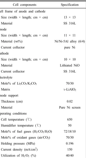
Table 1 Specification of cell components and operation conditions for the MCFC single cell test
Cell components Specification Cell frame of anode and cathode
Size (width × length; cm × cm) 13 × 13
Material SS 316L
Anode
Size (width × length; cm × cm) 11 × 11 Material (wt%) Ni/Ni-5Al alloy (6/4)
Current collector pure Ni
Cathode
Size (width × length; cm × cm) 10 × 10
Material Lithiated NiO
Current collector SS 316L
Electrolyte
Mole% of Li2CO3/K2CO3 70/30
Matrix ɤ-LiAlO2
Anode support
Thickness (cm) 0.02
Material Pure Ni screen
Operating conditions
Cell temperature (℃) 650
Humidifier temperature (℃) 50
Mole% of fuel gases (H2/CO2/H2O) 72/18/10 Mole% of oxidant gases (air/CO2) 70/30
Holding pressure (MPa) 0.196
Current density (mA/cm2) 150 Utilization of H2/O2 (%) 40/40
Fig. 3 Pore size distribution of the prepared samples A, B, and C, sintered at 950℃
the single cell using an air cylinder. Before start-up of the single cell, pre-treatment was carried out for removing the organic binder by thermal decomposition for 4days in air at the temperature ranging from 25 to 450℃ and then for 3 days in CO2 at the temperature ranging from 450 to 650℃. Operation of MCFC single cell was carried out with the constant current of 150 mA/cm2 at the temperature of 650℃. The utilizations of fuel and oxigen gases were both 40% at 150 mA/cm2, respectively. Anode gas mixture was
humidified through a bubbling vessel holding at the temperature of 50℃. Electrochemical impedance spectroscopy (EIS, Solartron 1255B) was conducted to characterize the MCFC performance with the frequency range from 10 kHz to 0.01 Hz during cell operation. The amount of N2 at the anode outlet was monitored by using gas chroma- tography (Agilent Tech. 7890A).
3. Results and discussion
3.1 Characterization of anodes
The prepared anodes by different fabrication method were investigated to determine whether they had the appropriate microstructures for a MCFC anode, after sintered at 950℃. Fig. 3 shows the pore-size distribution of the prepared samples.
The pore-size distribution curves of the prepared samples were in similar shape and the average pore sizes of sample A, B, and C were 3.83, 4.22, and 4.32 μm, respectively. The porosity of the prepared samples A, B, and C was measured by Archimedes method (ASTM C373-88), which
(a) (b)
(c) (d)
(e) (f)
Fig. 4 Surface and cross-sectional SEM images of the prepared anodes sintered at 950℃; (a) and (b) for sample A, (c) and (d) for sample B, and (e) and (f) for sample C
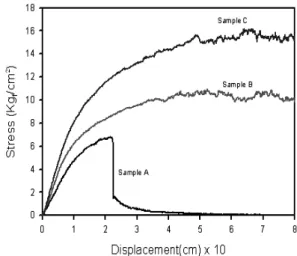
Fig. 5 Bending strength curves of the prepared samples A, B, and C
were 62.5, 66.8, and 62.7%. These results sug- gested that prepared anodes had similar micro- structures and acceptable for a MCFC anode, because the average pore size and porosity of MCFC anode were usually 50∼70% and 3∼6 μm5). The range of the average pore size and the porosity for three different samples falls within the experimental errors, and it seems that the fabrication process do not severely affect the physical properties of the anodes.
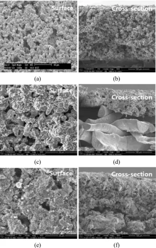
Fig. 4 shows the SEM images of the prepared samples sintered at 950℃. In Fig. 4 (a), (c), and (e) of the surface SEM images, all samples could
be seen to have a similar microstructure and have the sufficient nickel network. In Fig. 4(b), (d), and (f) of the cross-sectional SEM images, however, the prepared samples show the different morphology.
In Fig. 4(b), the non supported anode (sample A) shows the uniform microstructure with a consistent thickness. However, in Fig. 4(d), the lamination anode (sample B) can be discriminated to have an irregular interface and non-tight contact between the thin Ni-Al layer and Ni screen support.
Although the top surface of Ni-Al layer shows the even face in the direction to contact with matrix/electrolyte, the bottom of that shows the non-even face like the embedded structure, which may result in the poor contact between the anode materials and the anode support. In Fig. 4(f), the direct cast anode (sample C) can be seen to have a tight contact between the Ni-Al layer and Ni screen support, because the nickel- aluminum particles are filled into the empty space of Ni screen, which produced the thin anode like one body structure.
Fig. 5 shows the results of the bending strength
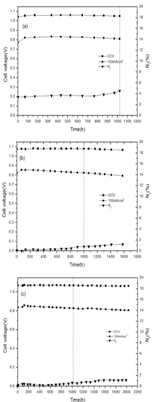
Fig. 6 Single cell performance of MCFC with the prepared anodes along with the operation time; (a) cell A, (b) cell B, and (c) cell C
curves for three samples. The sample A shows the broken point at the displacement of 2.2 mm under stress of 7 kgf/cm2. However, the sample B and C show no broken point within creasing the displacement of samples to 8 mm. The maximum stress of the samples A, B, and C were about 7, 10, and 16 kgf/cm2, respectively. These results indicated that the mechanical strength of the direct cast anode (sample C) seems to be superior to the non-supported anode (sample A) or the laminated anode (sample B), because of the one-body characteristics between the anode materials and the supported screen.
3.2 Performance of the single cell Fig. 6 shows the single cell performances of MCFC assembled with the prepared samples at the operation temperature of 650℃. The cell voltages of each cells at 150 mA/cm2 were in- creased from initial operation time to about 100 h, which should be due to stabilization of cell components including the electrolyte redistribution in matrix and the lithiation reaction in cathode.
The cell performances of each cells decreased gradually after stabilization of cell components.
However, the OCV values of each cells were almost stable over the operation time.
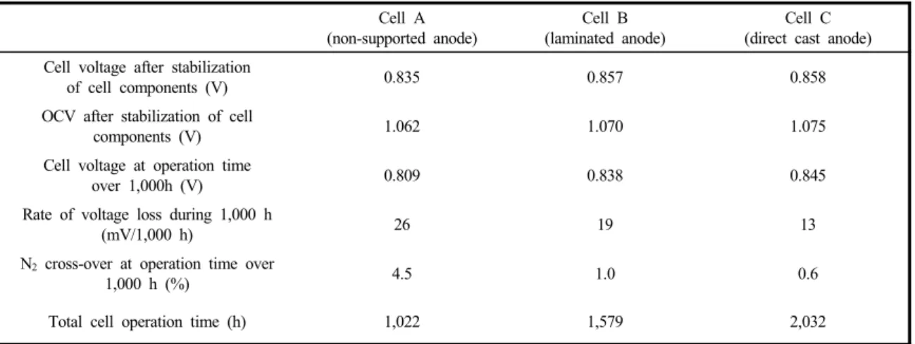
The single cell test of non-supported anode (cell A) was operated up to 1,022 h as shown in Fig. 6(a). The cell voltage and OCV of cell A after stabilization of components were 0.835 V and 1.062 V, and the cell voltage at the operation time around 1,000 h was 0.809 V. The single cell test of laminated anode (cell B) was operated up to 1,579 h as shown in Fig. 6(b). The cell voltage and OCV of cell B after stabilization of com- ponents were 0.857 V and 1.070 V, and the cell voltage at the operation time of around 1,000h
Table 2 The cell performance, OCV, and nitrogen cross-over of each cells over 1000 h
Cell A (non-supported anode)
Cell B (laminated anode)
Cell C (direct cast anode) Cell voltage after stabilization
of cell components (V) 0.835 0.857 0.858
OCV after stabilization of cell
components (V) 1.062 1.070 1.075
Cell voltage at operation time
over 1,000h (V) 0.809 0.838 0.845
Rate of voltage loss during 1,000 h
(mV/1,000 h) 26 19 13
N2 cross-over at operation time over
1,000 h (%) 4.5 1.0 0.6
Total cell operation time (h) 1,022 1,579 2,032
was 0.838 V. The single cell test of direct cast anode (cell C) was operated up to 2,032 h as shown in Fig. 6(c). The cell voltage and OCV of cell C after stabilization of components were 0.838 V and 1.075 V, and the cell voltage at the oper- ation time of around 1,000 h was 0.845 V. All these performances are seen to be not so low compared with those of the single cell with the conventional anode of thickness 0.7 mm11), among which cell C shows the best cell performance.
Comparison of these performances reveals that the rate of cell voltage loss during operation time of 1,000 h of cell A, B, and C were 26, 19, and 13 mV/1,000h, respectively. The cell performance and durability of the direct cast anode showed the better characteristics rather than those of non- supported anode or laminated anode, because the supported anode by direct casting had a thin anode layer with the close contact between anode and support.
The amount of nitrogen cross-over of each cells slowly increased along with the operation time. The increase of nitrogen crossover was caused by the declination of capacity to contain molten carbonate electrolyte in the matrix11).
Furthermore the deformation of thin anode could accelerate the nitrogen cross-over by including the unbalance between cell components. B. Bosio et al. presented that the gas cross-over phenomena was affected by damage to cell components from both experimental and modeling aspects12). The amounts of N2 cross over of cell A, B, and C were 4.5, 1.0, and 0.6% at operation time around 1,000 h, respectively. The nitrogen cross-over of non- supported anode was higher than those of supported anodes, which should be affected by deformation of thin anode. The deformation of the anode structure of cell A will be more described in the following post-analysis section. The cell per- formance, OCV, and nitrogen cross-over of each cells of 1,000 h were summarized in Table 2.
From the results of single cell performance and nitrogen crossover, the preparation of thin anode by direct casting on nickel support could be proposed to improve the durability of cell per- formance as well as the anode material reduction.
By these reason, cell C could be operated up to 2,032 h, longer than the other samples.
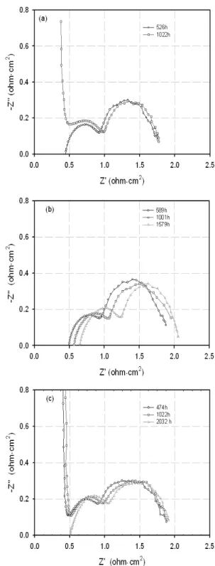
Fig. 7 shows the impedance spectra of each cells measured at OCV during cell operation. In
Fig. 7 Impedance of MCFC single cell with the prepared anodes during operation time; (a) cell A, (b) cell B, and (c) cell C
general, EIS analysis can be used to diagnose the changes in long-term cell performance. Fig. 7(a) shows the impedance spectra of cell A, and the increase of charge transfer resistance was slightly observed as the operation time elapsed. Fig. 7(b) shows the impedance spectra of cell B, and the increase of internal resistance was clearly verified.
The increase of charge transfer resistance of cell B was also noticed between 1,001 h and 1,579 h. Fig. 7(c) shows the impedance spectra of cell C, and the similar impedance curves up to 2,032 h were obtained. But it is rather difficult to compare the effect of the different anode geometry on the EIS, because the hydrogen oxidation reaction and diffusion in anode is very fast13).
3.3 Post analyses of anodes
After single cell operation, post analyses were conducted to estimate the change in morphology of the prepared anodes. The residual carbonate in the anodes was dissolved and removed by boiling water for post analyses. The SEM images of the prepared anodes are shown in Fig. 8. The surface SEM image of sample A shows some cracks as shown in Fig. 8(a), although the cross-sectional images of sample A, Fig. 8(b), shows little images changes. The deformation of the non-supported anode might result from the incapability to stand for compressive load. On the other hands, the surface and cross-sectional SEM images of sample B and C did not show severe cracks as shown in Fig. 8 (c)∼(f). These results conformed that the supported anodes had a good structural resistance for compressive load.
The change in porosity and thickness of the prepared anodes after cell test are summarized in Table 3. The deterioration of the pore structure and thickness of anode contribute to decrease in
(a) (b)
(c) (d)
(e) (f)
Fig. 8 Surface and cross-sectional SEM images of the prepared anodes after cell test; (a) and (b) for sample A, (c) and (d) for sample B, and (e) and (f) for sample C
Table 3 The porosity and thickness of samples before and after cell test
Average pore size(nm)
Porosity(%) Thickness(cm)
Before After Rate of
change Before After Rate of
change(%) Sample A
(Non-supported anode) 4.9 62.5 46.6 25.4 0.31 0.27 12.9
Sample B
(Laminated anode) 4.2 66.8 61.1 8.5 0.30 0.27 10.0
Sample C
(Direct cast anode) 4.3 62.7 58.3 7.0 0.32 0.31 3.1
electrochemical activity and consequently lead to the degradation of the cell performance. The changes of porosity of sample A, B, and C were
25.4%, 8.5%, and 7.0% and the changes of thickness for sample A, B, and C were 12.9, 10.0, and 3.1%.
The change of porosity and thickness for direct cast anode (sample C) was relatively lower than those of non-supported anode or laminated anode, even if the total operation time was quite longer than the others. These results indicated that the thin supported anode made by direct cast has a good structural stability and could improve the durability of a long-term MCFC operation.
4. Conclusions
To reduce the thickness of the Ni-Al anode of the molten carbonate fuel cells from conventional 0.7 mm down to around 0.3 mm, three types anodes with different fabrication methods have been prepared; a non-supported anode by tape casting method (sample A), and a supported one either by lamination method (sample B) or direct casting method (sample C).
Although the different fabrication methods little affected the physical properties of the pore size distribution and porosity, it is seen from the SEM images and the three point bending strength test that sample C showed the best mechanical strength because of the tight contact between the anode materials and the support.
Long term operation of the single cells with the
prepared anodes showed that the cell voltages of cell A, B, and C were 0.835, 0.857, and 0.858 V/cm2, and the voltage loss rates of cell A, B, and C were 25, 19, and 13 mV/1,000h, respectively.
The nitrogen cross-over of cell A, B, and C were also 4.2, 1.0, and 0.6% at the operation time around 1,000h. After the cell test, the change of anode porosity and thickness for cell A, B, and C were seen to be 25.4, 8.5, and 7.0%, and 12.0, 10.0, and 3.1%, respectively.
Based on the results of this work, it is concluded that the thin anode fabricated by direct casting method using the nickel support showed a good cell performance and could be proposed for the reduction of the nickel alloy amount.
Acknowledgements
This study was financial supported by the New
& Renewable Energy of the Korea Institute of Energy Techology Evalution and Planning (KETEP), the Ministry of Knowledge and Economy (MKE) under project contract (2007 NFC 112 P 013050 2009).
References
1) A. Dick, A. Siddle, “Assessment of commercial prospects of molten carbonate fuel cells”, Journal of Power Sources, Vol. 86, 2000, p. 316.
2) H. Morita, M. Kawase, Y. Mugikura, K. Asano,
“Degradation mechanism of molten carbonate fuel cell based on long-term performace: Long- term operation by using bench-scale cell and post-test analysis of the cell”, Journal of Power Sources, Vol. 195, 2010, p. 6988.
3) C. Yuh, R. Jonsen, H. Farooque, H. Maru,
“Status of carbonate fuel cell materials”, Journal of Power Sources, Vol. 56, 1995, p. 1.
4) C. Yuh, J. Colpetzer, K. Dickson, M. Farooque,
G. Xu, “Carbonate Fuel Cell Materials”, Journal of Materials Engineering and Performance, Vol.
15, No. 4, 2006, p. 457.
5) J. Larminie, A. Dicks, “Fuel Cell Systems Explained”, John Wiley & Sons Ltd, 2003, pp.
187-207.
6) E. R. Hwang, J. W. Park, Y. D. Kim, S. G.
Kang, “Effect of alloying elements on the copper-base anode for molten carbonate fuel cells”, Journal of Power Sources, Vol. 69, 1997, p. 55.
7) S. H. Lu, “Investigation of lithium ferrite as an alternate anode material in molten carbonate fuel cells”, Journal of Electrochemcial Society, Vol. 142, No. 11, 1995, p. 3812.
8) H. Devianto, S. P. Yoon, S. W. Nam, J. Han, T.-H. Lim, “The effect of a ceria coating on the H2S tolerance of a molten carbonate fuel cell”, Journal of Power Sources, Vol. 159, 2006, p.
1147.
9) A. Hilmi, C.-Y. Yuh, Mohammad Farooue,
“Anode with ceramic additives for molten carbonate fuel cell”, US patent, 2009, Pub. No.
US20090246562A1.
10) J. D. Doyon, “Fuel cell anode and fuel cell”, US patent, 1996, Patent No. 5,558,948.
11) 김윤영, 한종희, 윤성필, 남석우, 임태훈, “매 트릭스 두께가 MCFC 장기 성능에 미치는 영 형”, 한국수소 및 신에너지학회, Vol. 16, No.
2, 2005, p. 170.
12) B. Bosio, P. Costamagna, F. Parodi, “Modeling and experimentation of molten carbonate fuel cell reactors in a scale-up process”, Chemical Engineering Science, Vol. 54, 1999, p. 2907.
13) J. R. Selman, Y. P. Lin, “Application of ac impedance in fuel cell research and develop- ment”, Electrochimica Acta, Vol. 38 No. 4, 1993, p. 2063.