• 검색 결과가 없습니다.

Fabrication of Core-Shell Structured Ni-Based Alloy Nanopowder by Electrical Wire Explosion Method

N/A
N/A
Protected

Academic year: 2021

Share "Fabrication of Core-Shell Structured Ni-Based Alloy Nanopowder by Electrical Wire Explosion Method"

Copied!
5
0
0

로드 중.... (전체 텍스트 보기)

전체 글

(1)

Fabrication of Core-Shell Structured Ni-Based Alloy Nanopowder by Electrical Wire Explosion Method

A-Young Lee, Gwang-Yeob Lee

a

, Hye-Ryeong Oh, Hyeon-Ah Kim, Song-Yi Kim, and Min-Ha Lee *

Advanced Functional Materials R&D Group, Korea Institute of Industrial Technology, Incheon 21999, Korea

a

Advanced Analysis Center, Korea Institute of Science and Technology, Seoul 02792, Korea (Received November 7, 2016; Revised November 20, 2016; Accepted November 23, 2016)

···

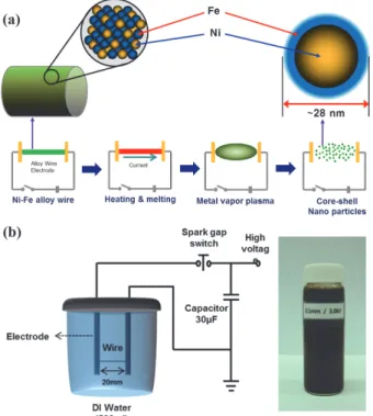
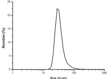
Abstract Electrical wire explosion in liquid media is a promising method for producing metallic nanopowders. It is possible to obtain high-purity metallic nanoparticles and uniform-sized nanopowder with excellent dispersion stability using this electrical wire explosion method. In this study, Ni-Fe alloy nanopowders with core-shell structures are fabri- cated via the electrical explosion of Ni-Fe alloy wires 0.1 mm in diameter and 20 mm in length in de-ionized water. The size and shape of the powders are investigated by field-emission scanning electron microscopy, transmission electron microscopy, and laser particle size analysis. Phase analysis and grain size determination are conducted by X-ray diffrac- tion. The result indicate that a core-shell structured Ni-Fe nanopowder is synthesized with an average particle size of approximately 28 nm, and nanosized Ni core particles are encapsulated by an Fe nanolayer.

Keywords: Electrical wire explosion, Core-shell structure, Nanopowders, Ni-Fe, Grain size

···

1. Introduction

The electrical wire explosion (EWE) method is a prom- ising method for producing metallic nanoparticles. High- purity metallic nanoparticles with a uniform size distribu- tion can be produced by EWE, where the metal or alloy wire is exploded using high pulsed current and voltage during the EWE process [1, 2]. It has been established that the average particle size of nanosized powders syn- thesized in this manner increases with increasing atmo- spheric gas pressure during synthesis, as the increased atmospheric pressure suppresses the expansion of the metallic vapor present during synthesis [3-5].

To produce smaller nanoparticles or those with more narrow size distributions using EWE, the medium around the wire should have high-density inert properties to sup- press the formation of plasma, be able to expand to sup- port the vapor volume present, and have a large heat capacity for rapid cooling of the vapor to prevent parti- cles from being grown through collisions. These condi- tions are critical parameters of the EWE process and

could be satisfied by using a liquid medium [6]. Liquid media have high density around the wire, adequate space is created in the liquid during the explosion by shock pressure, and the vapor and particles can be quickly cooled due to the large heat capacity of the medium [1].

There are several important advantages of liquid EWE processes compared to conventional wire explosions in air. A non-oxide metal powder can be produced without vacuum processing due to the shielding effect of the medium, and the non-oxide phase can be safely kept in the final stage for eventual applied use. Another impor- tant advantage is the homogeneous distribution of the nanoparticles in dispersive liquids such as binder mate- rial for the fabrication of laminate electrodes [5]. Several previous reports have detailed the synthesis of alloy nanoparticles by EWE processing, such Cu-Ni, Cu-Zn and Al-Cu systems [7-9]. However, the detailed forma- tion mechanism of the alloyed nanoparticles, and control over the composition and characteristics of the resulting nanoparticles, are still not well understood due to the complexity of the EWE process [7].

*Corresponding Author: Min-Ha Lee, TEL: +82-32-850-0424,FAX: +82-32-850-0304, E-mail: [email protected]

<PM리뷰>

(2)

Ni-Fe bimetallic powders are widely used for various applications such as in catalysts and soft magnetic materi- als [10, 11]. In addition to the synthesis of nearly spheri- cal FeNi

3

intermetallic compound particles by EWE, Ni-Fe bimetallic alloy nanoparticles have been produced from Ni-plated Fe wires by a pulsed wire discharging method [12, 13]. In this study, we investigate the formation of Ni- Fe bimetallic nanoparticles with core-shell structures cre- ated by EWE of Ni-Fe alloy wires in de-ionized water.

The effects of processing parameters on the particle size, dispersibility and structure are also presented.

2. Experimental

The nickel-iron alloyed nanopowders were fabricated by EWE in liquid media using Ni-42 wt% Fe alloy wires 0.1 mm in diameter. A solid Ni-Fe alloy wire was placed between EWE electrodes with 20 mm interval lengths and a high current density was passed through (~10

10

A/

m

2

) in a very short time period (~10

6

s). Schematic dia- grams of the overall experimental process and the equip- ment setup for EWE are shown in Fig. 1. The Ni-Fe alloy wire, as the electrode material, was placed in a cyl-

inder filled with 500 mL de-ionized water. Typical exper- imental parameters are summarized in Table 1. The size and morphology of the resulting powders were character- ized by field emission scanning electron microscopy (FE- SEM), transmission electron microscopy (TEM) and laser particle size analysis (LPSA). Phase analysis was con- ducted by X-ray diffraction (XRD) with Co-K α radia- tion. The elemental concentration was determined by energy dispersive spectroscopy (EDS).

3. Results and Discussion

XRD analysis of the dried Ni-Fe powders was per- formed in order to investigate the major phase of the syn- thesized nanopowders. XRD patterns obtained from the synthesized Ni-Fe powders are shown in Fig. 2. The sharp peaks diffracted from the crystalline phases of powders correspond to the diffraction data in the JCPDS cards of Fe-Ni (JCPDS 47-1405) and FeO (JCPDS 01- 1223). The extra peak observed in Fig. 2 originates from the oxide layer (FeO) on the particle surface, which forms during drying. The Ni-Fe nanopowder morphol- ogy observed by FE-SEM (Fig. 3) is a typical homoge-

Fig. 1. Schematic diagram of (a) the experimental procedure and (b) EWE equipment, and synthesized Ni-Fe nanopowder dispersed in solution.

Table 1. Experimental parameters of the EWE process.

Wire diameter 0.1 mm

Length of exploded wire 20 mm

Applied voltage 3.0 kV

Capacitance 30 µF

Solution De-ionized water

Fig. 2. XRD pattern obtained from Ni-Fe nanopowder.

(3)

neous distribution of spherical small particles. Moreover, a majority of the particles strongly agglomerated during drying.

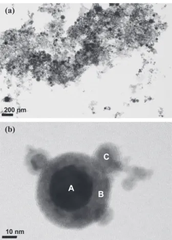
TEM investigations were performed to evaluate the detailed microstructures of the nanopowder, as shown in Fig. 4. Bright field TEM images shown in Fig. 4(a) indi- cate that the particles are nearly spherical in shape, and most particles are less than 30 nm in size. These parti- cles also have a size range over 20 nm and have clear core-shell structures, as shown in Fig. 4(b).

The elemental concentration of the core-shell struc- tured nanopowder was determined by EDS in conjunc- tion with TEM, with the results summarized in Table 2.

The EDS results show that the powder consists of a Ni

r-

ich

Fe solid solution core (region A) and a Fe

rich

Ni solid solution shell (region B). However, the stoichiometry of Ni and Fe in those solid solutions does not match with the stable phases in binary Ni-Fe systems or the initial Ni-Fe alloy wire due to the extreme conditions during EWE processing. For this reason, the XRD diffraction pattern in Fig. 2 only indicates that the powders consist of Ni

50

Fe

50

solid solution (single-phase) due to the reso- lution limits of conventional laboratory X-rays.

Based on the EDS analysis (Table 2), the concentra- tion of Ni in the powder clearly differs between the core and shell regions. The majority of the Ni is concentrated at the core (72.13 wt%; region A) rather than in the shell

(5.76 wt%; region B). However, the concentration devia- tion of Ni is not significant in the smallest particles (39.97 wt% in region C), which arise due to the imma- ture development of core-shell structures by rapid solidi- fication during EWE. Small amounts of oxygen are also present in the shell region. The chemical composition of the particle is different from the initial Ni-Fe alloy wire due to the different vaporization enthalpy values of Ni and Fe, as shown in Table 3, as well as the encapsula- tion of Ni particle by the Fe layer.

The crystalline particle size can be calculated by using Scherrer’s formula [14],

Fig. 3. FE-SEM image showing the surface morphology of the Ni-Fe nanopowder.

Fig. 4. TEM images showing (a) the overall morphology with detail microstructures of Ni-Fe nanopowder, and (b) core-shell nanopowder structures from EDS analysis.

Table 2. Chemical composition of the core-shell structured nanopowder synthesized by EWE.

Region Ni (wt.%) Fe (wt.%)

A 72.13 27.87

B 5.76 94.24

C 39.97 60.03

(4)

D(h k l) = 0.9λ/Bcosθ

B

(1)

where the wavelength of X-rays for Co-K α radiation is λ = 1.7902 Å, and B is the full-width-half-maximum at the peak for 2 θ

B

. The mean crystalline particle size from the XRD diffraction data was estimated to be approximately 20 nm based on equation (1). This estimated value is well- matched with the TEM results shown in Fig. 4.

Fig. 5 shows the particle size distribution of powders obtained from LPSA. The average particle size is approx- imately 28 nm, which is similar to the results obtained by TEM and calculated from Scherrer’s formula. There are no secondary peaks arising from micrometer-sized liquid droplets originated from incomplete vaporization or agglomeration of particles [15], which indicates that the discharge energy of the EWE process is enough to vapor- ize the entire Ni-Fe wire.

Based on the thermodynamic data of Ni and Fe, the formation of these alloy nanoparticles can be considered to involve three stages: over-heating of the wire, the explosion process, and condensation [7]. The wire is rap- idly heated and melts due to a pulsed high-intensity cur- rent. The melted metal is further heated by the ever increasing current density due to increasing resistance, which leads to evaporation of the material and subse- quent plasma formation. The explosion occurs and nano- sized powders are dispersed in the medium at high speeds. The velocity of powder expansion and the sys- tem temperature may exceed 1,000 m/s and 10,000 K, respectively [12].

4. Conclusions

NiFe nanopowder was successfully synthesized by the electrical wire explosion of NiFe alloy wire in de-ion- ized water. The alloyed nanoparticles were nearly spheri- cal in shape with a mean particle size of approximately 28 nm and a narrow size distribution range. TEM results

also indicated that the particles have core-shell structures with partitioning between the constituent Ni and Fe ele- ments. The particle core consisted of a Ni-rich phase while the shell featured an Fe-rich phase based on TEM and EDS result. This study shows that core-shell struc- tured Ni-Fe bimetallic nanopowders can be synthesized from alloy wires via a simple and effective EWE method.

Acknowledgements

This work was supported by the Industrial Strategic Tech- nology Innovation Program (Project No. 20142020103910) funded from the Ministry of Trade, Industry and Energy (MOTIE) through the Korea Institute of Technology Evaluation and Planning (KETEP). Additional support was provided by the Civil-Military Technology Coopera- tion Program under Contract No. 14-BR-MA-05.

References

[1] C. Cho, Y. W. Choi, C. Kang and G. W. Lee: Appl. Phys.

Lett., 91 (2007) 141501.

[2] W. B. Kim, J. S. Park, C. Y. Suh, J. C. Lee, J. H. Kim and Y. J. Oh: J. Korean Powder Metall. Inst., 14 (2007) 108.

[3] W. Jiang and K. Yatsui: IEEE Trans. Plasma Sci., 26 (1998) 1498.

[4] C. Cho, Y. W. Choi and W. Jiang: J. Korean Phys. Soc., 47 (2005) 987.

[5] C. Cho, K. Murai, T. Suzuki, H. Suematsu, W. Jiang and K. Yatsui: IEEE Trans. Plasma Sci., 32 (2004) 2062.

Table 3. Physical properties of elemental starting materials.

Material Vaporization Energy (W

s

, J/mm

3

)

Melting Point (

o

C)

Boiling Point (

o

C)

Ni 53.9 1455 2913

Fe 55.4 1538 2862

Ni-42 Wt%Fe - 1407 -

Fig. 5. Particle size distribution of the Ni-Fe nanopowder

synthesized by EWE.

(5)

[6] C. H. Cho, S. H. Park, Y. W. Choi and B. G. Kim: Surf.

Coat. Technol., 201 (2007) 4847.

[7] Q. Wang, H. Yang, J. Shi and G. Zou: Mater. Sci. Eng. A Struct. Mater., 307 (2001) 190.

[8] W. Kim, J. S. Park, C. Y. Suh, H. Chang and J. C. Lee:

Mater. Lett., 61 (2007) 4259.

[9] Y. S. Kwon, V. V. An, A. P. Ilyinb and D. V. Tikhonov:

Mater. Lett., 61 (2007) 3247.

[10] A. L. Kustov, A. M. Frey, K. E. Larsen, T. Johannessen, J.

K. Nørskov and C. H. Christensen: Appl. Catal. A Gen., 320 (2007) 98.

[11] X. Y. Qin, J. S. Lee, J. G. Nam and B. S. Kim: Nano- struct. Mater., 11 (1999) 383.

[12] L. H. Bac, Y. S. Kwon, J. S. Kim, Y. I. Lee, D. W. Lee and J. C. Kim: Mater. Res. Bull., 45 (2010) 352.

[13] G. H. Park, G. Y. Lee, H. A. Kim, A. Y. Lee, H. R. Oh, S.

Y. Kim, D. H. Kim and M. H. Lee: Mater. Sci. Eng. B Solid State Mater. Adv. Technol., 212 (2016) 24.

[14] Y. R. Uhm, W. W. Kim, S. J. Kim, C. S. Kim and C. K.

Rhee: J. Appl. Phys., 93 (2003) 7196.

[15] C. Cho, Y. Kinemuchi, H. Suematsu, W. Jiang and K.

Yatsui: Jpn. J. Appl. Phys., 42 (2003) 1763.

수치

Table 1. Experimental parameters of the EWE process.
Fig. 3. FE-SEM image showing the surface morphology of the Ni-Fe nanopowder.
Fig. 5 shows the particle size distribution of powders obtained from LPSA. The average particle size is  approx-imately 28 nm, which is similar to the results obtained by TEM and calculated from Scherrer’s formula

참조

관련 문서

Si 마이크로머시닝(mi cromachi ni ng)은 마이크로 열센서(thermalmi crosensor)나 가스 센서의 발달에 영향을 주고 있다 1-3) .현재까지 pol y Si 4) ,Si C 5) ,Ni Fe Al l oy 6) ,Ni

The reason why the Ni-HM secondary battery is not widely used is not necessarily the development technology of the negative electrode material but problem

Immunohi stochemi cal stai ni ng of gastri c adenoma (a) and adenocarci noma(b)formPGES. Immunohi stochemi cal stai ni ng of gastri c adenocarci noma for 15-PGDH.a:negati

The used output data are minimum DNBR values in a reactor core in a lot of operating conditions and the input data are reactor power, core inlet

Third, for the change in balance ability according to core training and plyometric training, the core group showed a significant difference in travel area

Second, a frequency analysis and keyword network centrality of the words in the main texts of the units dealing with “sustainable” core concept was

Figure 6.23 Comparison of the average absorption coefficient between the honeycomb panel and HMPP for a 25-mm core thickness.. 174 Figure 6.24 Comparison of STL between

• Flow in the reservoir and central core of the tube: primary forces are pressure and gravity forces.. • Selective withdrawal: Colder water is withdrawn into the intake channel