Vol. 19, No. 7 pp. 265-274, 2018
This research was supported by the Academic Research fund of Hoseo University in 2017 (2017-0314)
*Corresponding Author : Ki-Jun Kang(Hoseo Univ.) Tel: +82-10-5430-5813 email: [email protected]
Received April 6, 2018 Revised (1st May 11, 2018, 2nd June 12, 2018) Accepted July 6, 2018 Published July 31, 2018
In-Plane Extensional Buckling Analysis of Curved Beams under Uniformly Distributed Radial Loads Using DQM
Ki-Jun Kang
Department of Mechanical Engineering, Hoseo University
등분포하중 하에서 미분구적법(DQM)을 이용한 곡선 보의 내평면 신장 좌굴해석
강기준
호서대학교 공과대학 기계공학부
Abstract The increasing use of curved beams in buildings, vehicles, ships, and aircraft has prompted studies directed toward the development of an accurate method for analyzing the dynamic behavior of such structures. The stability behavior of elastic curved beams has been the subject of a large number of investigations. Solutions of the relevant differential equations have been obtained traditionally using standard finite difference or finite element methods.
These techniques require a great deal of computer time as the number of discrete nodes becomes relatively large under the conditions of complex geometry and loading. One of the efficient procedures for the solution of partial differential equations is the method of differential quadrature. The differential quadrature method (DQM) has been applied to a large number of cases to overcome the difficulties of the complex algorithms of programming for the computer, as well as the excessive use of storage due to the conditions of complex geometry and loading. The in-plane buckling of curved beams considering the extensibility of the arch axis was analyzed under uniformly distributed radial loads using the DQM. The critical loads were calculated for the member with various parameter ratios, boundary conditions, and opening angles. The results were compared with the precise results by other methods for cases, in which they were available. The DQM, using only a limited number of grid points, provided results that agreed very well (less than 0.3%) with the exact ones. New results according to diverse variations were obtained, showing the important roles in the buckling behavior of curved beams, and can be used in comparisons with other numerical solutions or with experimental test data.
요 약 빌딩, 자동차, 선박, 항공기 등에서의 곡선보 사용 증가가 이러한 구조물의 동적거동해석에 필요한 정확한 해법 발전에 괄목할 만한 기여를 해왔다. 탄성곡선 보의 안정성거동은 많은 연구자들의 한 과제분야였다. 전통적으로 미분방정식 의 해법은 유한치분법이나 유한요소법으로 해결해왔다. 이러한 방법들은 복잡한 기하학적 구조 및 하중에 따른 격자점의 증가로 많은 컴퓨팅시간을 요구한다. 편미분방정식의 해를 구하기 위한 효율적인 방법 중의 하나는 미분구적법이다. 복잡한 기하학적 구조 및 하중 은 컴퓨터 용량을 과도하게 사용할 뿐만 아니라, 복합알고리즘 프로그램의 어려움을 극복하기위하여 미분구적법(DQM)이 많은 분야에 적용되어왔다. DQM을 이용하여 곡선 보의 아크 축 신장을 고려한 내 평면 좌굴을 등분포 하중 하에서 해석하였다. 다양한 매개변수 비, 경계조건, 그리고 열림 각에 따른 임계하중을 계산하였다. DQM 결과는 활용 가능한 다른 엄밀해와 비교하였다. DQM은 적은 격자점을 사용하고도 엄밀해 결과와 일치함을 보여주었다 (0.3% 미만).
다양한 변경에 따른 새로운 결과가 또한 제시 되였고, 그 결과는 곡선 보의 좌굴거동에 중요한 역할을 보여주었고, 다른 수치해석결과 혹은 실험결과비교에 사용될 수 있다.
Keywords : Critical Load, DQM, Extensional Buckling, New Result, Radial Load
1. Introduction
Owing to their importance in many fields of technology and engineering, the stability behavior of elastic arches has been the subject of a large number of investigations. Solutions of the relevant differential equations have traditionally been obtained by the standard finite difference or finite element methods.
These techniques require a great deal of computer time as the number of discrete nodes becomes relatively large under conditions of complex geometry and loading. In a large number of cases, the moderately accurate solution which can be calculated rapidly is desired at only a few points in the physical domain.
However, in order to get results with even only limited accuracy at or near a point of interest for a reasonably complicated problem, solutions often have dependence of the accuracy and stability of the mentioned methods on the nature and refinement of the discretization of the domain.
The common engineering theory of flexure is based on the Bernoulli-Euler-Navier assumption that cross sections, which are perpendicular to the centroid before bending, remain plane and perpendicular to the deformed locus.
Ojalvo et al.[1] studied the elastic stability of ring segments with a thrust or a pull directed along the chord. Vlasov[2] derived closed-form solutions such as for an arch, in which cross-sections are allowed to warp non-uniformly along the beam axis, subject to in-plane bending and uniformly distributed radial loads.
Timoshenko and Gere[3] also studied the stability of arches in uniform compression and in uniform bending.
Yang and Kuo[4] studied the static stability of curved thin-walled beams using the principle of virtual displacements in a Lagrangian formulation with emphasis place on the effect of curvature, and they presented closed-form solutions for arches in uniform bending and uniform compression. In addition, different approaches were also presented by Kuo and Yang[5] to support their studies treating a curved beam
as the composition of an infinite number of infinitesimal straight beams. Recently, Kang and Yoo[6] presented a theoretical study on the buckling of thin-walled curved beams with the derivation of stability equations. Han and Kang[7] also investigated the buckling behavior of curved beams neglecting rotatory inertia.
In the present work, the DQM which is a rather efficient alternate procedure for the solution of partial differential equations, introduced by Bellman and Casti[8], is use to analyze the in-plane buckling of curved beams with extensibility of the arch axis under uniform pressure. The critical loads are calculated for the member. The circular beams considered are of uniform cross section, and have both ends either simply supported or clamped. Numerical results are compared with existing exact solutions where available.
2. Differential Equations
The considered uniform circular beam is shown in Fig. 1 under a uniform in ward radial pressure q
xper unit of circumferential length. A point on the centroidal axis is defined by the angle θ, measured from the left support, and the radius of the centroidal axis is R.
The tangential and radial displacements of the arch axis are and u, respectively. v and β are also the displacement at right angles to the plane of the beam and the angular rotation of a cross section, respectively.
These displacements are considered to be positive in
the directions indicated. The compressive force F
zin
the beam is q
xR. This compressive force may causebuckling of the beam either in its plane or out of its
plane.
Fig. 1.Coordinate system with radial loads
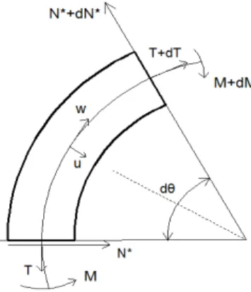
Fig. 2.Forces on a curved beam
The corresponding buckling equations can be deduced from the in-plane vibration equations suggested by Timoshenko and Gere[3] in investigating the torsional buckling of open section columns. His procedure is merely to replace the external load term by a fictitious load whose intensity is the load causing buckling times the appropriate 'curvature' term. The equilibrium conditions of a circular curved beam element neglecting shear deformation, undergoing in-plane vibration as shown in Fig. 2, give
(1)
(2)
(3)
Where
and M are the normal force, internal shear force, and bending moment, respectively. And m is the mass per unit length, and is the time.
From the elementary theory of beams, the normal force and the bending moment are given
(4)
(5)
Here E is the Young's modulus of elasticity, is the cross sectional area, and I is the area moment of inertia of the cross section.
Substituting equations (4) and (5) with equation (3) in equations (1) and (2) leads in the following differential equations of in-plane vibration of curved beams:
″′
′
(6)
″
″′
″
′
(7)
in which each prime denotes one differentiation with respect to the dimensionless distance coordinate
X =θ/θ0
, in which θ
0is the opening angle of the member.
On the basis of Timoshenko and Gere[3], the buckling equations may be deduced from the equation by formally replace the inertial terms suggested by Wah[9]
→
(8)
→
(9)
→
(10)
It may be noted that is the in-plane slope, and is the strain of the center line of a beam during bending.
Substituting equations (8), (9), and (10) into equations (6) and (7) gives
″′
′
″
′
(11)
″
″′
″
′
′ ″
(12)
Using the length of the arch axis
and the radius of gyration of the cross section
, the equations (11) and (12) can be rewritten with the slenderness ratio
″′
′
″
′
(13)
″
″ ′
″
′
′
″ (14)
A mathematical study of the in-plane inextensional condition of small cross section is carried out starting with the basic equations where there is no extension of the center line. This condition requires that w and
u be related by
u =
∂w
∂θ (15)
Using the equation (15) and eliminating in equations (11) and (12), one can write the equation as
wVI
θ60 + 2 wIV θ40 + w''
θ20 =
″
(16)
The equation (16) is the governing equation of in-plane inextensional buckling of the beams.
The boundary conditions for both ends clamped, both ends simply supported, and clamped-simply supported ends are, respectively,
w = u = u' = 0
at X=0 and 1 (17)
w = u = M = 0at X=0 and 1 (18)
w = u = u' = 0at X=0,
w = u = M = 0
at X=1 (19)
3. Differential Quadrature Method
The differential quadrature method (DQM) was
introduced by Bellman and Casti[8]. By formulating
the quadrature rule for a derivative as an analogous
extension of quadrature for integrals in their
introductory paper, they proposed the differential
quadrature method as a new technique for the
numerical solution of initial value problems of ordinary
and partial differential equations. It was applied for the
first time to static analysis of structural components by
Jang et al.[10]. The versatility of the DQM to
engineering analysis in general and to structural
analysis in particular is becoming increasingly evident
by the related publications of recent years. Recently,
Kang and Kim[11], and Kang and Park[12] studied
the vibration and the buckling analysis of asymmetric
curved beams using DQM, respectively. More recently,
Kang and Park[13] analyzed the extensional vibration
of curved beams using DQM. From a mathematical
point of view, the application of the differential
quadrature method to a partial differential equation can
be expressed as follows:
for
(20)
where L denotes a differential operator,
are the discrete points considered in the domain,
are the row vectors of the
values,
are the function values at these points,
are the weighting coefficients attached to these function values, and N denotes the number of discrete points in the domain. This equation, thus, can be expressed as the derivatives of a function at a discrete point in terms of the function values at all discrete points in the variable domain.
The general form of the function
is taken as
for
(21)
If the differential operator L represents an n
thderivative, then
∑
Nj = 1Wijxk - 1j = (k - 1)( k - 2)⋯ ( k - n)xk - n - 1i
for i, k = 1,2,...,N (22)
This expression represents N sets of N linear algebraic equations, giving a unique solution for the weighting coefficients, W
ij, since the coefficient matrix is a Vandermonde matrix which always has an inverse.
4. Numerical Application
The DQM is applied to the determination of the in-plane extensional buckling of the curved beams. The differential quadrature approximations of governing equations and boundary conditions are shown.
Applying the differential quadrature method to equations (13) and (14), gives
(23)
(24)
where A
ij, B
ij, C
ij, and D
ijare the weighting coefficients for the first-, second-, third-, and fourth-order derivatives, respectively, along the dimensionless axis.
The boundary conditions for clamped ends, given by equation (17), can be expressed in differential quadrature form as follows:
w1= 0
at
X = 0 wN= 0at
X = 1 u1= 0at
X = 0 uN= 0at
X = 1∑
N
j = 1A2juj= 0
at
X = 0 +δ∑
N
j = 1A ( N - 1 )juj= 0
at
X = 1 -δ(25) Here, δ denotes a very small distance measured along the dimensionless axis from the boundary ends.
In their work on the application of DQM to the static analysis of beams and plates, Jang et al.[10] proposed the so-called δ-technique wherein adjacent to the boundary points of the differential quadrature chosen grid points at a small distance. This δ approach is used to apply more than one boundary condition at a given station.
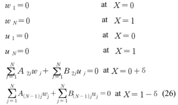
The boundary condition for simply supported ends
given by equation (18) can be expressed in differential
quadrature forms as follows:
w1= 0
at
X = 0 wN= 0at
X = 1 u1= 0at
X = 0 uN= 0at
X = 1∑
N
j = 1A2jwj+
∑
N
j = 1B2juj= 0
at
X = 0 +δ
at
X = 1 -δ(26)
Similarly, the boundary condition for one clamped and one simply supported ends, given by equation (19), can be expressed in differential quadrature forms as
w1= 0
at
X = 0 wN= 0at
X = 1 u1= 0at
X = 0 uN= 0at
X = 1∑
Nj = 1A2juj= 0
at
X = 0 +δ
at
X = 1 -δ(27)
This set of equations together with the appropriate boundary conditions can be solved for the in-plane extensional buckling of the beams.
5. Numerical Results and Comparisons
In-plane extensional buckling parameter
subjected to uniformly distributed radial loads is calculated by the DQM, and the inextensional buckling parameter is also presented together with existing exact solutions by Timoshenko and Gere[3]. The value
q*is evaluated for the case of various end conditions, opening angle
, and slenderness ratio
.
Table 1 presents the results of convergence studies relative to the number of grid point N and a very small distance for the case of both ends clamped with
neglecting extensibility of a curved
beam arch. The data show that the accuracy of the numerical solution increases with increasing N. Then numerical instabilities arise if N becomes too small (possibly smaller than approx. 9) or too large (possibly greater than approx. 14). Table 1 also shows the sensitivity of the solution to the choice of δ. The solution accuracy also decreases due to numerical instabilities if δ becomes too big (possibly greater than approx. ×
). The optimal value for is found 11 ~ 13, and δ is found to be ×
~
×
, which is obtained from trial-and-error calculations. Here, 11 for and ×
for δ are used for all calculations because the exact value of buckling parameter for this case is 8.0 given by Timoshenko and Gere[3] (see Table 5).
In Tables 2~4, the critical buckling parameter
determined by the DQM for the case of both ends clamped, simply supported, and clamped-simply supported ends is presented including the effect of extensibility of the arch axis. The value of the slenderness ratio is 30, 100, and 300, respectively. The first four critical loads of extensional and inextensional buckling parameters for the case of both ends clamped with the slenderness ratio = 300,
, and
are shown in Table 5.
The results by the DQM in Tables 2~5 are presented without comparisons since no data are available. Tables 6~8 also show the critical buckling parameters for the case of both ends clamped, simply supported, and clamped-simply supported ends neglecting the effect of extensibility. The results by the DQM are compared with the exact solutions by Timoshenko and Gere[3]
in Tables 6 and 7.
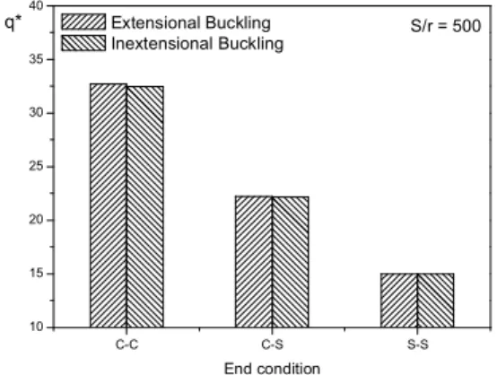
In Figs. 3~6, the buckling parameters of the beam
neglecting or including the effect of extensibility with
both ends clamped (C-C), clamped-simply supported
(C-S), and simply supported (S-S) are compared with
each other. The value of the slenderness ratio is
50 and 500, and the opening angle
is 90 and 180
degree, respectively.
From Tables 2~8, it is seen that the critical buckling parameters of the member with clamped ends are much higher than those of the member with simply supported ends. The buckling parameter can be increased by decreasing the opening angle θ
0and the slenderness ratio . However, When the value of the slenderness ratio is greater than 300, the difference between extensional and inextensional buckling values is less than 2.0 percent. The variation of the slenderness ratio
affects the buckling behavior of both ends clamped boundary condition more significantly than of both ends simply supported boundary condition. The values of buckling parameters using extensional theory are slightly larger than those using inextensional theory. However, the values with rotatory inertia term
in equations (11) and (12) are almost the same as those without rotatory inertia term shown in equation (16) if the value of
is greater than 1000. The beam behavior is affected more importantly by clamped-clamped end conditions, smaller opening angles, and smaller slenderness ratio due to the effects of shear deformation. The shear deformable theory which takes into account the rotary inertia and shear effects gives a better approximation to the actual beam behavior for a thick beam. Therefore, the shear deformable beam theory should be considered the next research.
Han and Kang[7] calculated the critical buckling parameters using inextensional theory given in equation (16), and the results are in Tables 6~8. In Tables 6 and 7, the critical load
is compared with the exact solutions by Timoshenko and Gere[3] for the case of both ends clamped and simply supported. The DQM also shows the excellent agreements with the exact solutions by Timoshenko and Gere[3].
From Figs. 3~6, the buckling parameters of the member including extensibility are more affected by clamped-clamped end conditions than by any other boundary conditions. The difference between extensional and inextensional buckling values becomes larger as the slenderness ratio becomes smaller.
As it can be seen, the critical values of buckling parameters of the beam including extensibility affect the beam behavior more importantly. Therefore, the buckling analysis of curved beams with extensional theory is necessary for the beam behavior.
Table 1. Critical load of in-plane inextensional buckling parameter with both ends clamped for a range of grid points N and a very small distance ;
×
9 11.81 11.96 11.84 9.895 8.948
10 10.93 10.67 7.840 8.221 8.064
11 9.831 8.204 8.076 7.990 8.008
12 10.72 10.09 8.002 8.007 8.003
13 8.002 8.683 7.993 7.984 8.085
14 16.31 8.018 7.792 7.857 11.67
Table 2. Critical load of in-plane extensional buckling parameter with both ends clamped; =11 and ×
(degree)
30 100 300
30 295.9 295.8 295.7
60 73.83 73.76 73.76
90 32.71 32.63 32.59
120 18.34 18.27 18.25
150 11.72 11.64 11.63
180 8.158 8.087 8.072
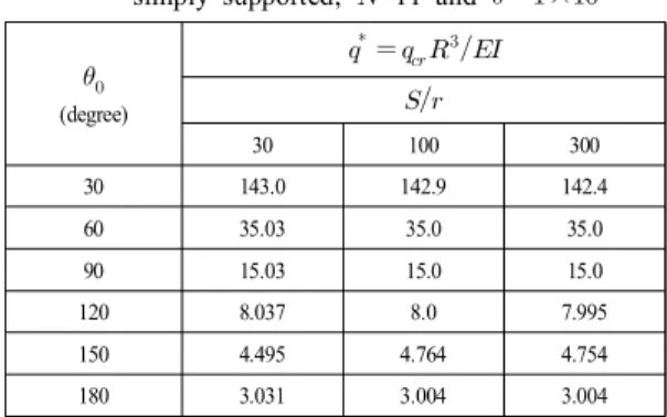
Table 3. Critical load of in-plane extensional buckling parameter with both ends simply supported; =11 and ×
(degree)
30 100 300
30 143.0 142.9 142.4
60 35.03 35.0 35.0
90 15.03 15.0 15.0
120 8.037 8.0 7.995
150 4.495 4.764 4.754
180 3.031 3.004 3.004
Table 4. Critical load of in-plane extensional buckling parameter withboth ends clamped-simply supported; =11 and
×
(degree)
30 100 300
30 226.5 203.3 205.7
60 47.81 50.90 51.10
90 22.01 22.28 22.27
120 12.25 12.24 12.23
150 7.673 7.614 7.624
180 5.184 5.113 5.120
Table 5. The first four critical loads of in-plane extensional and inextensional buckling parameters, , with both ends clamped; =11,
×
, and =300
(degree) ( and )
Extensibility Inextensibility
n=1 32.59 8.072 32.46 8.008
n=2 53.39 12.91 52.38 12.68
n=3 82.91 20.18 86.86 21.50
n=4 309.2 82.38 305.9 79.05
Table 6. Critical load of in-plane inextensional buckling parameter with both ends clamped; =11 and ×
(degree)
Timoshenko and Gere[3] DQM
30 294 294.4
60 73.3 73.39
90 32.4 32.46
120 18.1 18.15
150 11.5 11.55
180 8.0 8.008
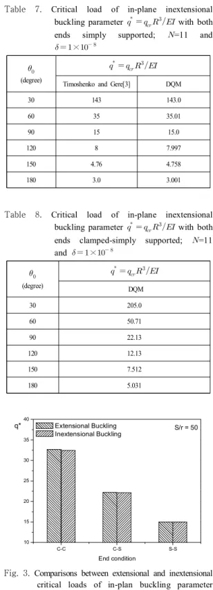
Table 7. Critical load of in-plane inextensional buckling parameter with both ends simply supported; =11 and
×
(degree)
Timoshenko and Gere[3] DQM
30 143 143.0
60 35 35.01
90 15 15.0
120 8 7.997
150 4.76 4.758
180 3.0 3.001
Table 8. Critical load of in-plane inextensional buckling parameter with both ends clamped-simply supported; =11 and ×
(degree)
DQM
30 205.0
60 50.71
90 22.13
120 12.13
150 7.512
180 5.031
C-C C-S S-S
10 15 20 25 30 35 40
S/r = 50 q*
End condition Extensional Buckling Inextensional Buckling
Fig. 3. Comparisons between extensional and inextensional critical loads of in-plan buckling parameter
; =11, × , =50, and
=
C-C C-S S-S 10
15 20 25 30 35 40
S/r = 500 q*
End condition Extensional Buckling Inextensional Buckling
Fig. 4. Comparisons between extensional and inextensional critical loads of in-plan buckling parameter
; =11, × , =500, and =
C-C C-S S-S
2 3 4 5 6 7 8 9 10
S/r = 50 q*
End condition Extensional Buckling Inextensional Buckling
Fig. 5. Comparisons between extensional and inextensional critical loads of in-plan buckling parameter
; =11, × , =50, and
=
C-C C-S S-S
2 3 4 5 6 7 8 9 10
S/r = 500 q*
End condition Extensional Buckling Inextensional Buckling
Fig. 6. Comparisons between extensional and inextensional critical loads of in-plan buckling parameter
; =11, × , =500, and =
6. Conclusions
The DQM was applied to the computation of the eigenvalues of the equations governing the in-plane buckling of curved beams under the uniformly distributed radial loads including extensibility of a beam arch. The present approach gives excellent results for the cases treated while requiring only a limited number of grid points: only eleven discrete points were used for the evaluation. New results are given for three sets of boundary conditions not considered by previous investigators for the in-plane extensional buckling analysis: clamped-clamped ends, simply-simply supported ends, and clamped-simply supported ends.
The present approach gives the followings:
1) The results by the DQM give the mathematical precision compared with the exact solutions by others for the cases in which they are available.
2) Only eleven discrete points are used for the evaluation.
3) It requires less than 1.0 second to compile the program with IMSL subroutine using a personal computer.
4) Diversity of new results according to the opening angles, boundary conditions, and slenderness ratio is also suggested. Those results can be used in the comparisons with other numerical solutions or with other experimental test data.
References
[1] M. Ojalvo, E. Demuts, F. Tokarz, "Out-of-plane buckling of curved members", J. Struct. Dvi., ASCE, Vol. 95, pp. 2305-2316, 1969.
[2] V. Z. Vlasov, Thin walled elastic beams, 2nd edn, English Translation, National Science Foundation, Washington, D.C., 1961.
[3] S. P. Timoshenko, J. M. Gere, Theory of elastic stability, 2nd edn, McGraw-Hill, New York, 1961.
[4] Y. B. Yang, S. R. Kuo, "Static stability of curved thin-walled beams", J. Struct. Engng, ASCE, Vol. 112, pp. 821-841, 1986.
[5] S. R. Kuo, Y. B. Yang, "New theory on buckling of curved beams", J. Engng Mech., ASCE, Vol. 117, pp.
1698-1717, 1991.
[6] Y. J. Kang, C. H. Yoo, "Thin-walled curved beams II:
Analytical solutions for buckling of arches", J. Struct.
Engng, ASCE, Vol. 120, pp. 2102-2125, 1994.
[7] J. Han, K. Kang, "Buckling analysis of arches using DQM", J. KIIS., Vol. 12, pp. 220-229, 1997.
[8] R. E. Bellman, J. Casti, "Differential quadrature and long-term integration", J. Math. Anal. Applic., Vol. 34, pp. 235-238, 1971.
[9] T. Wah, "Buckling of Thin Circular Rings under Uniform Pressure", Int. J. Solids Struct., Vol. 3, pp. 967-974, 1967.
[10] S. K. Jang, C. W. Bert, A. G. Striz, "Application of differential quadrature to static analysis of structural components", Int. J. Numer. Mech. Engng, Vol. 28, pp.
561-577, 1989.
[11] K. Kang, Y. Kim, "In-plane vibration analysis of asymmetric curved beams using DQM", JKAIS., Vol.
11, pp. 2734-274, 2010.
[12] K. Kang, C. Park, "In-plane buckling analysis of asymmetric curved beams using DQM", JKAIS., Vol.
141, pp. 4706-4712, 2013.
[13] K. Kang, C. Park, "Extensional vibration analysis of curved beams including rotatory inertia and shear deformation using DQM", JKAIS., Vol. 17, pp. 284-293, 2016.
Ki-Jun Kang
[Regular Member]•Feb. 1984 : Chungnam National University, Dept. of Mechanical Engineering (B.S),
•Dec. 1989 : San Jose State University, Dept. of Mechanical Engineering (M.S)
•Dec. 1995 : University of Oklahoma, Dept. of Mechanical Engineering (Ph.D)
•Mar. 1997~ the present : Dept. of Mechanical Engineering, Hoseo University, Professor
<Areas studied>
Structural and Numerical Analysis, Buckling, Vibration