Accuracy Comparison of Direct Georeferencing and Indirect Georeferencing in the Mobile Mapping System
Sang-Keun Bae Master Course
Department of Geoinformatic Engineering, Inha University 253 Yonghyun-dong, Nam-gu, Incheon 402-751, Korea
Tel.: +82-32-865-5110, Fax: +82-32-863-1506, E-mail : [email protected]
Byung-Guk Kim Professor
Department of Geoinformatic Engineering, Inha University 253 Yonghyun-dong, Nam-gu, Incheon 402-751, Korea
Tel.: +82-32-860-7603, Fax: +82-32-863-1506, E-mail : [email protected]
Jung-Gon Sung Research Fellow
Highway Research Department, Korea Institute of Construction Technology 2311 Daehwa-dong, Ilsan-gu, Goyang-si, Gyeonggi-do 411-712, Korea Tel.: +82-31-910-0179, Fax: +82-31-910-0746, E-mail : [email protected]
Abstract : The Mobile Mapping System is an effective method to acquire the position and image data using vehicle equipped with the GPS (Global Positioning System), IMU (Inertial Measurement Unit), and CCD camera. It is used in various fields of road facility management, map update, and etc. In the general photogrammetry such as aerial photogrammetry, GCP (Ground Control Point)s are needed to compute the image exterior orientation elements (the position and attitude of camera). These points are measured by field survey at the time of data acquisition. But it costs much time and money.
Moreover, it is not possible to make sufficient GCP as much as we want. However Mobile Mapping System is more efficient both in time and money because it can obtain the position and attitude of camera at the time of photographing. That is, Indirect Georeferencing must use GCP to compute the image exterior orientation elements, but on the other hand Direct Georeferencing can directly compute the image exterior orientation elements by GPS/INS. In this paper, we analyze
about the positional accuracy comparison of ground point using the Direct Georeferencing and Indirect Georeferencing.
Keywords: Mobile Mapping System, Direct Georeferencing
1. Introduction
For efficient management of the road and traffic control, the construction of the Road Facility Database is very important and necessary. One of the ways to acquire the data for the database is to take images along the target road, and extract necessary features and objects.
Obviously, if this data acquisition and processing is fully automatic, the construction, management and update of the database could be easy and efficient.
The Mobile Mapping System(MMS) is integrated by the Global Positioning System(GPS), Inertial Navigation System(INS) and CCD camera for the automatic data acquisition and processing. The exterior orientations of
Fig. 2. DMU-FOG the CCD camera are provided by GPS and INS so that
the obtained images can be processed in near-real time.
Therefore, the accuracy of the product from the MMS highly depends on the accuracy of positions and attitudes from the GPS/INS integration system. But in the traditional photogrammetry such as aerial photogrammetry, the exterior orientations of the CCD camera can be only computed using the Ground Control Points (GCP). This is also called Indirect Georeferencing.
It costs much time and money to measure the GCP.
Moreover, if we take images along the road to make a map, it is not possible to install the sufficient GCP as much as we want.
In this paper, the positional accuracy comparison of objects on the road using the Direct Georeferencing and Indirect Georeferencing is presented. The exterior orientations of the CCD camera were calculated both digital photogrammetry system and GPS/INS loaded on the MMS to measure the position of the targets. And then these results were compared with the value measured by GPS survey.
2. The equipment
1) GPS
The GPS was used NovAtel DL-4 in this study. This is used L1/L2 to acquire the precise position data and 1pps signal can be gotten from the receiver. Also pps signal can be controlled 0.1 ~ 10 sec interval.
2) IMU
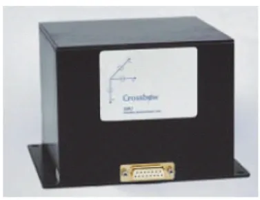
The IMU used in this study is VG600CA-200, the
Dynamic Measurement Unit-Fiber Optic Gyro(DMU- FOG), manufactured by Crossbow (Fig. ()). It has 3-axis accelerometers and gyros measuring the accelerations and rotations with respect to an inertial frame. It should be noted that the biases and scale factor errors of accelerometers and gyros are hundreds to thousand times poorer than high-performance IMU such as LN 100 from Litton.
3) CCD Camera
The CCD Camera was used SVS085 color CCD. This is a progressive sensor with 1280×1024 pixels and pixel size is 6.7
×6.7μm. The progressive-Sacn-Technology provides an image with full resolution even in asynchronous or flash mode. The camera’s output is a 10-bit signal and it has 12 or 25 full frames/sec.
3. Direct Georeferencing
3. Direct Georeferencing
For some mapping sensors, such as laser-scanners or push-broom CCD camera, it is difficult or even impossible to establish the GCP. The use of these sensors is not practical unless Direct Georeferencing is Fig. 1. NovAtel DL-4
Fig. 3. SVS085
performed.
The basis for all Direct Georeferencing formulas is a 3D- conformal transformation where the coordinates of a point in the MMS imaging sensor’s coordinate frame
(rps) are related to their coordinates in a mapping
coordinate frame (rpm).
s p m s m s m s m
p r R r
r = + µ (1)
In the above equation,
m
rs
is the position of the mapping sensor in the mapping coordinate frame, and
m
µs
and
m
Rs
are respectively the scale factor and rotation matrix between the mapping sensor coordinate frame and the mapping coordinate frame. In the MMS, all parameters are measured by direct or indirect methods. The position of the GPS antenna and the orientation of IMU or other attitude sensing devices are measured when they are loaded on the MMS. The scale factor can be determined directly using the laser rangefinder, or indirectly using the space intersection with the stereo images. The following equation is the Direct Georeferencing formula for system integrating a mapping sensor with merging the GPS and the IMU.
) (
) ( )
( mGPS mIMU IMUIMU/s IMUIMU/GPS sm sIMU ps
m
p rt Rt r r R r
r = + − +µ
(2) Figure 4 shows the principle of the Direct Georeferencing.
Because the position and orientation are previously determined by integrated the GPS/INS system, equation (2) is diminished like equation (3)
) ( IMUIMU/s sm sm ps
m IMU m
IMU m
p r R r R r
r = + +µ (3)
4. Real Test
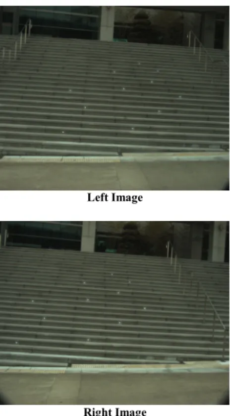
The test was experienced using the car equipped with GPS, IMU, and CCD camera for the GCP in INHA University. Fist of all, the eleven targets were set up on the stairs in front of the library. The coordinates of targets were measured by Total Station, and the images of targets were taken using the CCD camera loaded on the vehicle. The ImageStation, in the Digital photogrammetry system was used to compute the exterior orientation elements of the CCD camera. And then, the information of the formation between IMU and CCD camera and the rotation was gained through the obtain images by Boresight transformation. The following pictures 5 are the images of the target in front of the library.
Fig. 4. The principle of Direct Georeferencing
Left Image
Right Image
Fig. 5. The target in front of the library
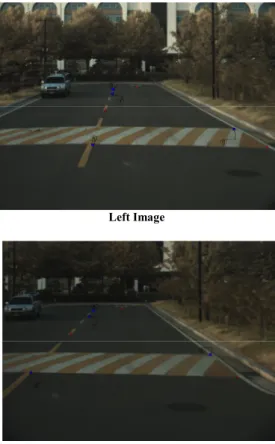
After the car was driving and taking pictures around indoor of the INHA University, the coordinates of the GCP were obtained. The coordinates of the GCP were precisely measured by GPS survey for comparing the accuracy of between Direct Georeferencing and Indirect Georeferencing. Also, the accuracy of the coordinates was compared using the ImageStation and the module of Direct Georeferencing. The following pictures 6 and 7 are the images of object area taken by MMS. The table 1 and 2 are presented the difference between coordinates values obtained by Direct Georeferencing and Indirect Georeferencing and measured values by GPS, and the RMSE(Root Mean Square Error) in each coordinates axes.
Left Image
Right Image
Fig. 6. Images of the object area 1
Left Image
Right Image
Fig. 7. Images of the object area 2
Table 1. The error in Direct Georeferencing
Direct Georeferencing Point
Ex Ey Ez Exyz
1 -0.323 -0.532 -0.345 0.711 2 0.660 1.795 -0.856 2.095 3 -0.456 -1.564 -0.578 1.729 4 0.571 0.985 0.389 1.203 5 0.664 -1.684 -0.801 1.979 6 -0.402 1.326 -0.446 1.455 7 0.543 1.359 -0.591 1.578 8 -0.760 1.755 -0.808 2.076 RMSE 0.564 1.434 0.630 1.665
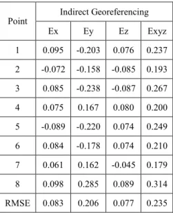
In above tables, the error in Y-axis is larger than other axes.
This reason is presented because MMS has the characteristics that the error of advancing direction is large. In table 1, the Direct Georeferencing has the very large RMSE about the 3-D distance(Exyz). It seems to be affected by the accuracy of IMU.
On the other hand, Indirect Georeferencing is very accurate because the coordinates is computed using the GCP precisely measured by GPS.
5. Conclusion
This test shows that the Indirect Georeferencing is more accurate than the Direct Georeferencing to determine the position. In the case of Direct Georeferencing, the accuracy of IMU is very important element to determine the position. But the IMU used this test has not high level accuracy. Generally, the acquisition of the road facility data should have the accuracy within 30cm~40cm by MMS. If more accurate IMU is used, the accuracy of position is satisfied with this accuracy. As mentioned above introduction, it costs much time and money to measure the GCP. A number of GCP are needed when the Indirect Georeferencing is used for MMS. If the ability of equipment loaded the MMS satisfy the certain condition, the
Direct Georeferencing is much efficient than Indirect Georeferencing for terrestrial photogrammetry.
6. References
[1] Mohamed M.R. Mostafa, 2001, Direct Georeferencing Column:An Introduction, PE&RS, October 2001, pp.1105~1109.
[2] Cameron Ellum, Naser El-Sheimy, 2002, Land-Based Mobile Mapping Systems, PE&RS, January 2002.
[3] Karsten Jacobsen, 2002, Calibration aspects in Direct Georeferencing of frame imagery, ISPRS, pp.82~89.
[4] Korea Institute of Construction Technology, 2001, Development of a Digital Photologging System for Construction of Road Facility Database, Seoul, Daeheung.
Table 2. The error in Indirect Georeferencing
Indirect Georeferencing Point
Ex Ey Ez Exyz
1 0.095 -0.203 0.076 0.237 2 -0.072 -0.158 -0.085 0.193 3 0.085 -0.238 -0.087 0.267 4 0.075 0.167 0.080 0.200 5 -0.089 -0.220 0.074 0.249 6 0.084 -0.178 0.074 0.210 7 0.061 0.162 -0.045 0.179 8 0.098 0.285 0.089 0.314 RMSE 0.083 0.206 0.077 0.235