This study addresses a photogrammetric approach to generate Mars topographic products from mapping data of Mars Global Surveyor (MGS). High-resolution stereo images and laser altimetry data collected from the MGS mission are combined and processed to produce Digital Elevation Models (DEM) and orthoimages. First, altimeter data is registered to high resolution images and considerable registration offset (around 325 m) is discovered on high resolution stereo images. Altimetry data, exterior orientation elements of the camera and conjugate points are used for bundle adjustment to solve this mis-registration and determine the ground coordinates. The mis-registration of altimetry data are effectively eliminated after the bundle adjustment. Using the adjusted exterior orientation the ground coordinates of conjugate points are determined. A sufficient number of corresponding points collected through image matching and their precise 3-D ground coordinates are used to generate DEM and orthoimages. A posteriori standard deviations of ground points after bundle adjustment indicate the accuracy of DEM generated in this study. This paper addresses the photogrammetric procedure: the registration of altimetry data to stereo pair images, the bundle adjustment and the evaluation, and the generation of DEM and orthoimages.
Mars has been continuously explored since 1960s and the various data obtained from the exploration has supported subsequent scientific researches and explorations.
Accurate topographic information is essential and prerequisite for continuing mission planning and various scientific researches. Nevertheless, sufficiently accurate ground control networks for precise topographic mapping are not available. Ground control points on the Martian surface are quite limited both quantitatively and qualitatively. To overcome the difficulties, this study utilizes the mapping data collected from MGS to produce ground control points and topographic mapping products.
MGS, a satellite currently rotating around Mars launched in 1996, has been evaluated as the most successful Mars spacecraft in providing high quality data for topographic mapping to understand Mars. A number of studies on MGS data processing have been published recently. Most recent studies suggest a ~1 m vertical and ~100 m horizontal accuracy of MOLA data based on crossover analysis (Neumann et al. [2001]). Finer regional MOLA DEM up to 1/512° by 1/512° resolution is being produced by the MOLA scientific team. MOLA topography is used as a control network in many recent studies to reference existing DEM, Mars Digital Image Mosaic (MDIM), control networks as well as newly collected MOC images. Diverse results have been reported in early studies. Baratoux et al. [2001] registered Viking DEM to MOLA data to improve the DEM accuracy. Using the extracted orientation information of
MOC images, Kirk et al. [2002] generated high resolution DEM over the selected candidate landing sites from MOC NA images. Rosiek et al. [2001] attempted to use high resolution Viking images together with MOC images when their stereo coverage was not available. In addition to DEM, orthoimages are made over areas of interest using MOLA derived elevation data (Niedermaier et al. [2002]). Anderson and Parker [2002]
used a photoclinometric approach or shape from shading approach to analyze the topographic characteristics of the selected candidate landing sites. Similar analyses were carried out using stereo pairs based on photogrammetric principles (Kirk et al. [2002]).
The purpose of this research is to extract topographic information on Mars based on photographic knowledge accumulated from Earth. Thus, this research is ultimately to generate accurate topographic mapping products:
DEM and orthoimages using MGS mapping data for the MER missions and future Mars exploration missions.
First, altimetry data are registered to high resolution
images. A combined bundle adjustment is then developed
to refine the MGS trajectory data and correct its
inconsistency caused in the registration procedure. Based
on the bundle adjustment and image matching, the 3-D
positions of a large number of ground points are
determined, which are finally used to produce precise and
high resolution DEM and orthoimages.
(2)
2. INSTRUMENT AND DATA: MOC AND MOLA In this research, the data for topographic information on Mars are obtained from MGS. The altitude of MGS is 368-438km and the orbital period is 117.65 minutes.
MGS carries four instruments to collect data on Marsian surface including mapping instruments: Mars Orbital Camera (MOC) and Mars Orbital Laser Altimeter (MOLA).
MOC is a linear pushbroom system including wide angle (WA) cameras and a narrow angle (NA) camera. WA collects 230-500m per pixel resolution images, and NA collects high resolution and panchromatic images with 1- 4m per pixel resolution. Stereopairs of high resolution images used in this research refer to the stereopair list in (Kirk, 2002). Another data for this research is laser altimetry data from MOLA. The objective of MOLA instrument is to understand global topography on Mars.
MOLA transmits laser signals and receives backscattered signals to measure the distance between MGS and Marsian surface.
Three study sites are chosen among MER candidates landing sites: EOS crater, Gusev crater, ISIDIS planitia.
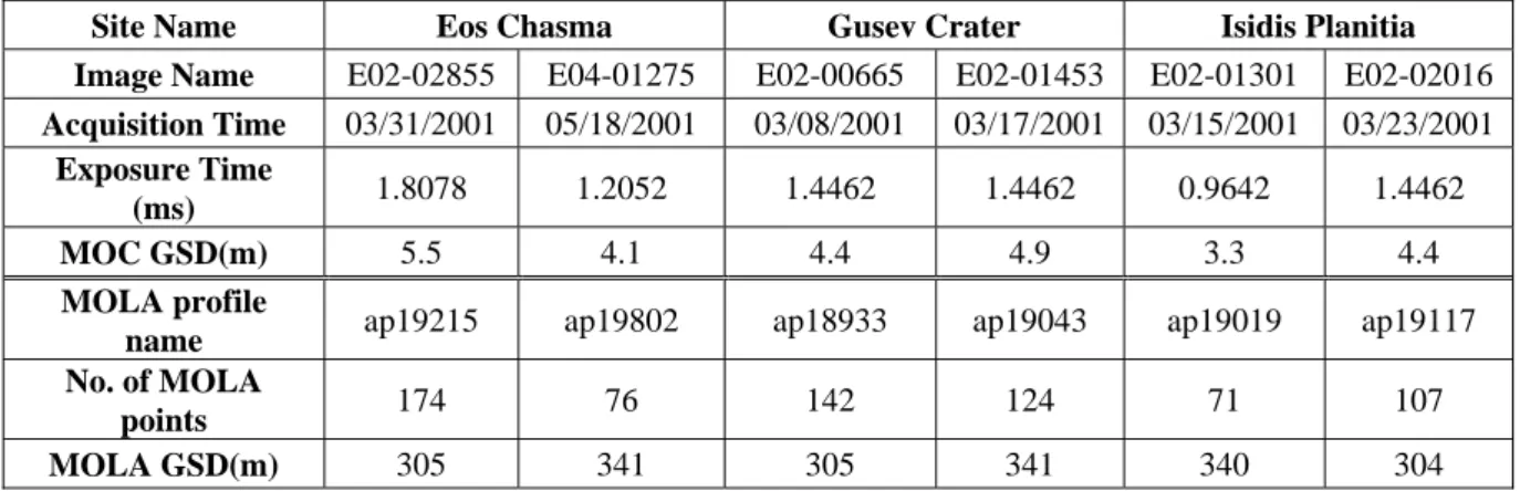
Table 1 lists characteristic of MOC stereo pairs and MOLA points in three study sites. Each study area has two stereo NA images, and two MOLA profiles. All of the MOC images except right EOS chasma image were acquired in March 2001, and the exposure time is the duration exposed to the sensor for one line on one image.
MOC ground sample distance (GSD) of each image is various from 3.3m to 5.5m. The MOLA profile corresponding to an image is called simultaneous MOLA profile because the MOLA profile and the MOC image are recorded at the same orbit and the same.
Table 1. Characteristic of MOC and MOLA
Site Name Eos Chasma Gusev Crater Isidis Planitia Image Name E02-02855 E04-01275 E02-00665 E02-01453 E02-01301 E02-02016 Acquisition Time 03/31/2001 05/18/2001 03/08/2001 03/17/2001 03/15/2001 03/23/2001
Exposure Time
(ms) 1.8078 1.2052 1.4462 1.4462 0.9642 1.4462
MOC GSD(m) 5.5 4.1 4.4 4.9 3.3 4.4
MOLA profile
name ap19215 ap19802 ap18933 ap19043 ap19019 ap19117 No. of MOLA
points 174 76 142 124 71 107
MOLA GSD(m) 305 341 305 341 340 304
3. MOLA REGISTRATION TO MOC Photogrammetric approach using stereo MOC images are mainly based on linear pushbroom properties and MOC exterior orientation. MOLA laser profiles are registered to MOC stereo images using MOC exterior orientation and collinear equations.
MOC exterior orientation elements: satellite position and orientation are extracted from SPICE (S: spacecraft, P:
Planet, I: Instrument, C: C-matrix (rotation), E-Event) library that is provided by NASA. Using the library, the position and orientation of a spacecraft can be calculated based on ephemeris data called kernel. The position of MGS is represented by x, y and z coordinates in Mars- body-fixed system (IAU_Mars), and the orientation of MGS is omega, phi and kappa are the orientation between the MOC NA camera frame and the Mars-body- fixed system. In this process, the relationship between the earth frame, Mars frame, and MGS is established. After extraction of MOC exterior orientation in regular intervals, it is modelled by second order polynomial to get the exterior orientation at each line of an image.
Using ground coordinates of MOLA points and the MOC exterior orientation extracted and collinear equations, the image coordinates corresponding to the ground coordinates of MOLA points are calculated. To visually verify the location, the image coordinates are overlaid with MOC images (Figure 1 (a)). The location of a MOLA point on stereo pair images should be the same.
However, the registration results show the offset in the flight direction. The reason of the offset may come from inconsistent time recorded between MOC and MOLA.
4. BUNDLE ADJUSTMENT
The bundle adjustment is introduced to improve the registration results and determine the MOLA ground coordinates to generate topographic products. A number of conjugate points searched from a matching method are introduced to the bundle adjustment. Additionally, the MOLA ranges and ground coordinates of MOLA are incorporated into the bundle adjustment as measurements.
To determine weights inside the bundle adjustment, a priori standard deviation of each measurement are used.
In this case, MOLA ranges and the image coordinates of
(3)
conjugate points are highly weighted. As contribution of MOLA range and conjugate points, the exterior orientation is adjusted and ground location of points are determined.
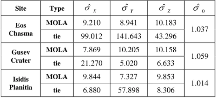
Table 2 shows a posteriori standard deviation calculated from the residuals after bundle adjustment by the law of error propagation. In this table, a posteriori standard deviations of the MOLA points are consistent with their a priori estimation, 10 m. The standard deviation of tie points is about 178 m in Eos Chasma, and it is the largest magnitude of standard deviation for the tie points. For other two sites, the theoretical precision of point determination is estimated to be about 28 m in Gusev Crater and 59 m in Isidis Planitia.
Table 2. a posteriori standard deviation of ground coordinates
As the result of bundle adjustment, the adjusted exterior orientation and the MOLA ground coordinates are used to calculate the image coordinates of MOLA points again to verify the correction. Figure 1 (b) shows the registration result after bundle adjustment in Gusev Crater. The registration offset are effectively removed so the same MOLA point with the same index is project to the same location on both stereo images.
5. RESULT: DEM AND ORTHOIMAGE As the final outcome of this study, DEM and orthoimages are generated with the adjusted results after bundle adjustment. To do so, a sufficient number of corresponding points for describing terrain need to be collected. An image matching method collects a large number of conjugate points in the stereo images. Their ground coordinates are then determined through the intersection using the refined exterior orientation from the combined bundle adjustment. High resolution DEM is created through interpolation of the ground points.
Furthermore, orthorectified images are produced using the generated DEM and MOC images.
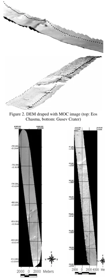
Considering the 4-5m resolution of MOC images, the generated DEM has 10m ground spacing. Two main steps are involved in the DEM generation. The first step is image matching to determine conjugate points in the left and right stereo images. The second is the determination of their 3-D ground coordinates by
intersection. Figure 2 shows generated DEM draped with MOC images in Eos Chasma and Gusev Crater sites.
Orthorectification registers an image to mapping coordinates and removes relief distortion on an image. In this study, collinearity equations and DEM generated in the previous step are used to generate orthoimages. The generated DEM is projected to X and Y coordinates and contains the orthometric height in a grid format. For orthorectification, each DEM cell can be converted to geographic coordinates and body-fixed coordinates. The projected X and Y are from the simple cylindrical projection, while orthometric height is determined from the DEM. The bilinear interpolation is used to determine the orthometric heights from the DEM in accordance with the orthoimage resolution. Figure 3 shows the orthoimages in Eos Chasma and Gusev Crater.
6. CONCLUSION AND DISSCUSION
Mars mapping products are generated through photogrammetric approach accessing and understanding the MGS mapping data in this research. To investigate the mapping capabilities of MGS, MOLA points are registered to MOC stereo images through MOC exterior orientation and collinear equations. The MOLA and MOC data has a nearly constant registration uncertainty of one MOLA GSD (~325 m) along the flight direction.
The combined bundle adjustment can correct the systematic mis-registration. Results from all of the three study sites support this conclusion. Therefore, the refined exterior orientation through the combined bundle adjustment resolves the inconsistency of the MGS mapping data. With adjusted MOC exterior orientation and collinear equations, sufficient ground coordinates of conjugate points are calculated to generate topographic mapping products: DEM and orthoimage.
In this study, only two MOC stereo images for each of the three study sites are used because there were difficulties in finding more MOC stereo images. Further effort should be made to find and include more MOC images in the combined bundle adjustment. It is recommended that the MGS data be combined with other data sources to generate mapping products. In addition, DEM can be compared with different DEM that is generated from different methods to verify the accuracy of topographic mapping products.
7. REFERENCES
Anderson, F. S. and Parker, T. J., 2002. Characterization of MER landing sites using MOC and MOLA. In: The 33rd Lunar and Planetary Science Conference, March 11–15, League City, TX.
Baratoux, D., Delacourt, C., and Allemand, P., 2001.
New local DEM derived from combination of high- resolution Viking Images and the high-precision MOLA data set, In: The 32nd Lunar and Planetary Science Conference, Huston, TX
Site Type σ ˆ
X
σ ˆ
Y
σ ˆ
Z
σ ˆ
0
MOLA 9.210 8.941 10.183 Eos
Chasma tie 99.012 141.643 43.296 1.037 MOLA 7.869 10.205 10.158
Gusev
Crater tie 21.270 5.020 6.633 1.059
MOLA 9.844 7.327 9.853
Isidis
Planitia tie 6.880 57.898 8.306 1.014
(4)
Kirk, R. L., Soderblom, L. A., Howington-Kraus, E., and Archinal, B., 2002. High resolution topomapping of Mars with Mars Orbiter Camera Narrow-angle Images, IAPRS, Vol.34, Part 4, “Geospatial Theory, Processing and Applications”, Ottawa, CDROM.
Neumann, G., Lemoine, F., Rowlands, D., Smith, D. E., and Zuber, M. T., 2001. Crossover analysis in MOLA data processing. Journal of Geophysical Research, Vol.
106, No. E10, pp.23,753-23,768.
Niedermaier, G., Wählisch, M., van Gasselt, S., Scholten, F., Wewel, F., Roatsch, T., Matz, K-D., and Jaumann, R., 2002. A Topographic Image Map of the MC- 18Quadrangle Coprates at 1:2,000,000 using Data obtained from the Mars Orbiter Camera and the Mars Orbiter Laser Altimeter of Mars Global Surveyor, In:
The 33rd Lunar and Planetary Science Conference, March 11–15, League City, TX.
Rosiek, M. R., Kirk, R., and Howington-Kraus, E., 2001.
Mars Orbiter large-scale topographic Maps, In: The 32nd Lunar and Planetary Science Conference, Huston, TX.
Figure 1 (a). MOLA registration before bundle adjustment in Gusev Crater
Figure 1 (b). MOLA registration after bundle adjustment in Gusev Crater
Figure 2. DEM draped with MOC image (top: Eos Chasma, bottom: Gusev Crater)
Figure 3. Orthoimages in Eos Chasma(left) and Gusev