1
A STUDY ON THE DETERMINATION OF THE INSTANTANEOUS FIELD OF VIEW FOR 1-M HIGH
RESOLUTION SATELLITE IMAGE
Doo-Chun Seo, Su-Young Park, Dong-Han Lee, Sun-Gu Lee, Jeong Heon Song, Hyo-Suk Lim
Korea Aerospace Research Institute
45 Eoeun-Dong, Yuseong-Gu, Daejeon 305-333, Korea Phone:+82-42-860-2646, Fax: +82-42-860-2605 {dcivil, sypark, dhlee, leesg, newssong, hslim}@kari.re.kr
ABSTRACT:
In this paper we present a detail approach of the determination of IFOV (Instantaneous Field of View) of high- resolution (1 m) panchromatic satellite image over test site. IFOV is the representative measurements as the determination of the spatial resolution in remote sensed imaging system. It can be defined as some area on the ground with the particular altitude when the satellite acquires the image at any given time.
Especially, spatial resolution of passive sensors primarily depends on their IFOV. The determination of IFOV goes through simple steps of procedure as followings: Firstly, the GSD (Ground Sample Distance) should be computed at each point on the geometrically corrected image. Then, The GSD is converted into the IFOV. So we are going to explain our test procedures and results.
KEY WORDS: GSD, IFOV, Spatial resolution
1. INTRODUCTION
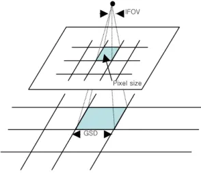
Digital images are often described in terms of their pixel size, but can also be specified in terms of the instantaneous field of view(IFOV), which if the angle determined by the pixel size and the focal length. As shown in Fig. 1, as the focal length decreases or the pixel size increases, the IFOV increases. A larger IFOV means that one pixel covers a larger portion of the scene or, equivalently, that the image will have lower spatial resolution.
Fig 1. The concept of IFOV and GSD
Another measure related to pixel size is the ground sample distance(GSD), which is the projection of the
pixel size onto the ground plane. This is often used erroneously as a synonym for resolution. In fact, the resolution of a digital image is determined by both the sensor geometry and by factors external to the sensor, such as atmospheric conditions, platform motion, etc. The actual resolution may be as good as indicated by the GSD, but in practical applications it is often lower.(Edward M.
Mikhail)
In this study, we are going to calculate IFOV and GSD using panchromatic satellite image with 1m high resolution. The Fig. 2 shows the procedure of IFOV determination.
Fig 2. Flow of procedure Input data preparation
GCP input Conjugate image point input
Geometric correction Calculation of GSD Determination of IFOV
Pixel size IFOV
GSD
2 2. DATA PREPARATION
The test site is located on the playground of high school in Nonsan. For easy detection of image point, the convex mirrors are put on the ground as ground points. The determination of the IFOV for 1-m high resolution image is needed the high-accurated 3D ground coordinates and image coordinates. So, the 3D ground coordinates can be surveyed by using an instrument such as a differential GPS receiver and Total station. The GPS instrument accuracy was better than 10cm±5ppm which means that the instrument was well calibrated and the maximum error measured for ground coordinate was 10cm±5ppm. Fig. 3 shows the used GPS instrument and GPS survey on the test site.
Fig 3. The used GPS instrument and GPS survey
3. GEOMETRIC CORRECTION 3.1 Generation of Ground point
For accurate calculation of GSD, we generate 8 appropriate ground points by GPS survey and Total station triangular survey. Following table indicates the results of GPS and Total station survey.
Table 1. The results of GPS survey
No 1(GPS) No 2(GPS) Height of antenna 1.517 m 1.441 m WGS 84 Latitude 36-10-58.708478 36-11-00.238256 WGS84 Longitude 127-04-37.601671 127-04-42.006180
WGS84 Height 43.099m 43.851m
Table 2. The results of TS triangular survey
The Surveyed Result from TS 3-D Ground coordinates on Bessel TM Middle Origin NO
Horizontal Angle (D.MS)
Vertical Angle (D.MS)
Distance (m)
X (East- West,m)
Y (North- South,m)
Height (m) B6 336.0946 89.5917 39.9603 206995.495 298058.132 18.028 B5 38.4926 90.0724 40.4706 206953.684 298057.083 18.124 B3 139.5753 90.0122 26.2690 206954.584 298109.409 18.047 B1 168.4253 90.0110 53.3863 206956.293 298142.244 18.055 B2 217.1457 89.5258 44.9626 206995.959 298131.315 17.945 B4 267.0917 89.5554 21.7767 206995.582 298096.179 18.011
3.2 Determination of Image point
The convex mirrors are used for accurate pointing while the satellite takes the image over the test site.
Fig 4. The convex mirror
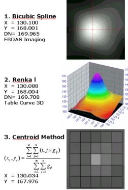
The corresponding image coordinates on the 1-m high resolution image were determined from magnified image of cubic spline interpolation using ERDAS IMAGIME software system and surface fitting of Renka Ⅰalgorithm using TableCurve 3D software and centroid method. Fig.
5 shows the example of result by each method.
Fig 5. Determination method of image point 3.3 Geometric correction
Geometric correction, sometimes called ground registration, is a technique whereby a digital image is processed so that the columns and rows of the resulting product are aligned with north and east in a ground coordinate system.(Paul R. Wolf)
Following equation is used for geometric correction in this study.
Y X
T bx ay Y
T by ax X
+ +
=
+
−
= (1)
In Eqs. (1), x and y are coordinates of points in the ground system. X and Y are coordinates of points in the image that have been obtained by converting form their column and row numbers.
3
0.0 0.2 0.4 0.6 0.8 1.0 1.2 1
2 3
4 5
6
7
8
9
10 11 12 13 14 15 16 17 18 19
20 21
22 23
24
The accuracy by each method of image point determination is following as:
Table 3. RMSE of each method
Column Line Total Determination Methods for
corresponding image center
point RMSE RMSE RMSE Bicubic Spline 0.298 0.452 0.541 TableCurve 3D Renka 1 0.308 0.451 0.546 Centroid Method 0.393 0.513 0.646
4. CALCULATION OF GSD AND IFOV 4.1 Measurement of GSD
The procedure of measuring ground and image points is accomplished to calculate GSD. Fig. 6 indicates the location of total eight convex mirrors in the satellite image. As following, table 4 shows ground points and corresponding image points of convex mirrors.
Fig 6. Location of convex mirrors
Table 4. Ground and image coordinates of convex mirrors Name X Y Z Column Line
B1 206956.293 298142.244 18.055 130.1 168.00 B2 206995.959 298131.315 17.945 170.06 171.2 B4 206995.582 298096.179 18.011 177.75 204.98 B5 206953.684 298057.083 18.124 145.18 251.94 B6 206995.495 298058.132 18.028 185.00 241.44 No1 206974.218 298091.957 17.954 157.35 213.25 No2 206991.107 298038.655 18.001 184.92 261.83
4.2 Calculation of GSD
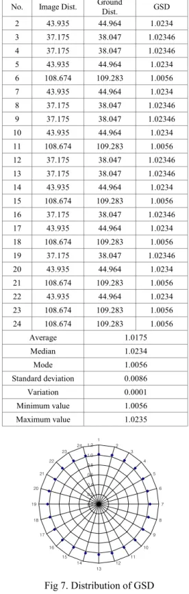
The process of calculating GSD involves three simple steps: First of all, distance between image points is calculated. Second, distance between ground points is measured. Last, GSD is the value to divide ground distance by image distance. Image distance, ground distance, calculated GSD, statistical data are listed in Table 5. Also, distribution of GSD is illustrated in Fig. 7.
Table 5. Calculated GSD each points No. Image Dist. Ground
Dist. GSD 2 43.935 44.964 1.0234 3 37.175 38.047 1.02346 4 37.175 38.047 1.02346 5 43.935 44.964 1.0234 6 108.674 109.283 1.0056 7 43.935 44.964 1.0234 8 37.175 38.047 1.02346 9 37.175 38.047 1.02346 10 43.935 44.964 1.0234 11 108.674 109.283 1.0056 12 37.175 38.047 1.02346 13 37.175 38.047 1.02346 14 43.935 44.964 1.0234 15 108.674 109.283 1.0056 16 37.175 38.047 1.02346 17 43.935 44.964 1.0234 18 108.674 109.283 1.0056 19 37.175 38.047 1.02346 20 43.935 44.964 1.0234 21 108.674 109.283 1.0056 22 43.935 44.964 1.0234 23 108.674 109.283 1.0056 24 108.674 109.283 1.0056
Average 1.0175 Median 1.0234 Mode 1.0056 Standard deviation 0.0086
Variation 0.0001 Minimum value 1.0056
Maximum value 1.0235
Fig 7. Distribution of GSD 4.3 Determination of IFOV
GSD of the ground area sensed by CCD at any instant in time is loosely referred to as the system’s spatial resolution. A small IFOV is obviously desirable to record high spatial detail. And a lager IFOV means a greater quantity of total energy is focused on a detector.(Thomas
B1 B2
B4 NO1 B5 B6
No2
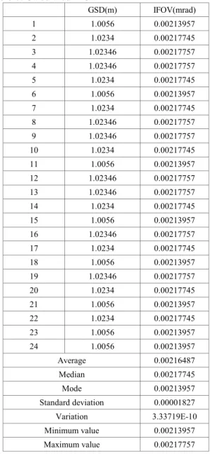
4 M. Lillesand) Here, GSD divided by orbital altitude gives
IFOV as Eq (2).
Altitude Orbital
IFOV = GSD (2)
As the orbital altitude of satellite used in the test is about 470km which is not computed satellite height from osculating orbit but mean alititude from mean orbit, calculated IFOV by Eq. (2) is listed in table 6.
Table 6. Calculated IFOV
GSD(m) IFOV(mrad) 1 1.0056 0.00213957 2 1.0234 0.00217745 3 1.02346 0.00217757 4 1.02346 0.00217757 5 1.0234 0.00217745 6 1.0056 0.00213957 7 1.0234 0.00217745 8 1.02346 0.00217757 9 1.02346 0.00217757 10 1.0234 0.00217745 11 1.0056 0.00213957 12 1.02346 0.00217757 13 1.02346 0.00217757 14 1.0234 0.00217745 15 1.0056 0.00213957 16 1.02346 0.00217757 17 1.0234 0.00217745 18 1.0056 0.00213957 19 1.02346 0.00217757 20 1.0234 0.00217745 21 1.0056 0.00213957 22 1.0234 0.00217745 23 1.0056 0.00213957 24 1.0056 0.00213957
Average 0.00216487 Median 0.00217745 Mode 0.00213957 Standard deviation 0.00001827
Variation 3.33719E-10 Minimum value 0.00213957
Maximum value 0.00217757
5. CONCLUTIONS
The approach of the determination of IFOV of high- resolution satellite image is accomplished over test site.
As both IFOV and GSD are the important measurements as the considering the spatial resolution, this kind of approach have been tested.
In this study, the convex mirrors are used for appropriate high resolution satellite image. To determine IFOV, GSD is computed at each point on the geometrically corrected
image. Then, The IFOV is calculated by GSD. Further efforts will be made to accommodate the calculating IFOV of high resolution satellite image.
6. REFERENCES
Edward, M., 2001. Introduction to Modern Photogrammetry. Wiley, pp. 153-154.
Thomas, M., 1994. Remote sensing and Image Interpretation. Wiley, pp. 355-356.
Paul, R., 2000. Elements of Photogrammetry.
McGrawHill, pp. 189-191.