1. Introduction
In the field of remote sensing, there are a lot of applications which require both high-spatial and high- spectral resolution satellite images. To meet this requirement, most earth resource satellites such as SPOT, IKONOS, QuickBird and KOMPSAT-2 provide high-spatial but low-spectral resolution panchromatic (PAN) image and low-spatial but high- spectral resolution multispectral (MS) image. The reasons behind most satellites do not collect high- spatial resolution MS images directly are two major technical limitations of the incoming radiation energy
to the sensor and the data volume collected by the sensor (Zhang, 2004). In order to obtain a high- resolution MS image from bundle (PAN+MS) images, pan-sharpening technique, therefore, is needed. To provide high quality pan-sharpened images, there have been many studies and many algorithms have been developed. However, all of the pan-sharpening techniques depend on the input images being registered because they all perform operations on corresponding pixels in both images. If the images are not correctly registered, pan- sharpening will use the wrong pixels which are not the corresponding ones and the result will not look
Image Registration for Cloudy KOMPSAT-2 Imagery Using Disparity Clustering
Tae-Young Kim†and Myungjin Choi Korea Aerospace Research Institute (KARI)
Abstract :KOMPSAT-2 like other high-resolution satellites has the time and angle difference in the acquisition of the panchromatic (PAN) and multispectral (MS) images because the imaging systems have the offset of the charge coupled device combination in the focal plane. Due to the differences, high altitude and moving objects, such as clouds, have a different position between the PAN and MS images. Therefore, a mis-registration between the PAN and MS images occurs when a registration algorithm extracted matching points from these cloud objects. To overcome this problem, we proposed a new registration method. The main idea is to discard the matching points extracted from cloud boundaries by using an automatic thresholding technique and a classification technique on a distance disparity map of the matching points.
The experimental result demonstrates the accuracy of the proposed method at ground region around cloud objects is higher than a general method which does not consider cloud objects. To evaluate the proposed method, we use KOMPSAT-2 cloudy images.
Key Words :Image registration, Feature matching, KOMPSAT-2.
Received June 15, 2009; Revised June 20, 2009; Accepted June 22, 2009.
†Corresponding Author: Tae-Young Kim ([email protected])
natural. In other words, the accuracy of image registration directly affects the quality of pan sharpening.
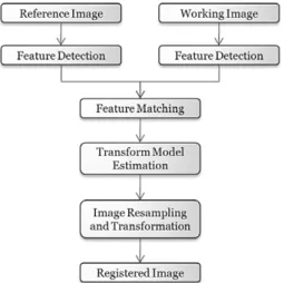
Image registration is the process that determines the best spatial fit between two or more images that overlap the same physical region of the scene being imaged, acquired at the same or at difference date, by identical or difference sensors. A lot of image registration techniques have been developed in remote sensing, medical imaging, computer vision etc (Brown, 1992). Each image registration has its own features due to the diversity of images to be registered and various types of degradations. Nevertheless, the majority of the registration methods consists of four steps: feature detection, feature matching, transform model estimation, image resampling and transformation (Bentoutou et al., 2007; Zitovà and Flusser, 2003).
Like IKONOS and QuickBird, KOMPSAT-2 has the time and angle difference in the acquisition of the PAN and MS image because the satellite imaging systems which are based on charge coupled device (CCD) line sensors have the offset of the CCD combination in the focal plan (Seo et al., 2008;
Jacobsen, 2006). The characteristics cause a displacement if a scene has high altitude objects or moving objects (Latry, 2007). There are some studies to detect moving objects and even to measure their speeds on pan-sharpened images (Yamazaki, 2007;
Etaya et al., 2004). However, if an image registration algorithm chooses high altitude objects or moving objects as matching points in the feature matching step, a misregistration occurs. That is, since clouds are not only high altitude objects and moving objects but also covering a large region with high intensity, it is most likely to extract matching points from cloud boundaries. Therefore, the accuracy of image registration degrades at the ground region around cloud boundary.
The purpose of this paper is to enhance the accuracy of image registration at the ground region around cloud boundary through preventing to select the matching points at cloud boundary (hereafter we call cloud matching points). The method to remove cloud matching points which are selected using cloud mask is already introduced (Kim and Choi, 2009).
However the method failed to remove matching points at thin and small cloud boundary because it is difficult that the cloud mask cover perfectly thin and small clouds. In this paper, we attempt to use the distance disparity of the matching points between the images which are going to be registered. On the distance disparity distribution, we can see that the group of cloud matching points is separated from that of ground matching points.
In order to classify several matching point groups on the distance disparity distribution, we utilize the unsupervised classification. After then, to decide cloud matching point groups from the classification result, we calculate the ratio of cloud matching point in the group using enhanced cloud mask. If the ratio is high, the matching point groups are classified as cloud matching point groups. Since the accuracy of image registration at ground region is more important than at cloud region, we discard classified cloud matching points in feature matching step. To validate our method, we used several KOMPSAT-2 cloudy images.
2. Characteristic of KOMPSAT-2 Sensors
Why has KOMPSAT-2 the time and angle difference in the acquisition of the PAN and MS image? In order to understand the reason of the difference which causes a misregistration, it is needed to know about characteristic of KOMPSAT-2 which is based on CCD-line sensors. The Multi-Spectral
Camera (MSC) on the KOMPSAT-2 has five CCD panels like below Fig. 1. PAN consists of three CCD panels each which has two channels and MS consists of two CCD panels each which has two bands.
If PAN and MS locate exactly at same position in the focal plane, there may be no difference between PAN and MS. However there is realistically a geometrical difference among CCD panels like Fig.
1. This difference causes a different view direction.
Even though the PAN and MS images are matched for reference ground height (H0 in Fig. 2), a
mismatch occurs in other ground height (H1, H2) because of angle difference. Moreover, there is another problem for time difference. In Fig. 2, if PAN sensor acquires image on t1 at P1 ground position, MS sensor acquires image on t2at same position (P1). This means that PAN and MS have different position of moving objects.
3. Methodology
1) Image Registration
Generally, an image registration method consists of the following steps: 1) Feature detection - identifies the relevant features in the two images which include edges, intersection of lines, regions, etc. 2) Feature matching - establishes relationship between the features in the two images. 3) Transform model estimation - determines transformation parameters of the mapping functions using the features being matched. 4) Image resampling and Transformation - geometrically transforms and resamples the sensed image according to the mapping function established. Fig. 3 shows the flowchart of the general image registration.
Fig. 1. MSC front side view.
Fig. 2. Influence of sensor offset in the focal plane. Fig. 3. Flowchart of the general image registration.
For the feature detection, the automated image registration method can be broadly classified into two categories: area-based matching method and feature- based matching method. An area-based matching method uses the gray value of the pixels to describe matching entities. To measure the degree of match, the method usually uses the normalized cross- correlation or least-squares technique. However the method is not well-adapted in multi-sensor image registration, because gray-level characteristics of images to be matched are quite different. A feature- based matching method extracts and then matches corresponding features from two images. The features are significant regions (forests, lakes, fields), lines (region boundaries, coastlines, roads, rivers) or points (region corners, line intersections, points on curves with high curvature). In multi-sensor image registration, the feature-based matching method is suitable than the area-based matching method since the features are invariant to image orientation and are not sensitive to image noise and image resolution (Hong and Zhang, 2007; Starck et al., 1998).
However, if cloud features are chosen in features matching steps, a misregistration occurs because the positions of cloud objects are different between PAN and MS images.
We propose a new image registration method which removes cloud matching points. The proposed method reduces outstandingly the misregistration at ground region around cloud boundary even if cloud objects have a misregistration. Fig. 4 shows the flowchart of the proposed image registration. The proposed method have additional four steps: 1) Cloud Detection, 2) Make Cloud Mask, 3) Classify Cloud Matching Points, 4) Discard Cloud Matching Points.
In the following sections, we describe each additional step of the proposed method.
The proposed method uses a local model as a transform model, due to disparities caused by
difference in altitude and angle. In local model, an optical flow is computed for each pixel according to its neighbors, assuming a plane passes through all of them. After estimating the transform model, a bi- cubic warping is used in image resampling and transformation steps.
2) Cloud Detection & Make Cloud Mask In classifying cloud matching points step, the proposed method uses a binary cloud mask which is made by automatic thresholding algorithm to decide cloud matching point groups. The automatic thresholding algorithm is automatically to select an optimal gray-level threshold values for separating objects of interest in an image from the background based on their gray-level distribution. Several automatic thresholding algorithms have been studied in many applications (Sezgin and Sankur, 2004).
These algorithms are selected as the purpose of processing and the characteristic of the image.
Several methods based on the automatic thresholding Fig. 4. Flowchart of the proposed image registration.
algorithm are studied in remote sensing field (Liu and Xu, 2005; Panem et al., 2005; Soo et al., 2004;
Chang et al., 2001).
We use Otsu algorithm (Otsu, 1979) which is simple, fast and effective to calculate threshold value automatically. The algorithm finds valley position in bimodal histogram and decides a threshold value at valley position. To find the valley position, the algorithm searches for the optimum threshold that minimizes the intra-class variance, defined as a weighted sum of variances of the two classes:
s2w(t) = q1(t)s12(t) + q2(t)s22(t) where
q1(t) = P(i)
q2(t) = P(i)
s12(t) = [i_m1(t)]2
s22(t) = [i_m2(t)]2
m1(t) =
m2(t) =
Because the characteristic of the scene which has clouds is to have two peaks in MS1 band (see Fig. 5), the Otsu algorithm is appropriate for finding the optimum threshold.
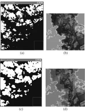
The result binary image of Otsu method is Fig. 6-a.
White region covers almost cloud region. However white region does not cover perfectly boundary of the cloud (see Fig. 6-b). In order to cover mostly the boundary of the cloud as well as cloud region, we made the cloud mask as following steps.
1) Divide the image into blocks
2) Decide whether a block is cloud or not
3) Extend the cloud block to cover sufficiently the boundary of the cloud
The Fig. 6-c and 6-d show the created binary cloud mask through these steps.
3) Classify and Discard Cloud Matching Points
In order to classify and discard cloud matching points, the proposed method executes the following five steps : 1) Calculate the distance disparity of the matching points, 2) Clustering the matching points, 3) Measure the cloud matching points ratio of the iP(i)
q2(t)
SI i=t+1
iP(i) q1(t)
St i=1
P(i) q2(t)
SI i=t+1
P(i) q1(t)
St i=1
SI i=t+1
St i=1
Fig. 5. (a) KOMPSAT-2 cloudy MS1 image; (b) Histogram of cloudy scene.
(a) (b)
Fig. 6. Binary cloud mask.
(c)
(a) (b)
(d)
clusters, 4) Determine the cloud clusters, 5) Discard cloud matching points.
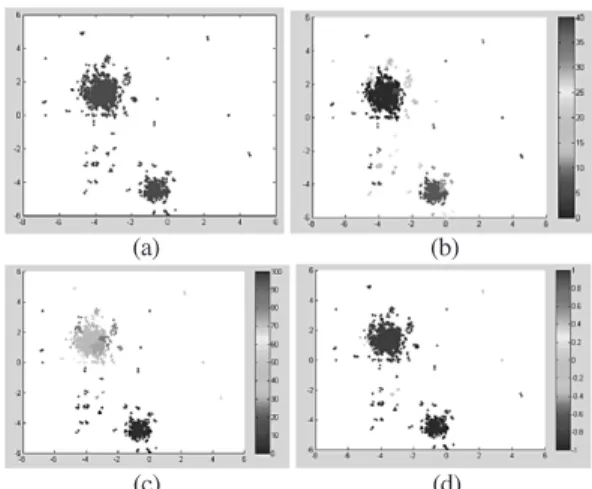
Step 1) The distance disparity of the matching points is the pixel position difference of matching points between PAN and MS. If the scene has cloud objects, the distance disparity values can be divided into two categories, because the distance disparity of the cloud matching points is larger than the ground matching points. Fig. 7-a shows the distance disparity distribution.
Step 2) The proposed method uses sequential algorithm which is one of clustering algorithms since we have no classified sample and no information of the number of clusters. The sequential algorithm is simple and determines automatically the number of clusters (Theodoridis and Koutroumbas, 2006). Fig.
7-b shows the result of clustering which has forty clusters. The matching points in the same cluster have similar height and velocity.
Step 3) We measure the ratio of the matching points which are in cloud mask about every clusters.
Fig. 7-c shows the ratio. The bright colors mean that the probability to be a cloud cluster is high and the cool colors mean that the probability is low.
Step 4) If the ratio of cluster is higher than upper threshold ratio, the cluster is regarded as the cloud cluster and if the ratio is lower than lower threshold ratio, the cluster is regarded as the ground cluster. If the ratio is between upper and lower threshold ratio, the cluster is regarded as undecided cluster. In this study, we define the upper threshold ratio is 30% and the lower threshold ratio is 10%. Fig. 7-d shows the classification of the clusters. After calculating the mean distance between the undecided clusters and the decided clusters, if a undecided cluster is close to cloud clusters, the undecided cluster is decided as the cloud cluster otherwise decided as the ground cluster.
Step 5) To prevent that the cloud matching points are used in features matching steps, we remove the
cloud matching points.
4. Experimental Results
To exhibit the practicality of the proposed image registration method, we present illustrative results.
We choose the cloudy KOMPSAT-2 scene of which the orbit number is 11595, the path/raw is 1004/1232.
The PAN and MS images was taken simultaneously.
Fig. 8 shows the overlaid image which displays the MS1 band image, the cloud mask and matching points. To prevent misregistration, the matching points on cloud objects have to be removed. There are the red matching points which are removed by the Fig. 7. The distance disparity distribution.
(c)
(a) (b)
(d)
Fig. 8. The discarded and final matching points.
proposed method. Although cloud mask does not cover small and thin clouds, the proposed method almost removes the matching points on the cloud objects because the matching points are treated as the cluster. This result shows that the proposed method is more effective than the former method which removes only matching points in the cloud mask.
To see the accuracy of the image registration result, we present the overlaid image which consists of red and blue channel with registered PAN and green channel with MS1. Fig. 9-a is the result of the former method which does not consider cloud objects. Although cloud objects have no misregistration, the distortion arises at ground regions nearby cloud objects because the cloud matching points affect the ground regions matching. The maximum distance of the distortion is 27.3130 pixels
for Fig. 9-a. Fig. 9-b is the proposed method result. In this result, there is no distortion at the ground regions because the proposed method uses only the ground matching points.
5. Conclusion
In this paper, we propose a new approach for the image registration of cloudy high resolution image.
The proposed method shows how to discard the matching points of cloud objects which cause a mismatch. The experimental results show that the accuracy of the proposed method is high at ground region around cloud objects. In addition, the proposed method may be able to be applied to other high resolution satellite data.
In future work, the proposed method will be tested on more datasets which have variety cloud pattern, sand and snow. Moreover, in other to classify precisely cloud matching points, we will concentrate on studying more suitable automatic thresholding technique and classification technique.
References
Bentoutou, Y., Taleb, N., Bounoua, A., Kpalma, K.
and Ronsin, J., 2007. Feature Based Registration of Satellite Images, ICDSP 2007.
Brown, L. G., 1992. A survey of image registration techniques, ACM computing Surveys, 24(4):
325-376.
Chang, C. W., Lim, K. H., and Liew, S. C., 2001.
Cloud mask for MODIS, Asian Conference on Remote Sensing, 5-9 November 2001, Singapore.
Etaya, M., Sakata, T., Shimoda, H., and Matsumae, Y., 2004. An Experiment on Detecting Fig. 9. The distance disparity distribution.
(a)
(b)
Moving Objects Using a Single Scene of QuickBird Data, Journal of the Remote Sensing Society of Japan, 24(4): 357-366.
Hong, G. and Zhang, Y., 2007. The image registration technique for high resolution remote sensing image in hilly area, Geoscience and Remote Sensing Symposium, 2007. IGARSS 2007. IEEE International 23- 28 July 2007 Page(s): 377-380.
Jacobsen, K., 2006. Calibration of Optical Satellite Sensors, International Calibration and Orientation Workshop EuroCOW 2006.
Casteldefels, 2006, 6 S., CD.
Kim, T. Y. and Choi, M., 2009. Image Registration Method for KOMPSAT-2 cloud imagery, KSRS2009.
Latry, Ch., Panem, C., and Dejean, P., 2007. Cloud Detection with SVM technique, Geoscience and Remote Sensing Symposium, IGARSS 2007. IEEE International 23-28 July 2007 Page(s): 448-451.
Liu, J. and Xu, J., 2005. An Automated, Dynamic Threshold Cloud Detection Algorithm, ITSC XIV Beijing, China 25-31 May 2005.
Otsu, N., 1979. A threshold selection method from gray level histograms, IEEE Trans. Syst. Man Cybern. SMC-9, 62-66-1979.
Panem, C., Baillarin, S., Latry, C., Vadon, H., and Dejean, P., 2005. Automatic Cloud Detection on High Resolution Images, Geoscience and Remote Sensing Symposium, IGARSS ’05.
Proceedings. 2005 IEEE International,
Volume: 1, On page(s): 4 pp.
Seo, D. C., Yang, J. Y., Lee, D. H., Song, J. H., Lim, and H. S., 2008. KOMPSAT-2 direct sensor modeling and geometric calibration/
validation, ISPRS2008.
Sezgin, M. and Sankur, B., 2004. Survey over Image Thresholding Techniques and Quantitative Performance Evaluation, Journal of Electronic Imaging, 13: 146-165.
Soo, M. L., Liew, C., and Kwoh, L. K., 2004.
Automated Production of Cloud-free and Cloud Shadow-free Image Mosaics from Cloudy Satellite Imagery, Proc. XXth Congress of the International Society for Photogrammetry and Remote Sensing, 15 - 23 July 2004, Istanbul, Turkey.
Starck, J.-L., Murtagh, F., and Bijaoui, A., 1998.
Image processing and data analysis, The multiscale approach 163 - 197, Cambridge University Press; 1 edition (July 13, 1998).
Theodoridis, S. and Koutroumbas, K., 2006. Patten Recognition, 3rd Ed., Academic Press.
Yamazaki, F., Wen Liu, and Vu, T. T., 2007. Speed Detection for Moving Objects from Digital Aerial Camera and QuickBird Sensors.
Zhang, Y., 2004. Understanding Image Fusion, Photogrammetric Engineering and Remote Sensing, 70(6): 653-760.
Zitovà, B., Flusser, J., 2003. Image registration methods: a survey, Image and Vision Computing, 21: 977-1000.