Effects of the Angulation of Orthodontic Mini-Implant as an Indirect Anchorage : A Three-Dimensional Finite Element Analysis
Min-Ji Kim, DDS,MSD,PhD,
1Yong-Jin Park, DDS,MSD,
2Sun-Hyung Park, DDS,MSD,PhD,
3Youn-Sic Chun, DDS,MSD,PhD,
41
Assistant professor,
4Professor, Division of Orthodontics, Department of Dentistry, School of Medicine, Ewha Womans University
2
Former student, Department of Orthodontics, Graduate School of Clinical Dentistry, Ewha Womans University
3
Visiting scholar, Division of Orthodontics, Department of Dentistry, University of Nebraska medical center The purpose of this study was to investigate the displacement and pattern of stress distribution on periodontal ligaments of maxillary first and second molar, and on orthodontic mini-implant (OMI) surface, according to three different insertion angles to the bone surface of OMI using Dragon helix appliance, which is a newly introduced scissors-bite correcting appliance.
OMI were placed between second premolar and first molar with three different insertion angles (45, 60, 90 degrees).
Displacement and maximum stress distribution area (MSDA) were analyzed by finite element analysis.
When the insertion angle to the alveolar bone surface was 90 degrees, maxillary first and second molar both exhibited MSDA at the palatal root apex. Maxillary first molar did not show any significant displacement, while the second molar exhibited intrusive and palatal displacement. On the OMI, as the insertion angle decreased, the MSDA shifted towards the tip, and the amount of displacement had increased.
When the OMI was inserted at a 90 degree angle, anchor loss was minimized and scissors-bite correcting effect was maximized.
Key word: orthodontic mini-implant (OMI), finite element analysis, insertion angulation
(
Journal of Dental Rehabilitation and Applied Science
2010:27(3):293~304)Correspondence to : Youn-Sic Chun DDS, MSD, PhD, Professor, Division of Orthodontics
Department of Dentistry, School of Medicine, Ewha Womans University, Seoul, Korea911-1, Mokdong, Yang Cheon-Gu, Ewha Womans University, Mokdong Hospital, Seoul, Korea Tel: +82-2-2650-5112, Fax: +82-2-2655-0984, E-mail: [email protected]
Received: May 20, 2011, Last Revision: August 23, 2011, Accepted: September 25, 2011
INTRODUCION
There have been many attempts to correct scissors-bite, but the treatment has been difficult due to the extruded and buccally inclined upper molar and lingually inclined lower molar. Attachments on the palatal surface of the upper molar and buccal surface of the lower molar causes occlusal interference, which makes the treatment of scissors- bite difficult.
1In order to correct scissors-bite, intrusion and palatal movement of the affected upper molar should be considered. Previous studies introduced treatment methods such as using the upper third molar after extracting upper second molar,
2,3using criss-cross elastics, modified transpalatal arch,
4molar intrusion arch,
5and precision lingual arch.
6These treatment methods has disadvantages such as requiring surgical procedure, extrusion of affected teeth which triggers traumatic occlusion or anterior openbite, requiring the patient's cooperation, and loss of anchorage.
To reduce the adverse effect during scissors-bite correction, Dragon helix system combined with indirect skeletal anchorage system has been introduced recently.
1This system consists of helix
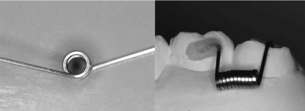
Fig. 1. Application of Dragon helix, for tipping and intruding the maxillary second molar.
with two arms, which are about 5mm in length, made by .016"×.022" stainless steel wire and the two arms set in 110 degrees (Fig 1). One arm attaches to the buccal side of maxillary first molar, while the other to the occlusal of second molar. This device produces intrusive and palatal movement of the maxillary second molar without causing any occlusal interferences. Anchor tooth is connected to the orthodontic mini-implant (OMI) by a rigid wire such as .018"×.025" stainless steel. These components serves as an indirect skeletal anchorage.
The purpose of this study was to investigate displacement and pattern of stress distribution on periodontal ligaments of maxillary first and second molar, and on OMI surface, according to three different insertion angles (45°, 60°, and 90°) of OMI, and to determine the most effective insertion angle, during scissors-bite correction using Dragon helix appliance,
MATERIALS & METHODS
Scissors-bite on the second molar, which was
extruded and buccally inclined, of the upper left
quadrant model was fabricated with a typodont.
Element type Young’s modulus (g/mm
2) Poisson’s ratio
Teeth Solid 45 2E6 0.3
Periodontal ligament Solid 45 5.0 0.3
Alveolar bone Solid 45 2E5 0.3
Splinting wire (.018"×.025") Beam 4 2E7 0.3
Dragon helix (.016"×.025") Beam 4 1.1E7 0.3
Table Ⅰ. Element type, Young’s modulus and Poisson’s ratio of material compounds of element models.
Node numbers of OMI Element numbers of OMI Total node numbers Total element numbers
OMI 45° 2666 9666 88454 408877
OMI 60° 2734 10010 88297 408535
OMI 90° 2392 8571 87476 404560
T6 6494 28196
PDL of T6 4616 4540
T7 4722 20195
PDL of T7 3288 3255
* PDL : periodontal ligament, OMI : orthodontic mini implant, T6 : maxillary first molar, T7 : maxillary second molar
Table Ⅱ. Elements and numbers of node.
After three-dimensional (3D) scanning, 3D CAD (Computer Aided Design) data was acquired by CATIA V5 (Computer Aided Three Dimensional Interactive Application Version 5) (Dassault Systmes, S.A., France) program. Using Hyper-Mesh 8.0 (Altair Corp. Michigan. USA) periodontal ligaments (PDL) were made from root surfaces.
Young's moduli and Poisson's ratio values of alveolar bone, PDL, connecting wire, and Dragon Helix were given as they were assumed as an isotropic homogeneous linear elastic model (Table
Ⅰ). Table Ⅱ shows the elements and numbers of nodes.
Finite element model of the OMI, which was 9mm in length with 5.7mm spiral part, 0.6mm pitch, and 5.7 degree of taper angle, was also made by CATIA V5.
Dragon helix was shaped into a spring of 2mm in diameter with 11 turns made by .016"×.022"
stainless steel wire, which was placed at the crown of the maxillary first and second molar. Activation of the Dragon Helix was simulated by fixing one arm to the overcorrected second molar using Constraint Equation of Ansys
Ⓡ(ANSYS, Canonsburg, USA).
For indirect anchorage, the OMI and first molar
were connected with .018"×.025" stainless steel wire, First and second molar were than connected by Dragon helix. The OMI was inserted between maxillary second premolar and first molar. The OMI was inserted in an angle of 45°, 60°, and 90° to the alveolar bone surface in group 1, 2, and 3, respectively. Stress distribution and displacement of the periodontal ligament of maxillary first and second molar and the surface of OMI were analyzed by finite element analysis with Ansys
Ⓡversion 11 and HP workstation XW 6400 (Zeon 1.6Ghz *2 CPU, Ram 4G)
Von Mises stress of the OMI and maxillary first and second molar were reported to evaluate the stress distribution of the objects. In the displacement graph, axis of the OMI (from center of the head to screw end tip) and upper maxillary first and second molar (from palatal cusp tip to palatal root apex) were used to observe the amount and pattern of displacements of the objects.
RESULTS
1. Maximum stress distribution area (MSDA)
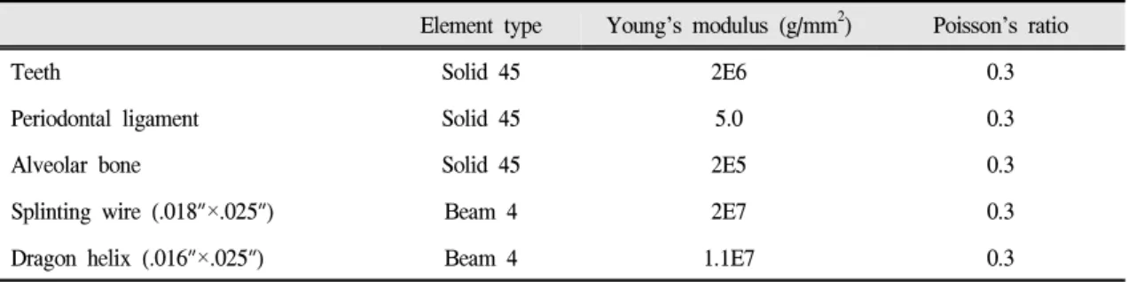
Stress distribution shown on the PDL of the maxillary first molar is shown on Fig 2. The color changes from blue to red indicates stress increase.
The MSDA was on the buccal apex in group 1 and 2, whereas on the palatal apex in group 3 of the maxillary first molar. MSDA of the maxillary second molar was also on the palatal root apex in group 3 (Fig 3), which indicated intrusive movement.
Minimal stress distribution area of the maxillary second molar was on the root apex in group 1 and 2, while on the middle of the buccal root in group 3 (Fig 3). This indicated that controlled tipping was shown in group 1 and 2, whereas uncontrolled
tipping was shown in group 3. MSDA was on the head of OMI in group 3, but it shifted towards the tip from group 2 to group 1 (Fig 4). This implied that greater displacement could be detected as the insertion angle of OMI decreased from 90° to 45°.
2. Displacement
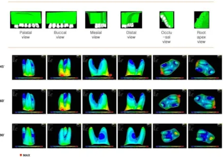
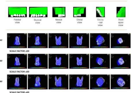
The maxillary first molar crown showed distal tilting in group 1 and 2, with the center of rotation on the furcation area, while only distal movement of the root was detected in group 3. (Fig 5 and 6) From mesial view, the maxillary first molar showed buccal controlled tipping in group 1 and 2, while minor buccal translation was shown in group 3. (Fig 6) In group 1 and 2, the maxillary second molar had expressed controlled tipping displacement, with the center of rotation at the palatal root apex.
Uncontrolled tipping movement of the maxillary second molar was shown in group 3 with the center of rotation at the furcation area (Fig 7). From mesial view, the second molar had the greatest amount of palatal displacement in group 3 (Fig 8). In group 1 and 2, there were almost no root displacement in the second molar, while the root had buccal and intrusive displacement in group 3 (Fig 8).
In the 500 and 1000 times magnified figure and graph, (Fig 9 and 10) minor displacement of the head of the OMI was expressed on coronal area in group 1 and 2, and on apical area in group 3. The displacement of OMI was the least in group 3.
DISCUSSION
OMI has provided several advantages in the
treatment of scissors-bite,
7such as preventing loss of
anchorage, traumatic occlusion and anterior openbite
caused by unexpected extrusion of the affected
tooth.
8The anchor can be controlled by either
Fig. 2. Stress distribution of the periodontal ligament of the maxillary first molar, according to the insertion angle of OMI. As the force increases the color changes from blue to red.
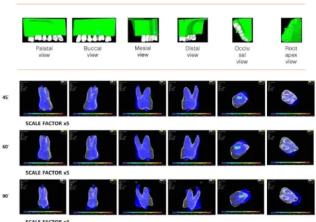
Fig. 3. Stress distribution of the periodontal ligament of the maxillary
second molar, according to the insertion angle of OMI. As the force
increases the color changes from blue to red.
Fig. 4. Stress distribution of OMI, according to the placement angle. As the force increases the color changes from blue to red.
Fig. 5. Displacement of the maxillary first molar, according to the insertion
angle of OMI. White color is before, and blue is after force
application on the tooth.
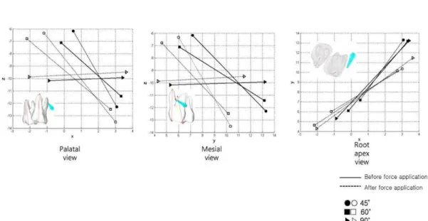
Fig. 6. Graph for displacement of the maxillary first molar in palatal, mesial, and apical view (from palatal cusp tip to palatal root apex, 50 times magnified). Larger X, Y, and Z value indicates mesial, buccal, and apical movements, respectively.
Fig. 7. Displacement of the maxillary second molar, according to the
insertion angle of OMI. As the force increases the color changes
from blue to red.
Fig. 8. Graph for displacement of the maxillary second molar (from palatal cusp tip to palatal root apex, 50 times magnified). Larger X, Y, and Z value indicates mesial, buccal, and apical movements, respectively.
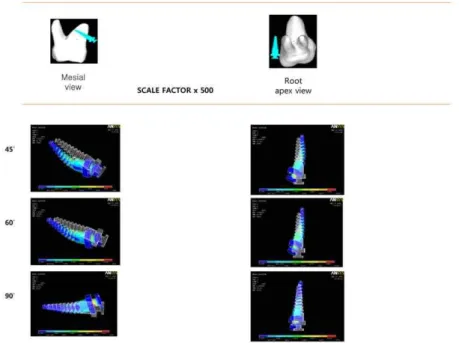
Fig. 9. Displacement of the OMI (500 times magnified). White color is
before, and blue is after force application on the OMI.
Fig. 10. Graph for displacement of OMI from center of the head to screw end tip (1000 times magnified). Larger X, Y, and Z value indicates mesial, buccal, and apical movements, respectively.
direct
9-11or indirect method.
12,13When orthodontic force is loaded to the OMI directly, it is called direct anchorage. It has disadvantages such as difficulties in controlling torque and rotation, requiring additional OMI, and placement difficulties due to the limitation of anatomical structures. Due to such disadvantages in direct anchorage system of OMI, indirect anchor system was introduced.
1Many previous studies were done regarding the stability of OMI,
14,15and there were some recommended insertion angle of the OMI to prevent root damage and to increase surface contact.
16-19The recommended insertion angles of OMI in the maxillary molar area were between 30-40 degrees,
18,19and such angulated insertions were found to have no significant influences on clinical success rate.
20Previous study considering the position of OMI in correcting scissors-bite of the maxillary molar had been done but had not
considered the insertion angle of the OMI.
21In this study, insertion angle of 90 degrees showed the most favorable stress distribution aspect and least displacement to the maxillary first molar, which was the anchor tooth. MSDA of the maxillary second molar was on the palatal root apex when the insertion angle of OMI was 90 degrees, MSDA indicating efficient intrusion. Also, palatal crown displacement was greatest when the OMI was inserted at an angle of 90 degrees. As the insertion angle of OMI decreased, the MSDA shifted gradually towards the tip and the amount of displacement had increased. However, since the amount of displacement was interpreted with the graphs magnified by 500 and 1000 times, the actual differences are expected to be minute in clinical practice.
Methods of measuring stress distribution includes
photoelastic analysis,
22strain gauge analysis, laser
holography analysis, and finite element analysis.
Finite element analysis can interpret stress distribution and initial displacement by fabricating a three dimensional model on the computer and produce quantitative graphical results.
23-25However, finite element analysis has its own limitation due to difficulties in simulating anatomical and biological characteristics of individuals. Finite element analysis calculates only the difference of initial loading moment and this does not include long term reaction.
23-25Therefore the results can differ from the actual oral environment, which is constantly influenced by masticatory force, anatomical structure, and other biological features. Such long term reaction, including influences of other oral environments requires further studies.
CONCLUSION
Three dimensional finite element analysis of Dragon helix combined with indirect anchorage has exhibited more efficient anchorage and scissors-bite correcting movement of the affected molar when the OMI was placed at an angle of 90 degrees.
REFERENCES
1. Yun SW, Lim WH, Chong DR, Chun YS. Scissors- bite correction on second molar with a dragon helix appliance. Am J Orthod Dentofacial Orthop 2007;
132:842-847.
2. Moffitt AH. Eruption and function of maxillary third molars after extraction of second molars. Angle Orthod 1998;68:147-152.
3. Orton-Gibbs S, Orton S, Orton H. Eruption of third permanent molars after the extraction of second permanent molars. Part 2: Functional occlusion and periodontal status. Am J Orthod Dentofacial Orthop 2001;119:239-244.
4. Kucher G, Weiland FJ. Goal-oriented positioning of
upper second molars using the palatal intrusion technique. Am J Orthod Dentofacial Orthop 1996;110:466-468.
5. Chun YS, Woo YJ, Row J, Jung EJ. Maxillary molar intrusion with the molar intrusion arch. J Clin Orthod 2000;34:90-93.
6. Burstone CJ. Precision lingual arches. Active applications. J Clin Orthod 1989;23:101-109.
7. Chae JM. Indirect palatal skeletal anchorage (PSA) for treatment of skeletal Class I bialveolar protrusion.
Korean J Orthod 2004;34:458-464.
8. Chun YS, Row J, Suh MS, Park IK. An experimental study on the dymamic tooth moving effects of two precision ligual arches(PLA) for correction of posterior scissor bite by the Calorific machine Korean J Orthod 1998;24:721-733.
9. Park HS, Kwon OW, Sung JH. Uprighting second molar with micro-implant anchorage. J Clin Orthod 2004;38:100-103.
10. Park HS, Kyung HM, Sung JH. A simple method of molar uprighting with micro-implant anchorage. J Clin Orthod 2002;36:592-596.
11. Kyung HM, Lim JK, Park YC. The use of miniscrew as an anchorage for the orthodontic tooth movement.
Korean J Orthod 2001;31:415-424.
12. Yun SW, Lim WH, Chun YS. Molar control using indirect mini-screw anchorage. J Clin Orthod 2005;39:661-664.
13. Kyung SH, Choi HW, Kim KH, Park YC. Bonding orthodontic attachment to miniscrew heads. J Clin Orthod 2005;39:348-353.
14. Miyawaki S, Koyama I, Inoue M, Mishima K, Sugahara T, Takano-Yamamoto T. Factors associated with the stability of titanium screws placed in the posterior region for orthodontic anchorage. Am J Orthod Dentofacial Orthop 2003;124:373-378.
15. Deguchi T, Nasu M, Murakami K, Yabuuchi T, Kamioka H, Takano-Yamamoto T. Quantitative evaluation of cortical bone thickness with computed tomographic scanning for orthodontic implants. Am J Orthod Dentofacial Orthop 2006;129:721 e727-712.
16. Kim HJ, Yun HS, Park HD, Kim DH, Park YC.
Soft-tissue and cortical-bone thickness at orthodontic
implant sites. Am J Orthod Dentofacial Orthop 2006;130:177-182.
17. Kim SH, Yoon HG, Choi YS, Hwang EH, Kook YA, Nelson G. Evaluation of interdental space of the maxillary posterior area for orthodontic mini-implants with cone-beam computed tomography. American Journal of Orthodontics and Dentofacial Orthopedics 2009;135:635-641.
18. Park HS. An anatomical study using CT images for the implantation of micro-implants. Korean J Orthod 2002;32:435-441.
19. Kyung HM, Park HS, Bae SM, Sung JH, Kim IB.
Development of orthodontic micro-implants for intraoral anchorage. J Clin Orthod 2003;37:321-328.
20. Park YC, Kim JK, Lee JS. Atlas of contemporary orthodontics. Seoul: Shinheung international 2006.
21. Kim MJ, Park SH, Kim HS, Mo SS, Sung SJ, Jang GW et al. Effects of the position of orthodontic mini- implant in Dragon helix appliance : a three- dimensional finite element analysis. Korean J Orthod 2011;41:191-199.
22. Chun YS. A photoelastic study on the initial stress distribution by 3 types of molar uprighting spring.
Korean J Orthod 1994;24:709-719.
23. Park CK, Yang YS. A three-dimensional finite element analysis on the location of center of resistance during intrusion of upper anterior teeth 1997;27:259-272.
24. Byoun NY, Nam EH, Yoon YA, Kim IK. Three- dimensional finite element analysis for stress distribution on the diameter of orthodontic mini- implants and insertion angle to the bone surface.
Korean J Orthod 2006;36:178-187.
25. Koo BC, Sohn BW. An analysis of stress distribution in the case of unilateral molar expansion with precision lingual arch by finite element method.
Korean J Orthod 1994;24:721-733.
교정용 미니임플란트의 식립각도에 따른 간접골성 고정원의 효과에 대한 유한요소 해석
1
조교수,
4교수, 이화여자대학교 의학전문대학원 치과학교실 교정과
2
대학원 졸업생, 이화여자대학교 임상치의학대학원 임상교정치의학 전공
3
교환교수, Division of Orthodontics, Department of Dentistry, University of Nebraska medical center
김민지
1․박영진
2․박선형
3․전윤식
5구치부 가위교합을 개선하기 위한 여러 방법 중, 교정용 미니임플란트(OMI)와 조합된 Dragon helix를 이용한 방법 이 이전에 소개된 바 있으며 이는 간접 골성고정원의 역할이 중요하다. 이에 본 연구에서는 간접골성고정원으로 사용된 OMI의 식립각도에 따라 나타나는 구치부의 치근에 나타나는 응력분포와 OMI의 표면에서의 응력 분포 및 변위를 유한요소 해석으로 비교하고자 하였다. 상악 제1대구치와 상악 제2소구치의 치근 사이에 OMI의 식립 각도 를 골 표면에 대하여, 45°, 60°, 90°으로 변화시키면서 최대응력분포와 변위를 관찰하였다. OMI의 식립 각도가 90°
일 때 상악 제1대구치와 상악 제2대구치의 구개 치근첨에 최대응력분포가 나타났고, 상악 제1대구치에서는 협측으 로 변위의 양이 가장 적게 나타났으며, 상악 제2대구치에서는 함입 및 구개측으로의 변위량이 가장 크게 나타났다.
OMI에서는 식립각도가 감소됨에 따라 최대 응력분포가 나사첨 부분으로 이동되었으며, 그에 따라 OMI의 변위량은 증가하였다. 이상의 결과로 OMI의 식립각도가 90°일 때 고정원의 역할이 최대가 되었으며, 구치부 가위교합의 개선 효과가 가장 크게 나타남을 알 수 있었다.
주요어: 교정용 미니임플란트 (OMI), 유한요소해석, 식립각도
교신저자:
전윤식 교수
이화여자대학교 의학전문대학원 치과학교실 교정과 서울시 양천구 목5동 911-1 이대목동병원 치과 교정과
Tel: 02-2650-5112, Fax: 02-2650-5764, E-mail: [email protected]
원고접수일: 2011년 05월 20일, 원고수정일: 2011년 08월 23일, 원고채택일: 2011년 09월 25일