Introduction
Because of the absence of periodontal ligaments, osseointegrated implants, unlike natural teeth, react biomechanically in a manner different from occlusal loading. Therefore, dental implants are considered to be prone to occlusal overload. This is considered to be one of the potential causes of bone loss around implant and fracture of implant/implant prosthesis.
1It has been argued that giving a slight offset to the central implant in a 3-unit implant prosthesis is bio-
mechanically advantageous.
2-4Marginal bone resorp- tion for implant-supported prostheses with cantilever arms has been reported, and there is concern over excessive stress concentration.
5-7The purpose of this study was to evaluate effects of loading direction and number of implants in a 3-unit implant support prosthesis with different im- plant positions on stress distribution in the implant, prosthesis, and the supporting bone based on 3D finite element analysis.
*Correspondence to: Hongso Yang
Professor, Department of Prosthodontics, School of Dentistry, Chonnam National University, 33 Youngbong-ro, Buk-gu, Gwangju, 61186, Republic of Korea Tel: +82-62-530-5823, Fax: +82-62-530-0130, E-mail: [email protected] Received: July 1, 2020/Last Revision: July 8, 2020/Accepted: July 25, 2020
effects of implant alignment and load direction on mandibular bone and implant: finite element analysis
Hyunju Chung
1, Chan Park
2, Kwi-Dug Yun
2, Hyun-Pil Lim
2, Sang-Won Park
2, Hongso Yang
2*
1
Department of Periodontology, School of Dentistry, Chonnam National University, Gwangju, Republic of Korea
2
Department of Prosthodontics, School of Dentistry, Chonnam National University, Gwangju, Republic of Korea
Purpose: To evaluate the effects of load direction, number of implants, and alignment of implant position on stress distribution in implant, prosthesis, and bone tissue. Materials and Methods: Four 3D models were made to simulate posterior mandible bone block: two implants and 3-unit fixed dental prosthesis (FDP) with a pontic in the center (model M1), two implants and 3-unit FDP with a cantilever pontic at one end (model M2), FDP supported by three implants with straight line placement (model M3) and FDP supported by three implants with staggered implant configuration (model M4). The applied force was 120 N axially or 120 N obliquely. Results: Peak von Mises stresses caused by oblique occlusal force were 3.4 to 5.1 times higher in the implant and 3.5 to 8.3 times higher in the alveolar bone than those stresses caused by axial occlusal force. In model M2, the connector area of the distal cantilever in the prosthesis generated the highest von Mises stresses among all models. With the design of a large number of implants, low stresses were generated. When three implants were placed, there were no significant differences in the magnitude of stress between staggered arrangement and straight arrangement. Conclusion: The effect of staggering alignment on implant stress was negligible. However, the number of implants had a significant effect on stress magnitude. (J Dent Rehabil Appl Sci 2020;36(3):
176-82)
Key words: finite element analysis; dental restoration failure; dental stress analysis; implant supported prosthesis; occlusal force
Copyright© 2020 The Korean Academy of Stomatognathic Function and Occlusion.
It is identical to Creative Commons Non-Commercial License.
cc
Materials and Methods
Virtual 3D models were geometrically created using CAD (SolidWorks 2018, Dassault Systems, SolidWorks Corporation, Waltham, USA). The CAD model reproduced all characteristics of implant- abutment-prosthesis components of external hexagon connection (USIII CA Ø 4.5 × 13 mm, # AUS3R4513C, cement abutment Ø 5.0/5.5 mm, # CAR525, Osstem Implant, Seoul, Korea) and man- dibular edentulous alveolar bone. The alveolar bone was composed of cancellous bone in the center, sur- rounded by a 1.5 mm-thick cortical bone layer (Fig.
1).
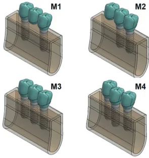
Four 3D models were used to simulate a posterior mandible bone block: two implants and fixed dental prosthesis (FDP) with a pontic in the center (model M1), two implants and FDP with a cantilever pontic at distal end (model M2), FDP supported by three implants with straight line arrangement (model M3), and FDP supported by three implants with staggered implant configuration (model M4) (Fig. 2).
Elastic modulus and Poisson’s ratio of the Y-TZP zirconia and bone were quoted in previous studies.
2,8Material properties of titanium are obtained from the material database of Solidworks (Dassault Sys- tems, SolidWorks Corporation). Material properties used in this study are listed in Table 1. All materials were assumed to be linear, elastic, homogeneous, and isotropic. Three-dimensional solid model of M1 has meshed with a tetrahedral solid element (30,539 elements and 47,473 nodes). In order to prevent displacement of the rigid body, fixed boundary conditions of 0-displacement and 0-rotation in all directions (X, Y, and Z) were assigned to the lower mandibular node. We did not allow mesial or distal deformation by assigning 0-displacement boundary conditions to nodes in mesial and distal surfaces of the mandible in the X direction. Contact interfaces between components of the implant were given sliding contact conditions by friction. The friction coefficient of the contact interface between the abut- ment lower part and the upper part of the fixture and that of the contact interface between the screw and the fixture were set to 0.05. In this condition, the
Table 1. Materials used in models of fixed dental restora- tion supported by implant and alveolar bone
Young’s modulus Poison’s ratio Y-TZP zirconia 2.10E + 11 Pa 0.32 Ti-6Al-4V 1.05E + 11 Pa 0.31 cp Ti grade 4 1.05E + 11 Pa 0.37 Cortical bone 1.00E + 10 Pa 0.30 Cancellous bone 1.37E + 09 Pa 0.30 Fig. 1. The M1 model reproduced all characteristics of implant-abutment-prosthesis components and mandibular alveolar bone. Model has meshed with tetrahedral elements. All nodes on the lower surface of the tooth were constrained in all directions (X, Y, and Z), as a boundary condition. Static axial (L1) and 45
olingual directed oblique (L2) force of 120 Newton was applied to the tooth at occlusal contact points respectively.
Fig. 2. M1, M2, M3, and M4 models of implant-supported
FDPs with various alignments and configurations.
contact area carried compressive and friction but not tension. All other contact surfaces of the implant components were considered to be bonded together.
Applied forces were 120 N axially (L1), or 120 N obliquely(L2) (Fig. 1).
Maximum von Mises and principal stresses on the fixture, abutment, screws, fixed prosthesis, and sup- porting alveolar bone were calculated and analyzed.
Results
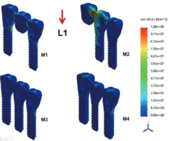
Peak von Mises stresses produced by oblique oc- clusal force were 3.4 - 5.1 times greater in implant and 3.5 - 8.3 times higher in alveolar bone than those produced by axial occlusal force. In the cantilever design of model M2, maximum stress values in the fixed prosthesis caused by vertical and oblique forces were 738.3 and 751.6 MPa, respectively, which were 4.4 and 1.5 times higher than those of model M1, re- spectively. Stress concentration was observed around the connector region between cantilever pontic and crown. When vertical load was applied, the maximum von Mises stress value in model M4 was 14.7 MPa at the bone. At all parts of the implant, prosthesis, and
bone, maximum von Mises stress values in model M4 were lower than those in M1 and M2 models. Stress concentration pattern demonstrated that von Mises stress was maximal around the outer surface of the abutment and a contact interface between abutment and screw. In components of implant, when the maximum stress value generated by oblique force in model M1 was converted to 100%, it increased to 122% in M2, but decreased to 71% and 69% in M3 and M4, respectively (Table 2, Fig. 3, 4).
In the supporting bone, if the magnitude of prin- cipal stress value generated by the oblique load in model M1 was converted to 100%, it increased to 106% in M2, but decreased to 74% and 66% in M3 and M4, respectively. The stress was the highest in the cortical bone at the neck of the implant but the lowest in the cancellous bone. Stress distribution of maximum principal stresses suggested that overload- ing of the cancellous bone might occur in tension and compression due to the lateral components of an occlusal force. However, a relatively small magni- tude of compressive stress was produced at cortical and cancellous bone by vertical loading (Figs 5 and 6).
Fig. 3. Maximum von Mises stresses generated in the implant fixture, screw, and abutment of hex external butt connection type by L1 load. Note the peak von Mises stress at the connector region of the cantilever pontic (M2).
Fig. 4. Maximum von Mises stresses generated in the implant fixture, screw, and abutment by L2 load. Note the peak von Mises stress at the abutment screw by L2.
Stress concentration area in the implant was observed
at the outer surface of the abutment and a contact
interface between abutment and screw.
Discussion
Loosening and fracture of the implant-supported prosthesis are usually associated with overloading on components, especially lateral loading. Peak von Mises stresses produced by oblique occlusal force were 3.4 - 5.1 times greater in implant and 3.5 - 8.3 times higher in alveolar bone than those produced by axial occlusal force. Oblique load increased stress on implants, prosthesis, and bone tissue in our study.
This is consistent with findings of recent studies
5,9showing increased stress in implant and supporting
bone under oblique loads. The general concept of ideal occlusion, which requires the application of biting force in the long axis of the tooth, was also confirmed by finite element analysis of implant- supported fixed prostheses in this study.
There have been many conflicting claims and re- search reports
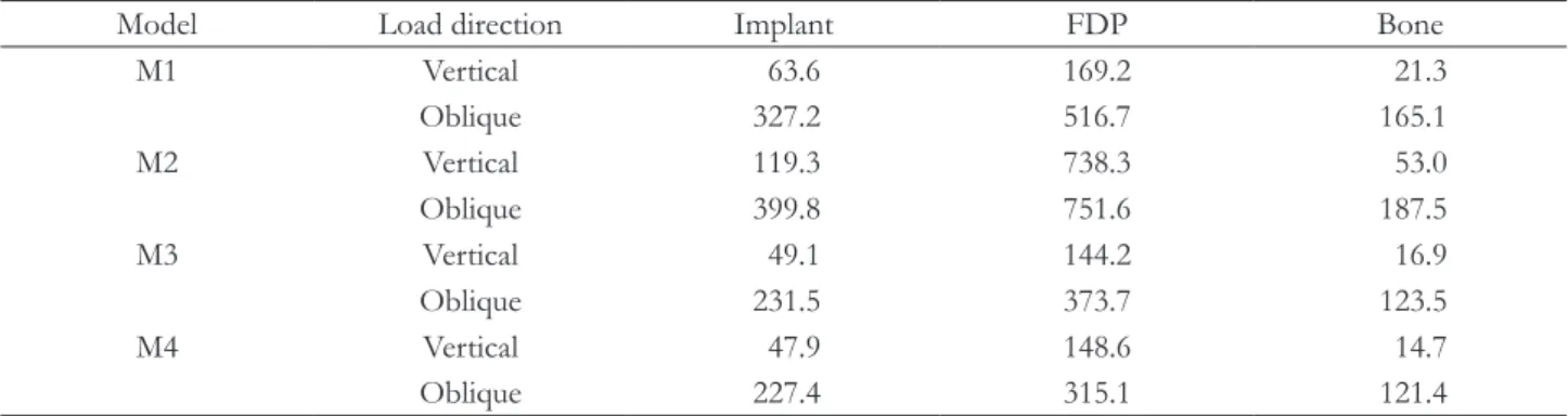
2-4,10on biomechanical implications of staggering implant arrangement. Only one offset distance from the straight alignment (1.8 mm) was analyzed in the present study. When oblique occlusal force was applied, offset arranfement of model M4 generated 227.4, 315.1 and 121.4 MPa maximum Table 2. Maximum von Mises stresses generated in implant, FDP and supporting bone by vertical and oblique loadings
Model Load direction Implant FDP Bone
M1 Vertical 63.6 169.2 21.3
Oblique 327.2 516.7 165.1
M2 Vertical 119.3 738.3 53.0
Oblique 399.8 751.6 187.5
M3 Vertical 49.1 144.2 16.9
Oblique 231.5 373.7 123.5
M4 Vertical 47.9 148.6 14.7
Oblique 227.4 315.1 121.4
Unit: MPa.
Fig. 6. Model M2 shows the highest principal stress value, while model M4 shows the lowest stress value.
Difference in the stress values between the M3 and M4 models was negligible. However, difference between stress values due to vertical load and lateral load was prominent.
(MPa) 300 200 100 0 -100 -200
-300 Tensile stress Compressive stress
L1-vertical load L2-oblique load
Principal stresses in the supporting bone
Fig. 5. The magnitude of maximum principal stresses generated in the supporting bone is shown in various colors. The blue color indicates where the compressive force has occurred, and the red color indicates where the tensile force has occurred.
Maximum Principal Stresses
Vertical (L1) Oblique (L2)
von Mises stresses in implant, prosthesis and alveolar bone, respectively, which were almost same as those of straight arrangement of model M3 (Table 2). The effect of staggering alignment on implant stress was negligible when compare to the effect of load direc- tion. Sato et al.
3suggested that offset implants were loaded with 59 - 65% compared to controls from geometric analysis. In 1997, Langert et al.,
10based on theoretical assumptions, proposed the biomechani- cal benefit of staggered placement to reduce stresses of implant. The previous literature’s
3,10assumption, which were not performed the laboratory analysis, that offset implant configuration is advantageous, was not validated by the results of this finite element analysis. Our results were consistent with the other FEA results of Huang et al.,
4who demonstrate the maximum stress in the alveolar bone around each im- plant did not show a difference between the straight- line and offset implant configurations. According to our research results, placing the multiple implants along the line of the dental arch is more advanta- geous than the staggered placement of the implant, considering the esthetic and oral hygiene care aspects.
The maximum stress generated by the M1 model, which was supported by two implants was 152%
higher than the M4 model, which was supported by three implants. The difference in maximum stress generated by the alignment of the implant placement (between M3 and M4) was negligible. The number of implants installed (between M1 and M4) had a greater impact than implant alignment (Table 2, Fig.
5).
Many systematic reviews
11,12have shown that short span FDPs with cantilever extensions represent a predictable treatment. Results of the present study showed that the cantilever design associated with implant support FDP slightly increased the stress in the alveolar bone. However, by showing a high stress concentration in the connector part of the FPD, fracture of the FPD may occur (Fig. 4, 5). The load should be avoided on cantilever portion to decrease the risk of fracture.
Results of the present study confirmed that the risk of bone overload essentially affected regions around the implant neck. Clinically, it has been reported that
loss of marginal bone mainly starts around the im- plant neck and progresses to the deep bone at a later stage (Fig. 5).
6Finite element analysis is based on mathematical calculations. Living tissues are beyond confines of set parameters and values since biology is not a comput- able entity.
9Therefore, finite element analysis should not be considered as the only means to understand the behavior of geometric structures in a given value.
Clinical trials should be performed after finite ele- ment analysis for final validation with biological sys- tems.
Conclusion
Peak von Mises stresses observed in implants pro- duced by oblique occlusal force were 3.4 - 5.1 times higher in implant and 3.5 - 8.3 times higher in alveo- lar bone than such stresses produced by axial occlusal force.
When the peak von Mises stress value of the im- plant generated by oblique force in model M1 was converted to 100%, it increased to 122% in M2, but decreased to 71% and 69% in M3 and M4, respec- tively.
In the supporting bone, when the maximum value of principal stress produced by oblique force in model M1 was converted to 100%, it increased to 106% in M2, but decreased to 74% and 66% in M3 and M4, respectively.
The effect of staggering alignment on implant stress was negligible. However, the number of im- plants installed had a more significant impact on stress.
ORCID
Hyunju Chung https://orcid.org/0000-0001-8461-5093
Chan Park https://orcid.org/0000-0001-5729-5127
Kwi-Dug Yun https://orcid.org/0000-0002-2965-3967
Hyun-Pil Lim https://orcid.org/0000-0001-5586-1404
Sang-Won Park https://orcid.org/0000-0002-9376-9104
Hongso Yang https://orcid.org/0000-0002-9138-4817
References
1. Liao S, Zhu X, Xie J, Sohodeb VK, Ding X. Influ- ence of trabecular bone on peri-implant stress and strain based on micro-CT finite element modeling of beagle dog. Biomed Res Int 2016;2016:3926941.
2. de Souza Batista VE, Verri FR, de Faria Almeida DA, Santiago Jr JF, Lemos CAA, Pellizzer EP. Eval- uation of the effect of an offset implant configura- tion in the posterior maxilla with external hexagon implant platform: A 3-dimensional finite element analysis. J Prosthet Dent 2017;118:363-71.
3. Sato Y, Uchida K, Okuyama T, Kitagawa N.
Verification of the influence of the arrangement of implants on the load distribution (a well-known figure by Rangert). J Oral Rehabil 2012;39:446-9.
4. Huang HL, Lin CL, Ko CC, Chang CH, Hsu JT, Huang JS. Stress analysis of implant-supported partial prostheses in anisotropic mandibular bone:
in-line versus offset placements of implant. J Oral Rehabil 2006;33:501-8.
5. Alencar SMM, Nogueira LBLV, de Moura WL, Rubo JH, de Oliveira Silva TS, Martins GAS, Moura CDVS. FEA of peri-implant stresses in fixed partial denture prostheses with cantilevers. J Prosthodont 2017;26:150-5.
6. Misch CE, Suzuki JB, Misch-Dietsh FM, Bidez MW.
A positive correlation between occlusal trauma and peri-implant bone loss: Literature support. Implant Dent 2005;14:108-16.
7. Sertgöz A, Güvener S. Finite element analysis of the effect of cantilever and implant length on stress distribution in an implant-supported fixed prosthe- sis. J Prosthet Dent 1996;76:165-9.
8. Anami LC, da Costa Lima JM, Corazza PH, Ya- mamoto ETC, Bottino MA, Borges ALS. Finite element analysis of the influence of geometry and design of zirconia crowns on stress distribution. J Prosthodont 2015;24:146-51.
9. Merdji A, Bouiadjra BB, Achour T, Serier B, Chikh BO, Feng ZO. Stress analysis in dental prosthesis.
Comput Mater Sci 2010;49:126-33.
10. Rangert BR, Sullivan RM, Jemt TM. Load fac- tor control for implants in the posterior partially edentulous segment. Int J Oral Maxillofac Implants
1997;12:360-70.
11. Storelli S, del Fabbro M, Scanferla M, Palandrani G, Romeo E. Implant supported cantilevered fixed dental rehabilitations in partially edentulous pa- tients: Systematic review of the literature. Part I.
Clin Oral Impl Res 2018;29 Suppl 18:253-74.
12. Wennström J, Zurdo J, Karlsson S, Ekestubbe
A, Gröndahl K, Lindhe J. Bone level change at
implant-supported fixed partial dentures with and
without cantilever extension after 5 years in func-
tion. J Clin Periodontol 2004;31:1077-83.
*교신저자: 양홍서
(61186)광주광역시 북구 용봉로 33, 전남대학교 치과대학 보철학교실 Tel: 062-530-5822|Fax: 062-530-0130|E-mail: [email protected] 접수일: 2020년 7월 1일|수정일: 2020년 7월 8일|채택일: 2020년 7월 25일
임플란트 배열과 하중 방향이 임플란트와 치조골에 미치는 유한요소 응력분석
정현주
1교수 , 박찬
2교수 , 윤귀덕
2교수 , 임현필
2교수 , 박상원
2교수 , 양홍서
2* 교수
1