Three-dimensional finite element analysis of implant-supported crown in fibula bone model
Young-Seok Park1, DDS, MS, PhD, Ho-Beom Kwon2*, DDS, MS, PhD
1Department of Oral Anatomy and Dental Research Institute, 2Department of Prosthodontics and Dental Research Institute, School of Dentistry, Seoul National University, Seoul, Republic of Korea
PURPOSE. The purpose of this study was to compare stress distributions of implant-supported crown placed in fibula bone model with those in intact mandible model using three-dimensional finite element analysis.
MATERIALS AND METHODS. Two three-dimensional finite element models were created to analyze biomechanical behaviors of implant-supported crowns placed in intact mandible and fibula model. The finite element models were generated from patient’s computed tomography data. The model for grafted fibula was composed of fibula block, dental implant system, and implant-supported crown. In the mandible model, same components with identical geometries with the fibula model were used except that the mandible replaced the fibula. Vertical and oblique loadings were applied on the crowns. The highest von Mises stresses were investigated and stress distributions of the two models were analyzed. RESULTS. Overall stress distributions in the two models were similar. The highest von Mises stress values were higher in the mandible model than in the fibula model. In the individual prosthodontic components there was no prominent difference between models.
The stress concentrations occurred in cortical bones in both models and the effect of bicortical anchorage could be found in the fibula model. CONCLUSION. Using finite element analysis it was shown that the implant- supported crown placed in free fibula graft might function successfully in terms of biomechanical behavior.
[J Adv Prosthodont 2013;5:326-32]
KEY WORDS: Finite element analysis; Mandibular reconstruction; Hemimandibulectomy; Fibula
INTRODUCTION
When oral cancer involves tongue and floor of the mouth, surgical resection has been the choice of treatment.1 Surgical resections frequently involve mandible and this ablative surgery usually leads to impaired oral functions, as
structures related to oral functions can be damaged. Altered oral anatomy, unbalanced and impaired muscles, the limita- tion of jaw movement and the existence of scar tissues influence patients’ speech, swallowing and mastication function as well as esthetics.1 Although rehabilitation using surgical and prosthodontic methods has been improved, patients still seem to have postoperative difficulties in restoring oral function to presurgical level.2 Before intro- duction of free flap reconstruction after mandibulectomy, postoperative impairments of oral functions were worse, and subsequent prosthodontic treatments were very chal- lenging to prosthodontist because of the lack of bony foundation and deformation of supporting tissues.3
Recently free-flap reconstruction seems to be the best treatment option and become the standard of treatment after mandibulectomy.4,5 The fibula has been thought of to be reliable after mandibulectomy in terms of providing good functional and esthetic results.6-8 It was reported that it can provide large quantity of bone and good vasculariza- tion, has good quality bone, might be contoured into vari- ous shape, and can give excellent esthetic results.4,6,9
Corresponding author:
Ho-Beom Kwon
Department of Prosthodontics and Dental Research Institute, School of Dentistry, Seoul National University, 275-1, Yeongeon-dong, Jongno-gu, Seoul, 110-749, Republic of Korea
Tel. 82220723816: e-mail, [email protected]
Received April 19, 2013 / Last Revision August 3, 2013 / Accepted August 13, 2013
© 2013 The Korean Academy of Prosthodontics
This is an Open Access article distributed under the terms of the Creative Commons Attribution Non-Commercial License (http://creativecommons.
org/licenses/by-nc/3.0) which permits unrestricted non-commercial use, distribution, and reproduction in any medium, provided the original work is properly cited.
This study was supported by grant no. 04-2010-0043 from the SNUDH Research Fund.
reached a reasonable level, postoperative complications were greatly reduced, the quality of life has been improved.6,11
However, there are shortcomings for the treatment using free fibula graft and osseointegrated implant. Because dimension of fibula is usually smaller than the mandible, it is not possible to restore alveolar height using fibula.12 When the contralateral side of the mandible is intact, this problem is important. As a result, when dental implants were placed, undesirable implant-crown ratio could be found. Although techniques such as a double-barrel fibula graft or high position of fibula were suggested,13,14 the pos- sibility of unfavorable aspects in terms of biomechanics cannot always be ignored in patient’s mandibular recon- struction. Biomechanical analysis for the mandibular recon- struction is necessary because the evaluation on the quality and quantity of bone are important for proper function of osseointegrated implant,15 and complications including implant failure and component fracture can occur in both grafted bone and the intact mandible.16 Because geometry of the model as well as the property of the material is important in biomechanical behavior,17 biomechanical anal- ysis of the implant-supported crown in fibula which has different geometry from mandible, usually unfavorable spa- tial relation, would be meaningful.
Although there are several known biomechanical analy- sis methods, most of them are usually difficult to be per- formed in clinical situation because of the difficulty of application methods. Finite element analysis has been used in dentistry to evaluate implant designs and factors related to the success of implant.18 Finite element analysis has advantages in investigating complex structures such as den- tal implant or human maxillofacial area. There have been many biomechanical studies using finite element analysis on the osseointegratedimplant on the intact mandible.19-21 However, it is not easy to find the biomechanical study on dental implant in fibula, which has a different geometry from the intact mandible. The purpose of this study was to compare biomechanical behaviors of implant-supported crown placed in fibula bone model with the implant-sup- ported crown in intact mandible model using three-dimen- sional finite element analysis.
MATERIALS AND METHODS
Two three-dimensional finite element models were created to simulate implant-supported crowns placed in intact man- dible and grafted fibula. The geometries of mandible and fibula were obtained from the patient’s computed tomogra- phy (CT) data. The patient was 20 year old female and had undergone hemimandibulectomy and reconstruction with
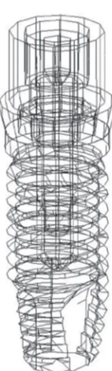
ated. For the finite element model of this study, segment of the fibula including mandibular first molar position was used. The length of the fibula segment used was 40 mm mesiodistally. Meshes of dental implant system with exter- nal hexagon (Osstem US system, Osstem Implant Co., Busan, Korea) were created and placed in the middle of bone model. The dimension of implant was 10 mm in length and 4 mm in diameter. All of the implant compo- nents including abutment and abutment screw were designed separately (Fig. 1). Some parts of the implant components including abutment screw were simplified for the reduction of calculation time. Crown meshes were cre- ated considering opposing maxillary dentition. The height of crown was about 14 mm. For the intact mandible model, normal mandible segment in the contralateral side with the same mesiodistaldimension was mirrored, was modified into edentulous mandible, and replaced the fibula bone model (Fig. 2). Except for bone meshes, meshes for other components were identical in both models. The total num- bers of nodes and finite elements were 39,365 and 118,594 respectively for the mandible model and 32,570 and 80,189 respectively for the fibula model.
Fig. 1. Implant components included in the models.
Implant, abutment, abutment screw meshes were generated separately.
In the two models, the implants were assumed to be attached to cancellous bones and cortical bones to simulate a complete osseointegration. In addition, abutment and crown were firmly attached to each other, and the thread portion of the abutment screw was attached to the screw hole of the implant fixture. Contact interfaces were set on the mating surfaces between the inferior surface of abut- ment and top of the fixture, and between the inferior sur- face of abutment screw head and abutment. The coefficient of friction values of 0.16 from the previous study was used for the contact between abutment and implant.22 For the contact between the abutment screw and abutment the fric- tion coefficient of 0.2 was used.22 The nodes in the medial and distal ends of the models were constrained in all direc- tions. Assumptions were made that all materials in the mod- els were homogenous, isotropic, and linearly elastic. The material properties of the elements were originated from the previous studies and are represented in Table 1.23,24
Based on the previous study, 50 N vertical force, 150 N vertical force and 50 N oblique force were used to simulate masticatory loading.25,26 Loads were evenly distributed on the buccal portion of the crown. Oblique loads were applied on the same area with vertical force and were at a 45 degrees angle to the long axis of the implant in bucco-
lingual direction. Comparisons of stress distributions were performed using measurements of the maximum von Mises stress values and analyzing contour plots of the von Mises stresses. The protocols and procedures of the study were reviewed and approved by the Institutional Review Board at the Seoul National University Dental Hospital.
RESULTS
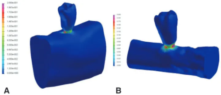
The highest stress concentrations were observed in the top of fixture and the inferior surface of abutment in all mod- els. However, positions of stress concentrations were dif- ferent based on the models. In the mandible model, highest stress concentrations occurred in the distolingual area on the top of the fixture. In contrast, in the fibula model, the high stress concentrations were located in the buccal and mesial area of the top of the fixture (Fig. 3). In case of oblique load, overall stress distributions were similar in the two models, however, they were different from those with vertical loadings.
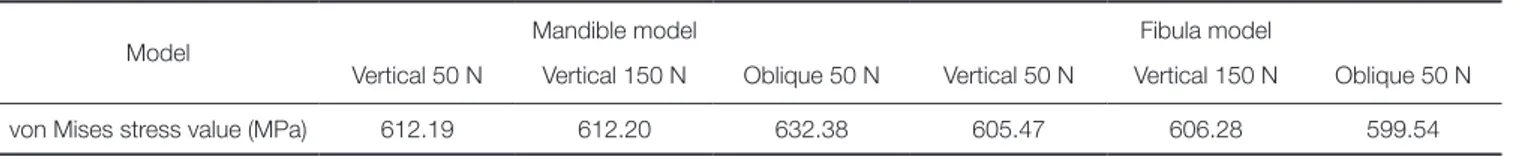
In all models, the highest von Mises stress value was found in the implant body. With vertical loads of 50 N, the highest von Mises stress values in the intact mandible mod- els was 612.19 MPa. It was higher than in the fibula model (605.47 MPa). With vertical loads of 150 N, the highest von Mises stress value of the mandible model (612.20 MPa) was higher than that in the fibula model (606.28 MPa). With oblique loading, the highest von Mises stress values were higher than that with vertical loadings, and the same ten- dency of higher stresses in mandible model was observed (Table 2).
In the individual prosthodontic components there was no prominent difference between models. The highest von Mises stress value of the abutment in the fibula model was similar to that in the mandible model (Table 3). Fig. 4 describes stress distributions of the implant components in the models with vertical force of 150 N.
In the bone, the highest von Mises stress values were much higher in the cortical bone than in the cancellous Fig. 2. Structures of the three-dimensional finite element
models. (A) Finite element model of the implant- supported crown placed in mandible model, (B) Finite element model of the implant-supported crown placed in fibula model.
A B
Table 1. Material properties used for the finite element models
Material Modulus of elasticity
(GPa) Poisson’s ratio
Titanium alloy 103.4 0.35
Gold alloy 91 0.33
Cortical bone 13.7 0.3
Cancellous bone (mandible) 1.37 0.3
Cancellous bone (fibula) 0.7 0.3
Fig. 3. The von Mises stress (GPa) distributions in the finite element models. High concentrations were found in the surface between abutment and implant body. (A) stress distribution in the intact mandible model, (B) stress distribution in the fibula model.
A B
bone. In the cancellous bone, all models showed similar val- ues (Table 4). In the cortical bone, the highest von Mises stress values in the fibula model was lower than that in the intact mandible model with vertical loading, and the increase of load intensity from 50 N to 150 N did not pro- duce noticeable difference. With oblique loading the high- est von Mises values were similar in the two models. In the bone, overall stress distributions in two modes were similar and the change of loading condition influenced the stress distribution on the cortical bone layer (Fig. 5). In the fibula bone model, the effect of bicortical anchorage could be found (Fig. 5).
The maximum displacement values of the models are shown in Table 5. The highest displacement value was obtained in the mandible model with oblique loading. The maximum displacements in all models were found in the interface between fixture and cortical bone.
Table 3. The highest von Mises stress values in the prosthodontic components
Model Mandible model Fibula model
Vertical 50 N Vertical 150 N Oblique 50 N Vertical 50 N Vertical 150 N Oblique 50 N von Mises stress
value (MPa)
Abutment 567.16 567.12 579.60 528.56 529.94 543.23
Abutment screw 48.47 48.51 39.54 68.86 70.99 73.19
Table 4. The highest von Mises stress values in the bone
Model Mandible model Fibula model
Vertical 50 N Vertical 150 N Oblique 50 N Vertical 50 N Vertical 150 N Oblique 50 N von Mises stress
value (MPa)
Cancellous bone 0.99 1.00 0.95 0.99 1.00 0.96
Cortical bone 92.17 92.08 96.33 88.72 89.62 96.82
Table 5. The maximum displacement values in the models
Model Mandible model Fibula model
Vertical 50 N Vertical 150 N Oblique 50 N Vertical 50 N Vertical 150 N Oblique 50 N
Displacement (mm) 0.0881 0.0881 0.0891 0.0453 0.0494 0.0563
Fig. 4. Stress distributions in implant components with 150 N vertical loading. von Mises stress (GPa)
distributions were different based on the models,
however, their values were similar. (A) stress distributions in implant components of mandible model, (B) stress distributions in implant components of fibula model.
A B
DISCUSSION
In this study it has been shown that the fibula bone graft might not be disadvantageous for the rehabilitation using dental implant after hemimandibulectomy in terms of stress distribution. There was no prominent stress peak in the fibula bone model and stress concentration levels of the fibula model were similar to those in the mandible model. Although the von Mises stress contour of the implant components showed that the stress distribution of the two models were not identical, the stress distribution of the fibula was not unfavorable. This result was in accor- dance with clinical results using fibula graft and osseointe- grated implants. The implant survival rate after mandibular reconstruction is known to be high and reported to range from about 85% to 100%.27-30 These high survival rates showed that implants in fibula might be stabilized biome- chanically.
Because the geometries of the two models were identi- cal except for bone parts, the difference in geometries and material properties of the bones might play a role in the difference of stress distribution. In this study, Young’s modulus of the cancellous bone in fibula was lower than that of the mandible. However, the values of von Mises stresses in the cancellous bone were relatively small, and it seems that the influence of the cancellous bone was weak.
Thus, the differences in the results may originate from the difference in the cortical bone layers. The thick cortical lay- er of fibula is thought to be the cause of the favorable results in the fibula model. It was previously reported that the cortical bone thickness that supports the implant fixture is important factors in osseointegration including the initial stability of implant, because thick cortical bone can con- tribute to the fixation of implant.31 The fibula was reported to have a thick cortical bone about 3.5 mm.32 Although it was reported in the same study that the fibula had lowest bone density among possible donor bones after maxillofa- cial resective surgery, the fibula was also reported to have relatively high bone-implant interfacedensity.32 In another studies the importance of cortical bone thickness was stressed. It was stated that implant is supported by cortical bone in terms of biomechanical view16 and bone quality and quantity could influence on the stress of osseointegrat- ed implants. 33,34 On the reason how thick cortical bone is advantageous in the initial stabilization of the implant, it was explained that thick cortical bone could reduce micro- movements of the implant, and during functional period of implant, better stress distributions can be maintained.35-37 In another study it was stated that the presence of dense bone is the prerequisites for predictable osseointegration.38 In a study using finite element analysis it was shown that maxi- mum stresses occurred in the cortical bone and thicker cor- Fig. 5. Stress distributions in cancellous and cortical bones. In the fibula model, the effect of bicortical anchorage can be found. (A) stress distributions in the bone of the mandible model with 50 N of vertical loading, (B) stress distributions in the bone of the mandible model with 150 N of vertical loading, (C) stress distributions in the bone of the mandible model with 50 N of oblique loading, (D) stress distributions in the bone of the fibula model with 50 N of vertical loading, (E) stress distributions in the bone of the fibula model with 150 N of vertical loading, (F) stress distributions in the bone of the fibula model with 50 N of oblique loading.
A B C
D E F
In addition to the thickness of cortical bone, bicortical anchorage can be a factor to explain the favorable results in the fibula model. In this study the fibula model showed that the stress concentration occurred in lower cortical layer of the fibula. This result is in accordance with the previous reports. In a previous study using finite element analysis bicortical anchorage reduced the peak stress in cortical and cancellous bone.40 In another study measured the removal torque it was reported that the removal torque was higher for the bicortical implants than for the monocortical ones.
In a study using finite element analysis bicortical anchorage was reported to improve initial stability of the implant.41 In this study bicortical anchorage of the implant in the fibula model was thought to contribute to the favorable results.
However, it was stated that bicortical anchorage might not be related with the reduction of the risk of marginal bone loss because it has little influence on the displacement of coronal part of the implant.42 Although the maximum dis- placement in the fibula model was smaller than in the man- dible model in this study, further study is required to evalu- ate the contribution of bicortical anchorage on the margin- al bone loss. Quantitative considerations on factors includ- ing dynamic nature of masticatory force, the influence of implant-crown ratio,the limitation of mandibular motion, muscular imbalance, and quantity of offset load from unfa- vorable maxillomandibular relationship are required in mandibular reconstruction patients. In this study to analyze the difference of the mandible and the fibula, same compo- nents were used except for the bone meshes. Although patients’ original vertical dimensions can be reduced inten- tionally with the limited mouth opening and for more favorable biomechanical results, crown length of the implant-supported prosthesis in the fibula is usually longer than that in the mandible and this might produce unfavor- able biomechanical situation. Further quantitative studies are required for analyzing the effect of the various crown length of the implant-supported prosthesis in the fibula graft model.
In the present study contact condition was included between abutment and fixture, and abutment screw and abutment for the more precise prediction of models. This setting of contact condition seemed to contribute to the production of precise results. Although finite element anal- ysis is a method for obtaining a solution by dividing objects into a small elements and it is the most suitable to oral and maxillofacial area which has highly complex geometries, many simplifications and assumptions in terms of detailed geometry, material properties, boundary conditions, and the interface between the bone and implant are included in finite element analysis.18 In future studies using finite ele-
In this study using finite element analysis the stress distri- butions in the fibula models were comparable to those in the mandible model. The osseointegrated implants used with the fibula free flap reconstruction might be expected to have predictable biomechanical behavior in their function.
REFERENCES
1. Beumer J III, Marunick MT, Esposito SJ. Maxillofacial Rehabilitation: Surgical and Prosthodontic Management of Cancer-Related Acquired, and Congenital Defects of the Head and Neck. 1st ed. Chicago; Quintessence Publishing Co, Inc.; 2011. p. 61-154.
2. Olson ML, Shedd DP. Disability and rehabilitation in head and neck cancer patients after treatment. Head Neck Surg 1978;1:52-8.
3. Komisar A. The functional result of mandibular reconstruc- tion. Laryngoscope 1990;100:364-74.
4. Hidalgo DA. Fibula free flap: a new method of mandible re- construction. Plast Reconstr Surg 1989;84:71-9.
5. Ferrari S, Bianchi B, Savi A, Poli T, Multinu A, Balestreri A, Ferri A. Fibula free flap with endosseous implants for recon- structing a resected mandible in bisphosphonate osteonecro- sis. J Oral Maxillofac Surg 2008;66:999-1003.
6. Zlotolow IM, Huryn JM, Piro JD, Lenchewski E, Hidalgo DA. Osseointegrated implants and functional prosthetic re- habilitation in microvascular fibula free flap reconstructed mandibles. Am J Surg 1992;164:677-81.
7. Hayter JP, Cawood JI. Oral rehabilitation with endosteal im- plants and free flaps. Int J Oral Maxillofac Surg 1996;25:3-12.
8. Lukash FN, Sachs SA, Fischman B, Attie JN. Osseointe- grated denture in a vascularized bone transfer: functional jaw reconstruction. Ann Plast Surg 1987;19:538-44.
9. Hidalgo DA. Aesthetic improvements in free-flap mandible reconstruction. Plast Reconstr Surg 1991;88:574-85.
10. Gürlek A, Miller MJ, Jacob RF, Lively JA, Schusterman MA.
Functional results of dental restoration with osseointegrated implants after mandible reconstruction. Plast Reconstr Surg 1998;101:650-5.
11. Urken ML, Buchbinder D, Weinberg H, Vickery C, Sheiner A, Parker R, Schaefer J, Som P, Shapiro A, Lawson W, et al.
Functional evaluation following microvascular oromandibular reconstruction of the oral cancer patient: a comparative study of reconstructed and nonreconstructed patients. Laryngo- scope 1991;101:935-50.
12. Frodel JL Jr, Funk GF, Capper DT, Fridrich KL, Blumer JR, Haller JR, Hoffman HT. Osseointegrated implants: a com- parative study of bone thickness in four vascularized bone flaps. Plast Reconstr Surg 1993;92:449-55.
13. Horiuchi K, Hattori A, Inada I, Kamibayashi T, Sugimura M,
Yajima H, Tamai S. Mandibular reconstruction using the dou- ble barrel fibular graft. Microsurgery 1995;16:450-4.
14. Chang YM, Santamaria E, Wei FC, Chen HC, Chan CP, Shen YF, Hou SP. Primary insertion of osseointegrated dental im- plants into fibula osteoseptocutaneous free flap for mandible reconstruction. Plast Reconstr Surg 1998;102:680-8.
15. Marunick MT, Roumanas ED. Functional criteria for man- dibular implant placement post resection and reconstruction for cancer. J Prosthet Dent 1999;82:107-13.
16. Esposito M, Hirsch JM, Lekholm U, Thomsen P. Biological factors contributing to failures of osseointegrated oral im- plants. (II). Etiopathogenesis. Eur J Oral Sci 1998;106:721- 64.
17. van Eijden TM. Biomechanics of the mandible. Crit Rev Oral Biol Med 2000;11:123-36.
18. Geng JP, Tan KB, Liu GR. Application of finite element analysis in implant dentistry: a review of the literature. J Prosthet Dent 2001;85:585-98.
19. Meijer HJ, Kuiper JH, Starmans FJ, Bosman F. Stress distri- bution around dental implants: influence of superstructure, length of implants, and height of mandible. J Prosthet Dent 1992;68:96-102.
20. Baggi L, Pastore S, Di Girolamo M, Vairo G. Implant-bone load transfer mechanisms in complete-arch prostheses sup- ported by four implants: a three-dimensional finite element approach. J Prosthet Dent 2013;109:9-21.
21. de Paula GA, da Mota AS, Moreira AN, de Magahlães CS, Cornacchia TP, Cimini CA Jr. The effect of prosthesis length and implant diameter on the stress distribution in tooth-im- plant-supported prostheses: a finite element analysis. Int J Oral Maxillofac Implants 2012;27:e19-28.
22. Wang RF, Kang B, Lang LA, Razzoog ME. The dynamic na- tures of implant loading. J Prosthet Dent 2009;101:359-71.
23. Wu JC, Chen CS, Yip SW, Hsu ML. Stress distribution and micromotion analyses of immediately loaded implants of varying lengths in the mandible and fibular bone grafts: a three-dimensional finite element analysis. Int J Oral Maxillofac Implants 2012;27:e77-84.
24. Rho JY, Ashman RB, Turner CH. Young’s modulus of tra- becular and cortical bone material: ultrasonic and microten- sile measurements. J Biomech 1993;26:111-9.
25. Haraldson T, Carlsson GE. Bite force and oral function in patients with osseointegrated oral implants. Scand J Dent Res 1977;85:200-8.
26. Liao SH, Tong RF, Dong JX. Anisotropic finite element modeling for patient-specific mandible. Comput Methods Programs Biomed 2007;88:197-209.
27. Peled M, El-Naaj IA, Lipin Y, Ardekian L. The use of free fibular flap for functional mandibular reconstruction. J Oral Maxillofac Surg 2005;63:220-4.
28. Hidalgo DA, Rekow A. A review of 60 consecutive fibula free flap mandible reconstructions. Plast Reconstr Surg 1995;
96:585-96.
29. Sieg P, Zieron JO, Bierwolf S, Hakim SG. Defect-related vari- ations in mandibular reconstruction using fibula grafts. A re- view of 96 cases. Br J Oral Maxillofac Surg 2002;40:322-9.
30. Smolka K, Kraehenbuehl M, Eggensperger N, Hallermann
W, Thoren H, Iizuka T, Smolka W. Fibula free flap recon- struction of the mandible in cancer patients: evaluation of a combined surgical and prosthodontic treatment concept.
Oral Oncol 2008;44:571-81.
31. Kido H, Schulz EE, Kumar A, Lozada J, Saha S. Implant di- ameter and bone density: effect on initial stability and pull- out resistance. J Oral Implantol 1997;23:163-9.
32. Myoung H, Kim YY, Heo MS, Lee SS, Choi SC, Kim MJ.
Comparative radiologic study of bone density and cortical thickness of donor bone used in mandibular reconstruction.
Oral Surg Oral Med Oral Pathol Oral Radiol Endod 2001;
92:23-9.
33. van Staden RC, Guan H, Loo YC. Application of the finite element method in dental implant research. Comput Methods Biomech Biomed Engin 2006;9:257-70.
34. Chou HY, Müftü S, Bozkaya D. Combined effects of implant insertion depth and alveolar bone quality on periimplant bone strain induced by a wide-diameter, short implant and a narrow-diameter, long implant. J Prosthet Dent 2010;104:
293-300.
35. Holmes DC, Loftus JT. Influence of bone quality on stress distribution for endosseous implants. J Oral Implantol 1997;
23:104-11.
36. Brunski JB. Biomechanical factors affecting the bone-dental implant interface. Clin Mater 1992;10:153-201.
37. Ichikawa T, Kanitani H, Wigianto R, Kawamoto N, Matsumoto N. Influence of bone quality on the stress distri- bution. An in vitro experiment. Clin Oral Implants Res 1997;
8:18-22.
38. Clelland NL, Lee JK, Bimbenet OC, Gilat A. Use of an axi- symmetric finite element method to compare maxillary bone variables for a loaded implant. J Prosthodont 1993;2:183-9.
39. Truhlar RS, Orenstein IH, Morris HF, Ochi S. Distribution of bone quality in patients receiving endosseous dental im- plants. J Oral Maxillofac Surg 1997;55:38-45.
40. Huang HL, Fuh LJ, Ko CC, Hsu JT, Chen CC. Biomechanical effects of a maxillary implant in the augmented sinus: a three-dimensional finite element analysis. Int J Oral Maxillofac Implants 2009;24:455-62.
41. Demenko V, Linetskiy I, Nesvit K, Shevchenko A. Ultimate masticatory force as a criterion in implant selection. J Dent Res 2011;90:1211-5.
42. van Oosterwyck H, Duyck J, van der Sloten J, van der Perre G, De Cooman M, Lievens S, Puers R, Naert I. The influence of bone mechanical properties and implant fixation upon bone loading around oral implants. Clin Oral Implants Res 1998;9:407-18.