이남기*∙백승학***∙최동순*∙박영욱**∙김지혁**∙차봉근*
강릉대학교 치과대학 *교정학교실, **구강악안면외과학교실
***서울대학교 치의학전문대학원 교정학교실
악정형력 적용을 위한 골내 고정원으로서 미니플레이트 형상의 영향: 3차원 유한요소법적 연구
INFLUENCE OF MINIPLATE SHAPES AS SKELETAL ANCHORAGE FOR APPLICATION OF ORTHOPEDIC FORCE:
A THREE-DIMENSIONAL FINITE ELEMENT ANALYSIS
Nam-Ki Lee * , Seung-Hak Baek *** , Dong-Soon Choi * , Young-Wook Park ** , Ji-Hyuck Kim ** , Bong-Kuen Cha *
*Department of Orthodontics, **Department of Oral and Maxillofacial Surgery, College of Dentistry, Kangnung National University
***Department of Orthodontics, School of Dentistry, Seoul National University, South Korea
Purpose: This study was performed to evaluate the stress distribution in the bone and the displacement distribution of the miniscrew under orthopedic force with two different types of miniplate design as skeletal anchorage for orthopedic treatment.
Materials and methods: Finite element models were made for 6-hole miniplate (0.8mm in thickness), which were designed in two different shapes-one is curvilinear shaped (C plate, Jeil Medical Co., Korea) and another, Y shaped (Y plate), fixed with 3 pieces of miniscrew 2mm-diameter and 6mm-long respec- tively. A traction force of 4 N was applied in 0�, 30�and 60�to imaginary axis connecting two unfixed dis- talmost holes of the miniplate.
Results: The maximum von Mises stress in the bone was much greater in the cortical portion rather than in the cancellous portion. C plate showed greater maximum von Mises stress in the cortical bone than Y plate. The maximum displacement of the miniscrew was greater in C plate than Y plate. The more increased the angle of the applied orthopedic force, the greater maximum von Mises stress in the bone and maximum displacement of the miniscrew. It was observed that in C plate, the von Mises stress in the bone and displacement of the miniscrew were distributed around the distalmost screw-fixed area.
Conclusions: The results suggest that Y plate should have the advantage over C plate and in the placement of the miniplate, its imaginary axis should be placed as parallel as possible to the direction of orthopedic force to obtain its primary stability.
Key words: Miniplate, Skeletal anchorage, Primary stability, Finite element analysis
Abstract
Ⅰ. 서 론
일반적인 교정력보다 큰 힘이 필요한 성장기 아동의 악정 형 치료에서는 골격적인 효과와 함께 많은 치아치조성 이동 이 보고되고 있다
1). 이를 보완하고 보다 순수한 골격적 효 과를 얻기 위해 골 고정원 (skeletal anchorage)이 널리 고 려될 수 있으며, 이미 치아 이동을 위한 교정치료에 골유착 임플란트
2-6), 미니스크류
7-10), 미니플레이트 시스템 (titani- um miniplate와 monocortical screws)
11,12)등이 사용되고 있다. 또한 최근에는 상악골 전방견인과 같은 악정형 치료 에서 골 고정원을 사용함으로써 치아의 고정원 소실을 최소 화 할 수 있다는 보고가 이루어지고 있다
13-15).
그러나 골유착 임플란트의 경우 식립 부위가 극히 제한적 인 점, 3~4개월간 골유착을 위해 기다려야 하는 점과 고가 의 치료비가 필요하다는 단점이 있으며, 최근에 많이 이용 되고 있는 미니스크류의 경우 성장기 아동에서의 높은 탈락 률이나 파절 및 치근 손상 유발
16)등을 고려할 때 악정형적인 목적으로 사용하기에 한계가 있다. 따라서 외과용 미니플레 이트 시스템은 치근과 멀리 떨어진 위치 즉 관골하능 (infrazygomatic crest)
11,12,15)이나 상악골의 외측 비벽 (lateral nasal walls of the maxilla)
17,18)에 식립되므로 치아의 후방이동이나 압하와 같은 이동이 용이하며, 상악골 전방견인 등과 같은 악정형 치료 시에도 골 고정원으로서 사용될 수 있다(Fig. 1). 하지만 미니플레이트의 위치 및 고
정(fixation)을 위해서 외과적 소수술이 필요하며
15), 간혹 미니플레이트의 동요도가 증가되는 경우 재수술이 필요해 통상의 미니스크류 단독의 재식립에 비해서는 좀 더 복잡하 다
19). 따라서 미니플레이트 시스템의 안정성(stability)이 가급적 치료 종료시까지 잘 유지되어야 하나 아직까지 여러 미니플레이트의 형상(shape)에 따른 유지력에 관한 연구는 미흡하다.
따라서 본 연구의 목적은 악안면 영역에서 악정형 치료를 위한 골내 고정원으로 사용 가능한 외과용 미니플레이트의 초기 안정성과 연관해 골내 응력 분포 양상과 미니스크류의 변위 정도를 분석하여 미니플레이트 시스템의 임상적용 시 도움이 되고자 시행하였다.
Ⅱ. 연구재료 및 방법
1. 유한요소 모델 제작
3차원 형상의 유한요소 모델은 SolidWorks 2006 CAD 프로그램 (Solidworks Co, Concord, USA)을 이용해 제 작하였고, 미니플레이트와 미니스크류는 제일 메디컬코퍼 레이션(Seoul, Korea)의 Le Forte system의 CAD (Computer Aided Design) 데이터를 참조하였다.
형상(shape)이 다른 2 종류의 미니플레이트에 적용되는 힘의 방향에 따른 미니플레이트의 초기 안정성을 살펴보고
Fig. 1. Anterior protraction of the maxilla with miniplate system as an intraoral anchor.
자, 골 모델은 최대한 단순화 하였으며 이를 위해 피질골의 두께 1mm, 해면골의 두께 17mm, 기저부 피질골의 두께 2mm인 25.0mm × 25.0mm × 20mm의 육면체 구조로 제작하였다. 단순화한 골 모델에 6 hole의 곡선형 미니플레 이트 (Curvilinear shaped miniplate, C plate, 두께 0.80mm, hole중심간 거리 5.50mm, Le Forte system, Jeil Medical Co, Seoul, Korea)와 Y자형 미니플레이트 (Y shaped miniplate, Y plate)를 각각 위치시키고, 이를 고정하기 위해 직경 2mm, 길이 6mm인 미니스크류 3개를 골 표면에 대해 90。로 식립한 2개의 모델을 제작하였다 (Fig. 2). 이 2개 모델의 평균 nodes 및 elements의 수는 89212 와 65642이었다.
2. 경계조건과 재료의 물성치 부여
경계조건은 피질골, 해면골과 기저부 피질골을 포함한 골 의 상부와 기저부 피질골에서 움직임이 발생하지 않도록 X, Y, Z축의 3 방향으로 모두 구속하였으며 미니플레이트, 미 니스크류와 골 간에는 노드면 접촉으로 설정하였다(Fig.
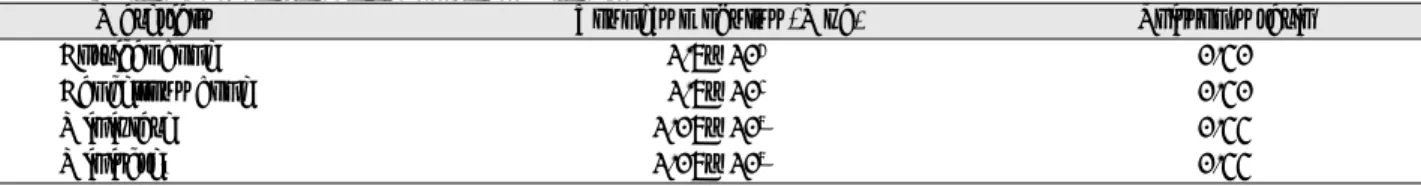
2). 모델의 단순화와 응력의 수치적 계산을 위해 모델의 물 리적 특성은 재료의 기계적 특성이 균일하다는 균질성, 구 조의 변형이나 변위는 적용된 힘에 비례하고 변위 정도에는 무관하다는 선형특성, 재료의 특성 및 역학적 거동이 X, Y, Z축 3방향으로 동일하다는 등방성을 갖는 것으로 가정하였 다. 재료의 물성치로 피질골 및 해면골, 미니플레이트와 미 니스크류의 탄성계수 (Young’s modulus)와 포와송의 비 Table 1. Profile of the miniplate systems used in this study
Models Diameter* (mm) Length* (mm) Number*
C plate 2 6 3
Y plate 2 6 3
C plate, Curvilinear shaped miniplate; Y plate, Y shaped miniplate
* the diameter, length and number of the used miniscrews
Table 2. Material properties of constituent materials
Materials Young's modulus (Mpa) Poisson's ratio
Cortical bone 1.5×10
40.30
Cancellous bone 1.5×10
30.30
Miniplate 1.05×10
50.33
Miniscrew 1.05×10
50.33
Fig. 2. Three-dimensional finite element models for the bone and the two types of miniplate systems (C plate, Y plate).
3. 힘의 적용과 응력 분석
2개의 모델에서 골 바깥쪽으로 나와 있는 미니플레이트의 2 hole을 연결한 선을 가상의 축으로 설정하고 이 축에 대 해 4N의 교정력을 0。, 30。, 60。방향으로 각각 적용하였다 (Fig. 2).
3차원 유한요소 해석 프로그램인 SolidWorks 2006 pro- gram (Solidworks Co, Concord, USA)를 이용하여 미니 플레이트 주변 피질골과 해면골의 최대 응력 (von Mises stress)을 살펴보았고, 미니플레이트를 고정한 미니스크류 의 초기 안정성을 간접적으로 살펴보고자 미니스크류의 변 위 (displacement)를 비교 분석하였다. 각 조건에 따른 최 대응력과 변위의 차이를 가시화하기 위해 적색에서 청색까 지의 색상으로 구분하여 표시하였다.
Ⅲ. 연구 성적
1. 피질골 내의 최대 응력 (Maximum von Mises Stress)
C plate의 경우 피질골 내에 작용하는 최대 응력값은 가 해 지 는 힘 의 방 향 이 0。, 30。, 60。에 따 라 각 각
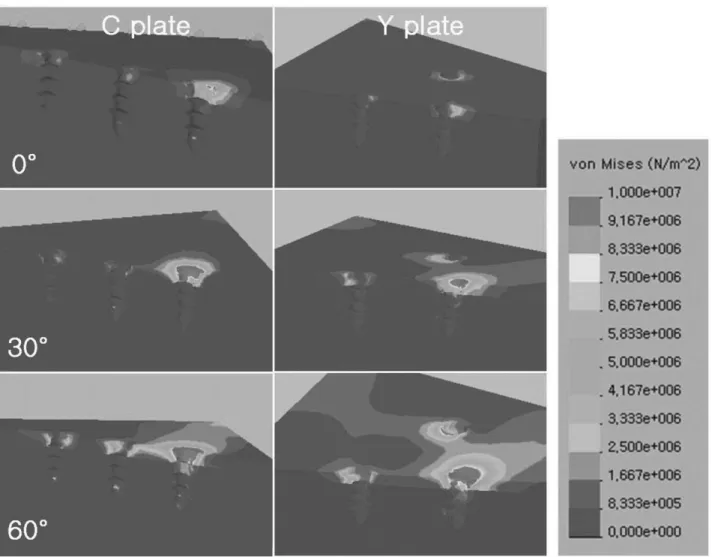
12.632MPa, 28.713MPa, 43.645MPa로 나타났으며, Y plate의 경우에는 각각 10.830MPa, 26.639MPa, 40.806MPa로 나타났다(Table 3). 즉 C plate와 Y plate 모두에서 피질골 내의 최대 응력은 힘의 방향이 증가할수록 증가되는 양상을 보였으며(Fig. 3), C plate의 경우가 Y plate보다 피질골 내의 최대 응력이 전반적으로 큰 양상을 보였다.
또한 C plate의 경우 피질골 내에 응력이 집중되는 부위 는 가장 원심측 미니스크류 고정 부위이었으나, Y plate의 경우에는 가장 원심측 미니스크류 고정 부위 이외의 부위로 분산되는 경향을 보였다(Fig. 3).
2. 해면골 내의 최대 응력
C plate의 경우 해면골 내에 작용하는 최대 응력값은 가 해지는 힘의 방향이 0。, 30。, 60。에 따라 각각 3.625 MPa, 4.596MPa, 7.004MPa로 나타났으며, Y plate의 경우에는 각각 1.645MPa, 4.483MPa, 6.752MPa로 나 타났다(Table 4, Fig. 3). 즉 C plate와 Y plate모두에서 해면골 내의 최대 응력은 힘의 방향이 증가할수록 증가되었 으며, C plate의 경우가 Y plate보다 미세하게 큰 양상을 보였다.
Table 3. Maximum von Mises stress (MPa) on the cortical bone of each model
Axis Maximum von Mises stress (Mpa)
C plate Y plate
0� 12.632 10.403
30� 28.713 26.639
60� 43.645 40.806
Table 4. Maximum von Mises stress (MPa) on the cancellous bone of each model
Axis Maximum von Mises stress (Mpa)
C plate Y plate
0� 3.625 1.645
30� 4.596 4.483
60� 7.004 6.752
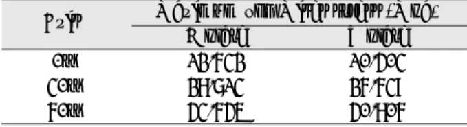
Table 5. Maximum values of displacement (㎛) for the cortical bone and miniscrew of each model
C plate Y plate
Axis Cortical bone Miniscrew *Relative Cortical bone Miniscrew Relative
dispacement dispacement
0� 1.542 2.939 1.397 1.261 1.656 0.395
30� 2.519 5.468 2.949 1.855 4.271 2.416
60� 3.309 7.896 4.587 2.279 6.671 4.392
*Relative displacements were calculated as differences between maximum displacements of cortical bone and miniscrew
elements.
전체적으로 해면골과 피질골내에서의 응력을 비교해 보 면, C plate와 Y plate 모두에서 피질골 내에서의 응력이 해면골 내에서의 응력보다 컸다.
3. 피질골과 미니스크류의 최대 변위 (Maximum Values of Displacement)
C plate의 경우 가해지는 힘의 방향 즉 0。, 30。, 60。에 따라 피질골의 최대 변위는 각각 1.542㎛, 2.519㎛, 3.309
㎛로, 미니스크류의 최대 변위는 2.939㎛, 5.468㎛, 7.896
㎛로 나타났으며, 피질골과 미니스크류 간의 상대적인 변위 는 1.397㎛, 2.949㎛, 4.587㎛로 나타났다. 또한 Y plate
의 경우에 피질골의 최대 변위는 각각 1.261㎛, 1.855㎛, 2.279㎛로, 미니스크류의 최대 변위는 1.656㎛, 4.271㎛, 6.671㎛로 나타났으며, 피질골과 미니스크류 간의 상대적 인 변위는 0.395㎛, 2.416㎛, 4.392㎛로 나타났다 (Table 5).
피질골과 미니스크류의 최대 변위는 힘의 방향에 관계없 이 C plate에서 Y plate보다 컸다. 미니스크류의 변위는 피 질골의 변위에 비해 컸으며, 특히 힘의 방향이 증가될수록 미니스크류의 최대 변위가 증가되었다.
또한 변위의 전체적인 분포 양상에서 C plate는 Y plate 에 비해 가장 원심측 미니스크류 고정 부위에 집중되었다 (Fig. 4).
Fig. 3. Von Mises stress distributions of the cortical and cancellous bone in C plate and Y plate models.
Ⅳ. 총괄 및 고찰
최근에 골격적 문제가 있는 성장기 아동의 악정형 치료를 위해 전통적인 치아 고정원 대신에 골내 고정원으로서 미니 플레이트 시스템을 이용해 보다 순수한 골격적 치료 효과를 얻기 위한 시도가 진행되고 있다
15,17,18).
외과용 미니플레이트는 골절 또는 악교정 수술시 분절된 골편을 견고하게 고정(rigid-fixation) 하기 위해 사용되어 왔으며, 이러한 고정법의 안정성
23-25)과 일정한 하중에서 골 편 고정에 이용된 다양한 미니플레이트와 스크류의 종류에 따라 골 내부와 고정 파트에서의 응력 분포 등에 대한 연구
등
22,26,27)도 보고되었다. 하지만 교정력 또는 악정형력 하에
서 골내 고정원으로 사용되는 미니플레이트처럼 한쪽만 고 정된 미니플레이트 즉, 캔티레버 로딩(cantilever loading) 하에서 미니플레이트의 초기 안정성에 대한 연구는 전무한
실정이다. 따라서 본 연구에서는 생체에서의 생역학적 연구 를 위해 널리 사용되는 방법인 유한요소분석을 이용하여
28,29)
, 미니플레이트의 형상에 따른 골 내의 응력분포와 미니
스크류의 변위 양상을 비교 분석함으로써, 골 고정원으로서 미니플레이트의 안정적 사용을 도모하여 성장기 아동의 악 정형 치료에 임상적 도움이 되고자 하였다.
본 연구에서는 미니플레이트가 식립되는 골 부위를 단순 화하여 응력 분포 양상을 관찰하였으며, 표층 피질골 두께 의 1mm 설정은 상악 소구치 치근부위와 관골하능 부위의 평균적인 피질골의 두께가 1.4mm 미만인 점을 반영하여 설정하였으나
30), 해면골의 두께는 미니스크류를 충분히 수 용하도록 설정하여 실제 해부학적 한계와는 차이가 있다.
미니플레이트의 형상이 다른 C plate와 Y plate에서 악
정형력(4N) 적용시 골에 가해지는 최대 응력 값을 비교한
결과 피질골과 해면골 모두에서 C plate가 Y plate에 비해
Fig. 4. Displacement distributions of the bone and miniscrew in C plate and Y plate models.
크게 나타났으며, 또한 악정형력의 방향이 증가할수록 응력 이 증가되었다. 전반적으로 피질골에서의 응력이 해면골에 서의 응력보다 대략 4~6배 정도 큰 양상을 보였다(Table 3, 4). 이 결과는 힘이 가해지는 방향으로 미니스크류 식립 부위의 피질골에 최대 응력이 집중됨을 보고한 임 등
31)과 변 등
32)과 Motoyoshi 등
33)의 연구와 유사한 결과를 보였다. 또 한 피질골 내에 응력이 집중되는 부위와 관련해, C plate의 경우에는 가장 원심측 미니스크류 고정 부위인 반면에, Y plate의 경우에는 가장 원심측 미니스크류 고정 부위 이외 의 부위로 힘이 분산되는 경향을 보였다(Fig. 3). 이는 C plate가 Y plate에 비해 미니플레이트의 고정되지 않은 가 장 원심측 2 hole을 연결하여 설정한 가상의 축에 대해 악 정형력의 방향이 벗어날수록 적용된 힘이 미니플레이트와 미니스크류를 통해 피질골에 골고루 분산되지 못하고 한 곳 으로 응력이 집중되어 골내 고정원으로서 불리함을 의미한 다. 이를 고려하여 임상 적용시 상악골 전방견인을 위한 미 니플레이트는 Y plate가 유리하며, 미니플레이트의 가상의 축이 일반적인 상악골 전방견인 방향 즉, 교합 평면에 대해 하방으로 30。방향에 일치되도록 미니플레이트를 식립하는 것이 골 내 응력이 최소화 된다는 점에서 유리할 것으로 사 료된다.
미니플레이트의 형상에 따른 피질골과 미니스크류에서의 최대 변위를 비교한 결과, C plate가 Y plate 에 비해 모두 에서 컸으며, 미니스크류와 피질골간의 최대 변위 차이인 상대적 변위(relative displacement) 또한 더 큰 양상을 보 였다. 또한 악정형력의 방향이 증가할수록 C plate가 Y plate 에 비해 미니스크류의 변위 및 상대적 변위가 증가되 는 양상을 보였으며(Table 5, Fig. 4), 특히 이러한 변위는 가장 원심측 미니스크류 고정 부위에서 발생되었다. 따라서 이 결과는 악정형력 조건하에서 미니플레이트의 형상에 따 라 미니플레이트를 고정하는 각각의 미니스크류에 힘이 골 고루 분산되지 못하고 힘 적용점에 가까운 미니스크류에서 최대 변위가 발생해 이로 인한 탈락 가능성이 높아져 미니 플레이트의 초기 안정성에 차이가 남을 보여준다. 따라서 최대 변위 측면에서도 상악골 전방견인을 위한 골내 고정원 으로 C plate에 비해 Y plate가 좀 더 유리하리라 사료 된다.
본 연구에서는 미니플레이트 형상을 미니스크류로 고정하 는데 골 표면을 단순화한 모델을 사용하였으므로 골 표면의 굴곡 정도나 상악동 등의 해부학적 부위 등이 고려되지 못 한 점과 생체 내에서 장기간에 걸친 미니스크류 주변 골에 서의 골 개조현상(bone remodeling) 등을 반영하지 못하 는 한계점이 있다. 따라서 실제 악안면 영역의 3차원 모델 을 이용한 생역학적 연구나 임상에서 장기간에 걸친 골개조
Ⅴ. 결 론
악정형력 적용을 위한 골내 고정원으로서 미니플레이트의 형상(shape)에 따른 응력 분포와 미니스크류의 변위 양상 을 3차원 유한요소 분석으로 비교한 결과 다음과 같은 결론 을 얻었다.
1. 골에 나타나는 최대 응력을 비교하면, 피질골 내에서의 응력이 해면골에 비해 4~6배 정도 컸으며, 전반적으 로 C plate가 Y plate보다 피질골 내의 최대 응력이 컸다.
2. 미니스크류의 최대 변위를 비교하면, C plate가 Y plate 에 비해 컸다.
3. 미니플레이트의 가상의 축 방향에 대해 악정형력의 견 인 방향이 증가할수록 C plate가 Y plate 에 비해 골 내의 최대 응력과 미니스크류의 최대 변위가 증가되 었다.
이상의 결과로 악정형 치료를 위한 골내 고정원으로서 미 니플레이트 시스템을 이용시 Y plate가 좀 더 유리하며 바 람직한 악정형력의 적용 방향에 대해 미니플레이트의 고정 되지 않은 가장 원심측 2 holes을 연결한 가상의 축이 가급 적 일치되도록 위치하는 것이 미니플레이트 시스템의 초기 안정성에 도움을 줄 것으로 사료된다.
REFERENCES