http://dx.doi.org/10.7316/khnes.2012.23.1.008
자동차용 고분자전해질형연료전지 스택에서의 막-전극접합체 설계인자가 저온시동에 미치는 영향성 연구
곽건희1ㆍ고요한1ㆍ주현철1†
1인하대학교 기계공학과
Analyzing the Effects of MEA Designs on Cold Start Behaviors of Automotive Polymer Electrolyte Fuel Cell Stacks
GEONHUI GWAK1, JOHAN KO1, HYUNCHUL JU1†
1School of Mechanical Engineering, Inha University, 253, Yonghyun-dong Nam-gu, Incheon, 402-751, Korea
Abstract >> This paper presents a three-dimensional, transient cold-start polymer electrolyte fuel cell (PEFC) model to numerically evaluate the effects of membrane electrode assembly (MEA) design and cell location in a PEFC stack on PEFC cold start behaviors. The cold-start simulations show that the end cell experiences significant heat loss to the sub-freezing ambient and thus finally cold-start failure due to considerable ice filling in the cathode catalyst layer. On the other hand, the middle cells in the stack successfully start from -30℃ sub-freezing temperature due to rapid cell temperature rise owing to the efficient use of waste heat generated during the cold-start. In addition, the simulation results clearly indicate that the cathode catalyst layer (CL) composition and thickness have an substantial influence on PEFC cold-start behaviors while membrane thickness has limited effect mainly due to inefficient water absorption and transport capability at subzero temperatures.
Key words : Cold-start(저온시동), Polymer electrolyte fuel cell(고분자전해질형 연료전지), Catalyst layer(촉매 층), Fuel cell simulation(연료전지 시뮬레이션), Ice formation(얼음생성)
†Corresponding author : [email protected]
[ 접수일 : 2012.1.30 수정일 : 2012.2.14 게재확정일 : 2012.2.24 ] Copyright ⓒ 2012 KHNES
Nomenclature
A : area, m2
C : molar concentration, mol/m3 cp : specific heat, J/Kg K Di : diffusivity of species i, m2/s F : faraday’s constant, 96485 C/mol hsg : latent heat of water sublimation, kJ/kg i0 : exchange current density, A/m2 I : operating current density, A/cm2
j : transfer current density, A/m3 K : hydraulic permeability, A/m2 MW : molecular weight, kg/mol P : pressure, Pa
nd : electro-osmotic drag coefficient R : universal gas constant, 8.314 J/mol K S : source term in the transport equation s : ice fraction
T : temperature, K t : time, s
: fluid velocity and superficial velocity in a porous medium, m/s
Vcell : cell potential, V
Greek letter
ε : porosity
φ : phase potential, V η : overpotential, V
λ : water content in membrane μ : viscosity, kg/m・s
ρ : density, kg/m3
τ : viscous shear stress, N/m2 σ : electron conductivity, S/m κ : ionic conductivity, S/m ξ : stoichiometry flow ratio δ : thickness, mm
Superscripts
eff : effective value in the porous region mem : membrane
Subscripts
0 : initial condition a : anode
c : cathode e : electrolyte i : species index in : channel inlet m : mass equation mem : membrane H2 : hydrogen H2O : water O2 : oxygen
sg : sublimation/desublimation u : momentum equation
1. 서 론
연료전지는 오염물질의 배출이 없고 효율이 높기 때문에 자원고갈과 환경문제에 대비하기 위한 차세 대 동력원으로 여겨지고 있다. 특히 높은 에너지 밀 도와 빠른 시동 등의 작동특성을 지닌 고분자전해질 형 연료전지(Polymer electrolyte fuel cells, PEFCs)는 차량용 동력원인 내연엔진의 배기가스, 연비 등의 문
제들을 해결할 수 있다.
하지만 연료전지 차량을 상용화하기 위해서는 극 복해야 할 기술적 장벽들이 남아있으며, 그 중에서도 특히, 연료전지의 저온시동문제를 들 수 있다. 저온 시동문제란 영하의 온도에서 공기극 촉매층(catalyst layer, CL)에서의 산소환원반응(oxygen reduction reaction, ORR)에 의해 생성된 물의 결빙으로 인하여 촉매층 및 확산층 내부에서 산소의 전달이 어렵고 전기화학 적 반응이 일어나는 면적이 감소되는 것을 말한다. 연료전지 내부온도가 상온에 도달하기 전에 축적된 얼음이 확산층 및 촉매층 내부 기공을 모두 채울 경 우 저온시동에 실패하였다고 하고, 기공을 모두 채우 기 전에 녹는점에 도달하여 저온시동에 성공을 하더 라도 결빙과 해빙의 반복은 전극구조를 파괴하여 성 능과 내구성에 피해를 초래한다. 저온시동은 작동온 도, 상변화, 전기화학반응, 물질전달이 상호작용하는 정교하고 복잡한 현상들에 의해 발생하므로 이에 대 한 근본적인 물리화학적 현상의 이해가 중요하다.
지금까지 연료전지 저온시동 현상은 비정상 저온시 동 모델 개발 및 시뮬레이션(simulation)을 통해서 이 론적으로 연구되고 있다1-9). 본 연구진도 저온시동 모 델을 국내에서 처음으로 개발하여 모델개발 및 검증 수행하였고 저온시동 작동변수 및 스택(stacks)내부 분 리판이 저온시동에 미치는 영향성을 이론적으로 분석 하였다10,11). Khandelwal 등12)은 1차원 비정상 PEFC 스택(stacks) 저온시동 모델을 이용하여 영하의 온도에 서 상온으로 빠르게 올라갈 수 있는 스택(stacks)설계 를 위한 작동전류밀도 범위를 제시하였고 스택(stacks) 작동 시에 엔드셀(end cell)에서는 외부온도와 엔드 플레이트(end plate)의 열용량에 의해 온도변화가 심 한 반면에, 중간셀에서는 양쪽의 셀들에서 열이 발생 하기 때문에 온도가 일정하게 유지됨을 나타내었다. 따라서 본 연구에서는 금속계 분리판으로 제작된 스택(stacks) 내부의 셀 위치가 저온시동에 미치는 영 향을 기존에 개발된 3차원 다상 비정상 PEFC 저온 시동 모델을 이용하여 분석하였다. 특히 막-전극접합 체(membrane-electrode assembly, MEA)의 주요 설계 인자인, 전해질 막과 공기극 촉매층 두께의 영향 그
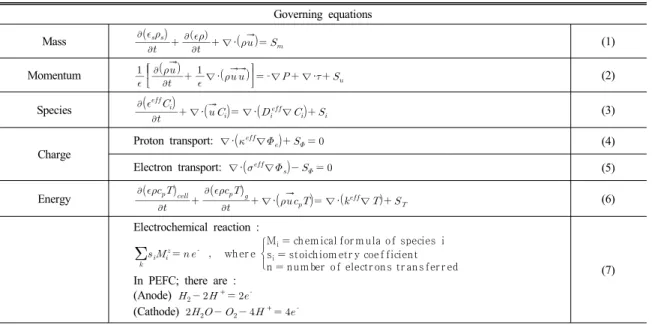
Table 1 PEFC cold start model governing equations
Governing equations
Mass
∇· (1)
Momentum
∇·
‐∇ ∇·
(2)
Species
∇· ∇·∇ (3)
Charge
Proton transport: ∇·∇ (4)
Electron transport: ∇·∇ (5)
Energy
∇· ∇·∇ (6) Electrochemical reaction :
wh er e
Mi ch em ical for m u la of species i si stoich iom etr y coef ficien t n n u m ber of electr on s tr an s fer r ed In PEFC; there are :
(Anode) + (Cathode) +
(7)
Table 2 PEFC cold start model source terms
Source/Sink terms
Mass
In the anode CLs : ‐
∇·∇ ∇·
(8)In the cathode CLs :
∇·∇
∇·
(9)Momentum In the GDL/CLs : ‐
(10)
In the membrane : (11)
Species
In the CLs for water : ‐
∇·
(12)In the GDLs for water : (13)
In the CLs for other species : ‐
(14)
Charge In the CLs : (15)
Energy
In the CLs :
(16)
In the GDLs :
(17)
In the membrane :
(18)
리고 공기극 촉매층의 구성의 변화가 저온시동 성능 에 미치는 영향도 함께 고려되었다. 본 연구는 자동 차용 연료전지 연구에서 시급히 해결해야 할 저온시 동 과제의 이론적 토대를 이룰 것이다.
2. 저온시동 모델
2.1 지배방정식 및 생성항
본 연구에서는 Ko 등10)에 의해 개발된 3차원 다상
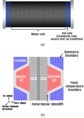
(a)
(b)
Fig. 1 Schematic of a PEFC stack (a) and mesh configuration of PEFC (b)
비정상 PEFC 저온시동 모델을 기반으로 하고 있다.
Ko 등이 개발한 저온시동 모델은 Tajiri 등13,14)의실 험데이터를 이용하여 다양한 작동조건에 대해 검증 되었다. PEFC 저온시동 모델은 Ko등10,11)의 논문에 상세하게 소개되었으므로 본 논문에서는 지배방정식 과 그 생성항들만을 Table 1, Table 2을 통해 간략하 게 요약하였다.
2.2 경계 조건
연료극과 공기극 채널(channel)로 유입되는 속도는 식 (19)∼(20)와 같이, 각각의 양론계수(stoichiometric ratio) , 작동전류밀도 와 가스채널의 단면적 및 의 함수로써 표현되었다.
ina
(19)
inc
(20)
또한 Fig. 1과 같이 스택(stacks) 내부에 위치한 중간 셀의 경우 좌・우면의 열 경계조건을 평형조건(symmetric boundary)로 두고 계산하였고, 엔드플레이트(end plate) 와 접한 엔드셀(end cell)의 경우 외부에 노출된 상태 를 고려하여 일정한 열속값(convective boundary)을 주어 계산하였다. 셀 위치를 위한 스택(stacks)개요도 및 기하학적 형상과 격자는 Fig. 1에 나타내었다.
2.3 저온시동 모델 시뮬레이션
본 연구에서 사용된 3차원 다상 비정상 PEFC 저온시 동 모델은 상업용 전산유체(computational fluid dynamics, CFD) 해석 패키지인 Ansys-Fluent v.13을 이용하여 실 행되었으며, 질량(mass), 운동량(momentum), 화학종 (chemical species), 전하(charge) 보존방정식(conservation equation)들 및 관련된 생성항(source term)들은 유저 코드기능을 이용하여 코드화 되었다. 확산층, 촉매
층, 전해질 막에서의 격자수는 기존의 연구결과를 참 조하였다2). 본 모델의 수렴조건은 각 수치 셀의 질 량, 운동량, 화학종, 전하 및 에너지의 최대 잔류값 (maximum residual)을 10-6이하로 설정하고, 각 시간 간격(time step)은 0.5초 이하, 시간 간격 당 반복계산 횟수는 500회 이상으로 하여 셀전압이 0.3V이하로 내려갈 때 까지 계산을 수행하였다.
3. 결과 및 고찰
본 연구에서 이용한 셀의 물성치와 작동조건 및 형상 의 치수는 Table 3에 요약되었고, 시뮬레이션(simulation) Case들은 Table 4에 정의되어있다. Table 4에 나타나 있는 Case들은 MEA설계변수의 영향성을 알아보기 위해 분류되었으며 Case 1은 공기극 촉매층 내 이오 노머(ionomer)의 분율, Case 2는 공기극 촉매층의 두 께, Case 3은 전해질 막의 두께가 각각 변화됨을 알
Table 3 Cell dimensions, operating conditions and material properties
Cell dimensions
Description Value Description Value
Anode/Cathode channel/rib width 1×10⁻³/1×10-3 m Anode/Cathode channel height 1×10⁻³ m Thickness of the anode/cathode GDLs 0.3×10⁻³ m Thickness of the membrane 0.03×10⁻³ m
Cell length 0.1 m Thickness of the
anode/cathode CLs 0.01×10⁻³ m Operating conditions
Description Value Description Value
Anode inlet pressure Atmospheric Cathode stoichiometry 2
Anode stoichiometry 2 Cathode O2 mole fraction 0.21
Anode H2 mole fraction 1 Cell operating temperature -30℃
Cathode inlet pressure Atmospheric Operating current density 1000 A/m2
Material properties
Description Value Description Value
Thermal conductivity of the GDL10) 1.5 W/m・K Heat capacity of the GDL11) 568 kJ/m3・K Thermal conductivity of the CL10) 1.2 W/m・K Heat capacity of the CL11) 3300 kJ/m3・K Thermal conductivity of the BP10) 20 W/m・K Heat capacity of the BP11) 2390 kJ/m3・K Thermal conductivity of the membrane10) 0.95 W/m・K Heat capacity of the membrane11) 1650 kJ/m3・K Effective electronic conductivity in the GDL10) 300 S/m Porosity GDLs11) 0.6 Effective electronic conductivity in the CL10) 300 S/m Permeability of GDLs11) 1×10-12 m2 Effective electronic conductivity in the BP10) 2×10⁻⁴ S/m Permeability of CLs11) 1×10-13 m2 Equivalent weight of the electrolyte in the membrane10) 1.1 kg/mol Dry membrane density10) 1980 kg/m3
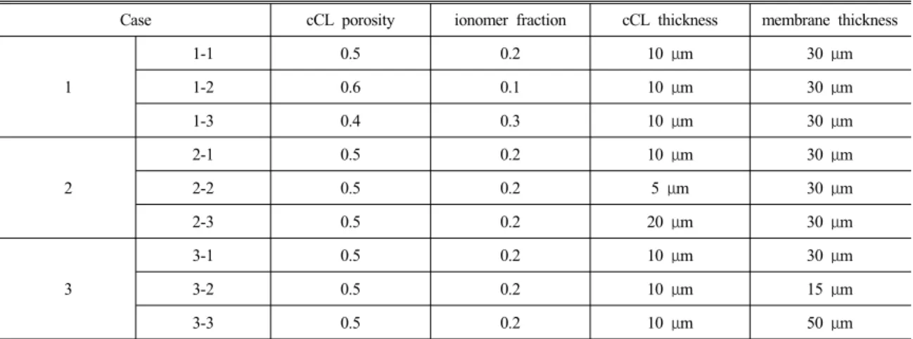
Table 4 Simulation cases
Case cCL porosity ionomer fraction cCL thickness membrane thickness
1
1-1 0.5 0.2 10 μm 30 μm
1-2 0.6 0.1 10 μm 30 μm
1-3 0.4 0.3 10 μm 30 μm
2
2-1 0.5 0.2 10 μm 30 μm
2-2 0.5 0.2 5 μm 30 μm
2-3 0.5 0.2 20 μm 30 μm
3
3-1 0.5 0.2 10 μm 30 μm
3-2 0.5 0.2 10 μm 15 μm
3-3 0.5 0.2 10 μm 50 μm
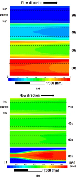
(a)
(b)
Fig. 2 (a) Evolution of (a) ice fraction contours in the cathode catalyst layer and current density distributions in the membrane for Case 1-1
수 있다. 특히 Case 1에서는 이오노머 분율과 기공도 (porosity) 합이 70%로 일정하다는 가정 하에 이오노 머 분율이 변하기 때문에 이오노머 분율이 증가할 때 촉매층 기공도는 자동적으로 감소함을 알 수 있다.
3.1 3차원 시뮬레이션 결과
기준이 되는 Case 1-1에 대하여 공기극 촉매층에 서 thru-plane 방향 중간지점의 얼음축적분율 및 전 해질 막에서 thru-plane 방향 중간지점의 전류밀도분 포도를 Fig. 2(a)와 Fig. 2(b)에 나타내었다. Fig. 2(a) 의 분포도를 통하여 80초까지 공기극 촉매층에서 얼 음의 축적분율이 지속적으로 증가하는 경향을 확인 할 수 있다. 또한, 랜드(land)부근의 얼음의 축적분율 이 채널부근의 얼음의 축적분율보다 항상 크게 나타 난다. 이는 생성된 물은 채널을 통하여 쉽게 제거되 는 반면에 랜드(land)부근에서는 물의 축적이 용이하 기 때문이다. 80초 분포도에서는 공기극 촉매층의 얼 음의 축적분율이 1에 도달하여 산소전달을 막고 결 국 셀이 작동 중지에 이르게 되는 것을 확인 할 수 있다. Fig. 2(b)는 전해질 막 에서의 전류밀도 분포를 나타낸다. 20~60초의 전해질 막에서의 전류밀도분 포는 상당히 균일하게 나타나지만 작동중지시점인 80 초에서는 상당히 불균일하게 변함을 알 수 있다. 이는 얼음의 축적분율이 1에 도달하는 랜드(land)하단에서 는 반응물의 물질전달손실에 의해 전류밀도값이 크게 감소하기 때문이다. 그러므로 저온시동 시 갑작스런 불균일한 전류밀도 분포는 촉매층 얼음축적에 기인 한 작동중지의 징후임을 본 시뮬레이션(simulation) 결과물을 통해 알 수 있다.
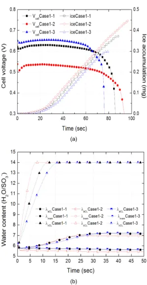
3.2 공기극 촉매층 조성의 영향성
Fig. 3(a), (b)는 저온시동 시 공기극 촉매층 내 이 오노머(ionomer)의 양이 다를 때(Case 1-1, Case 1-2, Case 1-3) 엔드셀(end cell)에서의 전압 및 얼음축적 량과 연료극 및 공기극 촉매층과 전해질막에서의 물 함량의 변화를 각각 나타낸다. 먼저 이오노머 양이 가장 적은 Case 1-2의 셀 성능은 촉매층에서의 옴 (ohm) 저항의 증가로 가장 낮지만 저온시동 능력은 가장 우수하여 저온시동 작동중지시점이 95초로 가 장 늦고 결과적으로 얼음 축적량이 0.45mg으로 가장 큼을 알 수 있다. 이는 이오노머(ionomer) 분율이 적
(a)
(b)
Fig. 3 Effects of cathode catalyst layer composition in the end cell: (a) cell voltage and ice accumulation in the cCL (b) water content in the aCL, cCL and membrane
(a)
(b)
Fig. 4 Effects of cathode catalyst layer composition in the middle cell: (a) cell voltage and temperature in the cCL (b) water content in the aCL, cCL and membrane
을수록 기공도가 증가하고 따라서 생성된 얼음을 저 장 할 수 있는 능력이 향상되기 때문이다. 반면 Fig.
3(b)에서는 공기극 촉매층 내 이오노머(ionomer)에서 흡수할 수 있는 물의 양은 Case 1-2가 가장 적어 저 온시동 초반에 가장 빠르게 증가하여 7.5초 후에 포 화됨을 알 수 있다. 그러므로 Case 1-1, Case 1-2, Case 1-3에서의 저온시동 능력은 공기극 촉매층의 기공도 의 크기에 의해 결정된다는 사실을 알 수 있다.
Fig. 4(a), (b)에서는 Case 1-1, Case 1-2, Case 1-3 에 대한 중간셀에서의 전압 및 셀 온도와 연료극 및
공기극 촉매층과 전해질막에서의 물 함량의 변화를 각각 나타낸다. 먼저 영하 30℃ 저온 시동 시 엔드셀 (end cell)과 달리 중간셀에서는 저온 시동이 모두 성 공적임을 알 수 있다. 이는 중간셀은 외부로의 열손 실이 적기 때문에 공기극 촉매층의 얼음 축적 속도 보다 발열에 의한 셀 온도 상승속도가 커 셀 온도가 0℃ 이상으로 성공적으로 증가하기 때문이다. Case 1-1, Case 1-2, Case 1-3 결과물들을 비교할 때 중간 셀에서도 Case 1-2의 저온시동 능력이 가장 우수함 을 알 수 있다. 이는 Case 1-2이 공기극 촉매층에서
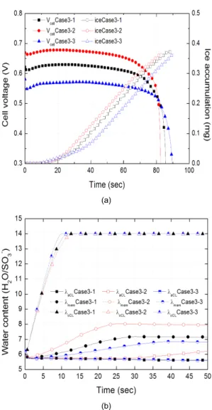
(a)
(b)
Fig. 5 Effects of cathode catalyst layer thickness in the end cell: (a) cell voltage and ice accumulation in the cCL (b) water content in the aCL, cCL and membrane
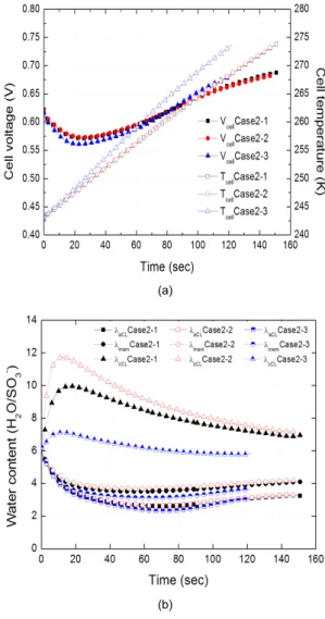
(a)
(b)
Fig. 6 Effects of cathode catalyst layer thickness in the middle cell: (a) cell voltage and temperature in the cCL (b) water content in the aCL, cCL and membranel
의 옴(ohm) 저항 증가로 발열량이 가장 크며 이로 인 해 셀 온도 상승이 가장 빠르기 때문이다.
Fig. 4(b)는 엔드셀(end cell)의 Fig. 3(b)와 달리 저 온시동 동안 공기극 촉매층에서의 물 함량이 감소하 는 경향을 보여준다. 이는 계속적인 온도의 상승으로 물이 공기극에서 연료극으로 전달되는 역확산률이 증가하기 때문이며 공기극 촉매층의 얼음생성 또한 억제하는 효과를 가져온다.
3.3 공기극 촉매층 두께의 영향성
Fig. 5(a), (b)는 저온시동 시 공기극 촉매층 두께 가 다를 때(Case 2-1, Case 2-2, Case 2-3) 엔드셀(end cell)에서의 전압 및 얼음축적량과 연료극 및 공기극 촉매층과 전해질막에서의 물 함량의 변화를 각각 나 타낸다. Case 2-1, Case 2-2, Case 2-3 비교할 때 공기 극 촉매층의 두께가 증가 할수록 얼음이 생성되기 시작되는 시점이 늦어지고, 작동중지시점 까지 축적 할 수 있는 얼음의 양이 많아져 저온시동 능력이 우
(a)
(b)
Fig. 7 Effects of membrane thickness in the end cell: (a) cell voltage and ice accumulation in the cCL (b) water content in the aCL, cCL and membrane
(a)
(b)
Fig. 8 Effects of membrane thickness in the middle cell: (a) cell voltage and temperature in the cCL (b) water content in the aCL, cCL and membrane
수해짐을 Fig. 5(a)를 통해 알 수 있다. 또한 공기극 촉매층 두께가 가장 두꺼운 Case 2-3에서 저온시동 시 가장 높은 성능이 예측되었다. 이는 공기극 촉매 층의 두께 증가에 의한 저항손실(ohmic loss) 증가보 다 얼음의 축적분율(ice fraction) 증가에 의한 물질전 달손실(mass transport loss)의 영향성이 더 크다는 사 실을 암시한다. Fig. 5(b)에서는 공기극 촉매층 두께 가 증가할수록 이오노머(ionomer) 절대양이 많아져 많은 양의 물을 함유할 수 있서 초반에 물함량이 낮 게 나타나며, 포화되는 시점도 가장 늦음을 알 수 있
다. 즉 촉매층 두께가 20μm로 가장 두꺼운 Case 2-3 에서는 포화되는 시점이 20초로 가장 늦고 이 시점 이후부터 공기극 촉매층에 얼음이 생성되기 시작하 지만 촉매층 두께가 가장 얇은 Case 2-2(5μm) 경우 대략 5초 정도에 공기극 촉매층 물 합량이 포화되어 얼음 생성이 계시된다.
Fig. 6(a), (b)에서는 Case 2-1, Case 2-2, Case 2-3 에 대한 중간셀에서의 전압 및 셀 온도와 연료극 및 공기극 촉매층과 전해질막에서의 물 함량의 변화를 각각 나타낸다. 엔드셀(end cell)의 경우와 다르게 중
간셀의 저온 시동 시 셀 성능은 공기극 촉매층이 두 꺼울수록 더 낮게 나타나는데 이는 공기극 촉매층의 두께 증가에 의한 저항손실(ohmic loss) 증가 영향성 이 산소 전달 손실의 영향성 보다 더 크며 다시 말해 중간셀에서는 얼음 축적의 영향성이 미비하다는 사 실을 입증해준다.
3.4 전해질 막 두께의 영향성
Fig. 7(a), (b)는 저온시동 시 엔드셀(end cell)에서 의 전해질 막의 두께에 의한 영향성을 나타낸다. Fig.
7(a)로부터 전해질 막의 두께가 저온시동 시 성능에 상당한 영향을 미치지만 작동중지시점에는 별다른 영향을 주지 않는 사실을 알 수 있다. 즉, 작동중지시 점은 전해질 막의 두께보다는 공기극 촉매층 두께의 영향이 지배적임을 알 수 있다. Fig. 7(b)에서는 전해 질 막의 두께가 증가할수록 공기극에서 연료극으로 믈이 역확산되는 거리가 길어지기 때문에 전해질 막 에서의 물 함량이 낮게 나타나는 경향을 확인할 수 있다.
Fig. 8(a), (b)에서는 저온시동 시 중간셀에서의 전 해질 막의 두께가 셀 전압 및 온도, 그리고 물함량에 미치는 영향을 나타낸다. Fig. 8(a)에서 엔드셀(end cell)의 경우와 동일하게 중간셀에서도 전해질 막 두 께가 두꺼운 Case 3-3이 가장 낮은 성능을 보이는 것 을 확인할 수 있다. 이는 공기극에서 연료극으로 물 역확산이 억제되어 전해질 막 건조에 의한 옴(ohm) 저항이 커지기 때문이다. 결과적으로 전해질 막이 두 꺼울수록 저항 열(ohmic heat)이 많이 발생하여 셀 온도 또한 상승이 빠르게 나타나는 것을 확인할 수 있다. Fig. 8(b)에서 주목할 부분은 Case 3-1과 Case 3-2는 시간이 지날수록 전해질 막 물함량이 증가하 지만 Case 3-3은 저온시동 동안 전해질 막 물 함량이 감소하는 경향을 확인할 수 있다. 이는 전해질 막을 통한 물 역확산률 감소와 셀 온도상승률 증가의 복 합적인 영향에 의해 전해질 막 건조가 일어나기 때 문이다.
4. 결 론
본 연구에서는 3차원 다상 비정상 PEFC 저온시동 모델을 이용하여 공기극 촉매층의 구성, 공기극 촉매 층 및 전해질 막의 두께와, 스택(stacks) 내부의 셀 위 치가 저온시동 성능에 미치는 영향성에 대하여 전산 해석을 수행하였다. 본 연구를 통하여 얻은 결론을 정리하면 아래와 같다.
1) 연료전지 저온시동의 성공/실패 여부는 저온시동 시 발생하는 발열률 및 얼음생성률의 상대적 크 기에 의해 결정된다. 시뮬레이션(simulation)이 수 행된 모든 경우에 대하여 스택(stacks) 내부의 엔 드셀(end cell)은 열의 이용률 감소로 공기극 촉매 층 기공이 얼음으로 채워져 결국 셀 작동이 중지 되게 된다. 하지만 중간셀은 외부로의 열손실이 적기 때문에 공기극 촉매층의 얼음 축적 속도보 다 발열에 의한 셀 온도 상승속도가 커 저온 시동 이 모두 성공적으로 완료됨을 알 수 있다.
2) 공기극 촉매층의 이오노머(ionomer)양은 얼음 생성 시점에 밀접한 관련이 있으며, 촉매층 기공도는 셀 작동중지 시점과 밀접한 관련이 있음을 저온시동 시뮬레이션(simulation)을 통해 입증하였다. 즉 이 오노머(ionomer)양이 많아질수록 저온 시동 시 생 성되는 물을 흡수하는 양이 많아져 촉매층 내 얼 음이 생성되는 시점을 늦추는 효과가 있으며 기 공도가 커질수록 얼음 저장능력이 커져 작동중지 시점이 그 만큼 늦어지게 된다.
3) 전해질 막의 두께는 영하 30도 저온시동 시 그 미 치는 영향성이 미비한 것으로 판명되었다. 주요 원인은 극 저온에서의 전해질 막의 물 전달률 감 소에 기인한다. 즉 저온시동 시 셀의 저온시동 능 력은 전해질 막의 두께보다는 공기극 촉매층 두 께와 조성의 영향성이 지배적이라는 사실이 본 연구를 통해 밝혀졌다.
후 기
이 논문은 2010년도 정부(교육과학기술부)의 재원 으로 한국연구재단의 기초연구사업 지원을 받아 수 행된 것임(2010-0009406). 또한 현대기아자동차 및 현대엔지비의 연구비 지원에 감사드립니다(미래기술 연구 - 1101HKMFFME003).
참 고 문 헌
1. L. Mao and C. Y. Wang : “Analysis of Cold Start in Polymer Electrolyte Fuel Cells”, Journal of Electrochemistry society, Vol. 154, No. 2 2007, pp. 139-146.
2. L. Mao, C. Y. Wang and Y. Tabuchi : “A Multiphase Model for Cold Start of Polymer Electrolyte Fuel Cells”, Journal of Electrochemistry society, Vol. 154, No. 3, 2007, pp. 341-351.
3. F. Jiang, W. Fang and C. Y. Wang : “Non- isothermal cold start of polymer electrolyte fuel cells”, Electrochimica Acta, Vol. 53, 2007, pp.
610-621.
4. F. Jiang and C. Y. Wang : “Potentiostatic Start-Up of PEMFCs from Subzero Temperatures”, Journal of Electrochemistry society, Vol. 155, No.7, 2008, pp.
743-751.
5. K. Jiao and X. Li : “Three-dimensional multiphase modeling of cold start processes in polymer electro- lyte membrane fuel cells”, Electrochimica Acta, Vol. 54, 2009, pp. 6876- 6891.
6. H. Meng : “Numerical analyses of non-isothermal self- start behaviors of PEM fuel cells from sub- freezing startup temperatures”, International Journal
of Hydrogen Energy, Vol. 33, 2008, pp. 5738-5747.
7. H. Meng : “A PEM fuel cell model for cold-start simulation”, Journal of Power Sources, Vol. 178, 2008, pp. 141-150.
8. S. He and M. M. Mench : “One-Dimensional Transient Model for Frost Heave in Polymer Electrolyte Fuel Cells I. Physical Model”, Journal of Electrochemistry society, Vol. 153, No. 9, 2006.
pp. 1724-1731.
9. Y. Wang : “Analysis of the Key Parameters in the Cold Start of Polymer Electrolyte Fuel Cells”, Journal of Electrochemistry society, Vol. 154, No.
10, 2007, pp. 1041-1048.
10. J. H. Ko and H. C. Ju : “Comparison of numerical simulation results and experimental data during cold-start of polymer electrolyte fuel cells”, Applied Energy. in press.
11. J. H. Ko, W. G. Kim, T. W. Hong, D. M. Kim and H. C. Ju : “Impact of metallic bipolar plates on cold-start behaviors of Polymer Electrolyte Fuel Cells (PEFCs)”, Solid State Ionics. in press.
12. M. Khandelwal, S. H. Lee and M. M. Mench :
“One- dimensional thermal model of cold-start in a polymer electrolyte fuel cell stack”, Journal of Power Sources, Vol. 172, 2007, pp. 816-830.
13. K. Tajiri, Y. Tabuci and C. Y. Wang : “Isothermal Cold Start of Polymer Electrolyte Fuel Cells”, Journal of The Electrochemical Society, Vol. 154, No. 2, 2007, pp. B147-B152.
14. K. Tajiri, Y. Tabuchi, F. Kagami, S. Takahashi, K. Yoshizawa and C. Y. Wang : “Effects of operating and design parameters on PEFC cold start”, Journal of Power Sources, Vol. 165, 2007, pp. 279-286.