Introduction
Chicken is one of the most popular meats consumed by humans and its consumption in Korea has increased by 4% annually on average. This increase is due to the global trend of replacing beef and pork consumption with chicken, which is leaner and lower in fat than other meats. Currently, chicken cutting or processing into 20 to 25 pieces is done manually with rotary blades. Skilled workers can process 500 chickens each day based on an eight-hour day. However, manual processing has many problems such as high risk of accidents and hygiene problems due to handwork. Moreover, most of these skilled workers are elderly, which produces safety accidents during work. The number of laborers is also
diminished every year, which increases the demand on the chicken cutting device.
Kim et al. (2001) reported that consumers’ biggest concerns are meat quality and safety as consumers are more interested in meat quality than quantity due to changes in meat consumption trends. Thus, safer and more hygienic chicken cutting devices are required to satisfy the demands of consumers who have food safety concerns. According to KaygIsiz & Cevger (2010), chicken cutting work using an electric saw reduced the chicken meat loss rate by more than 15% compared to manual cutting processing via handwork using a knife, thereby increasing the company’s profits 11.37% due to cost reduction and increased productivity. As described above, an automatic chicken cutting machine that can automate cutting processing can improve company profits by further reducing production costs. Currently, large chicken processing enterprises in Korea import machines that were developed in the Netherlands.
Development of Automatic Chicken Cutting Machine
Duk Gam Woo1*, Yeong Jin Kim2, Hack kyu Lim2, Tae Han Kim1*
1School of Agricultural Civil & Bio-industrial Machinery Engineering, Kyoungpook National University, Daegu, 41566,
Republic of Korea
2School of Mechanical Engineering, Daegu University, Gyeongsan, 38453, Republic of Korea
Received: October 31th, 2018; Revised: November 29th, 2018; Accepted: November 30th, 2018
Purpose: Chicken cutting is done manually, which is inefficient, unhygienic, and carries a high accident risk during processing. This study develops and evaluates an automatic chicken cutting machine that suits small-scale workplaces. Methods: This study developed an automatic chicken cutting machine equipped with four traverse blades and two longitudinal blades. An experiment was conducted with various blade rotating speeds and tray feed rates to evaluate the machine’s performance. The chicken loss rate and chicken piece weights were measured to calculate the coefficient of variation (CV), thereby determining processing uniformity. Results: The optimal cutting conditions with the smallest chicken loss rate were 0.05 m/s tray feed speed and 18.8 m/s and 16.4 m/s for the traverse and longitudinal blades, respectively. The processing ran at 55.3 chickens per hour and the chicken pieces were more uniform when using the device than for hand-work processed pieces. Conclusions: The loss rate increased in proportion to the cutting-blade rotation speed due to the high cutting rate in meat. The loss rate also increased as the tray feed speed slowed because the cutting blade pushed the chicken meat. The tray feed speed should be increased to improve the amount processed per hour.
Keywords: Automatic cutting, Capacity of chicken cutting, Chicken, Cutting processing
https://doi.org/10.5307/JBE.2018.43.4.386 pISSN : 1738-1266
*Corresponding author: Duk Gam Woo, Tae Han Kim Tel: +82-33-769-5187, +82-53-950-5793;
Fax: +82-33-769-5199, +82-53-950-6780 E-mail: [email protected], [email protected]
However, such machines are expensive and too large for small chicken processing enterprises that ay process 2,000–5,000 chickens per day (Hazenbroek and De Vree, 2010). Thus, it is necessary to develop a chicken cutting device that suits the local circumstances.
Regarding previous studies on chicken cutting device developments, Heck (2006) proposed a chicken cutting device for boneless chicken breast by image processing using a digital speech interpolation scanner according to the meat use purpose and cutting the breast to a preferred thickness and shape using a water jet. However, their study is for the cutting processing of boneless chickens, which is different from the present study that aims to cut chicken meat with bones. Regarding studies on cutting process devices for chicken with bones, chicken cutting devices can be found that use blades, a press, and a band saw. In the blade method, chickens that are fed in the transverse direction are cut by a rotating blade. However, since chickens are not fixed during cutting, the cutting performance and processing work efficiency are degraded and uniform cutting is difficult (Kang, 2002). In the press method, chickens are damaged by the press during the cutting processing, and cutting performance is unsatisfactory (Kang, 2011). In the band-saw cutting devices, there is a work safety risk and cutting chickens with bones is difficult (Kang, 2013). However, commercialized chicken cutting devices are not readily available. Thus, this study develops an automatic chicken cutting device that cuts chicken contained in a tray using a bi-directional rotating blade. In addition, the cutting performance and work efficiency of the developed device and weight uniformity of the cut pieces are analyzed to evaluate the device performance.
Materials and Methods
Materials
The chickens used in the experiment were No. 10 Korean chickens (950–1,050 g) that were divided into right and left sides from the center after removing wings, feet, and neck as shown in Figure 1. Chicken cutting processing companies regularly perform pre-processing that cuts wings, feet, and neck from the chicken and divides the body into two from the center before cutting the chicken into further pieces. After this, workers put 20 to 25 chicken pieces in a pack, to make the total weight of
the chicken pieces constant, and distribute them to chicken franchises.
Development of the automatic chicken
cutting machine
Tray
A tray was fabricated to which the chickens would be fixed during cutting. The left and right sides of 20 chickens divided at the center were measured to fabricate a tray and the maximum width and length were respectively 127 mm and 269 mm on the left side and 120 mm and 256 mm on the right side. The average thickness was 20.8 mm (range: 7.4–35.2 mm) and the CV and standard deviation (SD) were 4.9% and 7.3 mm,
Figure 1. Chicken used in experiment
respectively. In this study, a tray was fabricated with the following dimensions: width 320 mm, length 270 mm, and depth 45 mm, as shown in Figure 2. In addition, the optimal cutting position was simulated to make the weight of pieces of chicken the most uniform when the chicken was divided into five pieces in the transverse direction. The simulation result determined the optimal transverse cutting position when the cutting blades were attached with the following gap distances: 41 mm, 38 mm, 39 mm, 34 mm, and 88.8 mm in the neck-to-tail direction. The optimal longitudinal cutting position was found when the cutting blades were attached at 54.1 mm at the left and right sides from the tray center in the longitudinal direction.
Driving motor selection
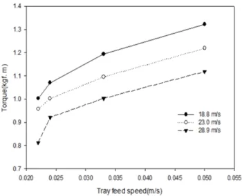
To select a drive motor for the chicken cutting device, torque was measured during chicken cutting using a torque sensor (YDSB–2 00KC, Setech, Korea) and the required power supply (PS) was calculated using Eq. (1). Here, T represents the torque (kgf·m), n represents the rotating speed (rpm), and P represents the power (PS). In the torque measurement experiment, torque was measured at the transverse cutting when the cutting load was high. In the experiment, the rotating speed of the transverse blade was set to 18.8 m/s, 23.0 m/s, and 28.9 m/s, and the tray feed speed was set to 0.022 m/s, 0.024 m/s, 0.03 m/s, and 0.05 m/s.
× · (1)
Feed and cutting devices
Figure 3 shows the feed device in which the tray was installed. As the tray is fed in, chickens are cut by the rotating transverse blade. The conveyor sprocket roller was made from polyoxymethylene, and its dimensions were 138 mm in diameter and 290 mm long. The sprocket's dimensions were 88 mm in diameter and 212 mm long and it was supported by two bearings to minimize vibration and noise. The dimensions of the shaft that rotates the sprocket was 392 mm long and 25 mm in diameter and the shaft was made of S45C.
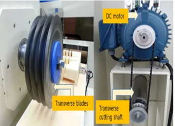
Figure 4 shows the transverse cutting device by which the chicken is divided into five pieces by four rotating transverse blades as a tray is fed in. Figure 5 is a picture of the longitudinal cutting device in which chicken in a tray is cut while two longitudinal blades are fed by a ball screw. Blade covers were installed in both the transverse and longitudinal cutting devices for worker safety. For the cutting blades, sawtooth and flat blades were used in the experiment, and the sawtooth blade had greater
Figure 3. Conveyor
Figure 4. Transverse cutting device
chicken loss than the flat blade in the cutting process. Thus, the cutting blade was set to the flat blade. The blade's diameter was 300 mm, its thickness was 2 mm, and the blade’s angle was set to 17°; It was made of high-speed steel.
Control device
Figure 6 shows the contactless position sensor (PR(T)18-5D, AutonicsCE, Korea) that ensures the accuracy of the longitudinal blade’s operating position after transverse cutting by controlling the tray’s stop position. Chickens are cut as the longitudinal cutting device is transferred after the tray is stopped by the sensor after transverse cutting. Figure 7 shows the sensor installation to control the position of the transferring longitudinal cutting device in which a sensor is installed at both ends at the left and right sides. The control device was configured to control the following items: power supply, longitudinal blade drive motor on/off, longitudinal blade rotating speed, longitudinal cutting device forward/backward, device automatic/ manual mode, transverse blade drive motor on/off,
transverse blade rotating speed, tray forward/backward, feed speed, and tray zero return.
Entire device
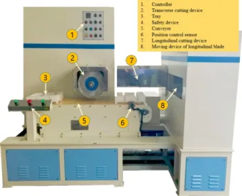
Figure 8 shows a picture of the complete automatic chicken cutting machine whose dimensions are: 2,200 mm wide, 1,260 mm long, and 1,509 mm high. It is smaller than existing types used in larger plants; thus, its size makes it suitable for smaller chicken processing plants that process 2,000–5,000 chickens per day. The cutting process is as follows: preparation work such as chicken input in the tray → turn on the power supply → transverse cutting → tray stop at the pre-set location using a proximity sensor → longitudinal cutting → work completion.
Performance of the automatic chicken
cutting machine
Loss rate
To measure the loss rate of the chickens during cutting using the automatic chicken cutting device, a range of rotating speeds of transverse and longitudinal blades were set to three levels as presented in Table 1. The minimum blade rotating speed (transverse blade at 18.8 m/s and longitudinal blade at 16.4 m/s) was the minimum speed at which the blades could cut chicken meat. Since four transverse blades divided the chicken into four pieces, the transverse blade rotating speed that could cut chicken meat was faster than that of the longitudinal blade, which cut the chicken into only two
Figure 6. Position control sensor for stopping tray
Figure 7. Position control sensor of moving device for longitudinal
pieces. The tray feed speed was set to four levels (0.022 m/s, 0.024 m/s, 0.033 m/s, and 0.050 m/s), changing the speed throughout the experiment. Five chickens were cut with each of the above conditions to verify the experimental results and the average loss rates were calculated and compared. The weights before and after cutting were measured to calculate the loss rate as presented in Eq. (2). Here, L refers to the loss rate, Wb
refers to the weight (g) before cutting, and Wa refers to
the weight (g) after cutting.
× (2)
Work efficiency
The work efficiency of the automatic chicken cutting machine was analyzed with the number of chickens processed per hour while changing a tray feed rate at the transverse and longitudinal blade rotating speeds that produced the minimum loss rate.
Weight uniformity of chicken pieces
To analyze the weight uniformity of chicken pieces, this study calculated the weights, coefficient of variation (CV), and standard deviation of pieces cut manually by chicken processing companies and pieces cut using the automatic chicken cutting device. To calculate the CV, the following Eq. (3) was used. The number of chickens used in each experiment was four.
∑ ∑
× (3)
CV: Coefficient of variation (%) n: Number of measured chickens
m: Average for each measured chicken (g) ∑: Sum of each measured chicken (g)
∑: Sum of the squared value for each measured
chicken (g)
Results and Discussion
Drive motor selection
The torque measurement results during cutting are shown in Figure 9, in which the maximum torque value was 1.322 kgf·m when the transverse blade rotating speed was 18.8 m/s and the tray feed speed was 0.050 m/s, and the minimum torque value was 0.813 kgf·m when the transverse blade rotating speed was 28.9 m/s and the tray feed speed is 0.022 m/s. Thus, the maximum power required for cutting was 3.5 PS. This study selected a 5 PS DC motor (HSX1004261, Hysoung, Korea) as the power supply source considering the measurement error, overload, and safety factor.
Performance of automatic chicken cutting
machine
Loss rate
Figure 10 shows the chicken loss rate according to the tray feed speed. As the feed speed increases, the loss rate decreases. If the tray feed speed was slow during chicken cutting, chickens were pushed away by the rotating blade without cutting, resulting in increased loss rate. Figure 11 displays the chicken loss rate according to the longitudinal and transverse blade rotating speeds in which the loss rate increases as the blade rotates faster. The increased loss rate was due to the chicken meat being chipped away during cutting as the blade rotated faster. Figure 12 is loss rate graph according to the blade rotation and feed speeds. When the blade rotating speed
Table 1. Blade rotating speed conditions
Blade direction Rotating speed (m/s) Level A Level B Level C Transverse blade 18.8 23.0 28.9 Longitudinal blade 16.4 19.8 24.8
Figure 9. Cutting torque comparison in accordance with change of the transverse blade speed and the tray feed speed
was Level A (transverse blade rotating speed 18.8 m/s and longitudinal blade rotating speed 16.4 m/s) and the tray feed speed was 0.05 m/s, the loss rate was the smallest at 2.3%, and when the blade rotating speed was Level C (transverse blade rotating speed 28.9 m/s and longitudinal blade rotating speed 24.8 m/s) and the tray feed speed was 0.02 m/s, the loss rate was the highest at 6.1%. Figure 13 shows the chicken before and after cutting using the automatic chicken cutting device.
Work efficiency
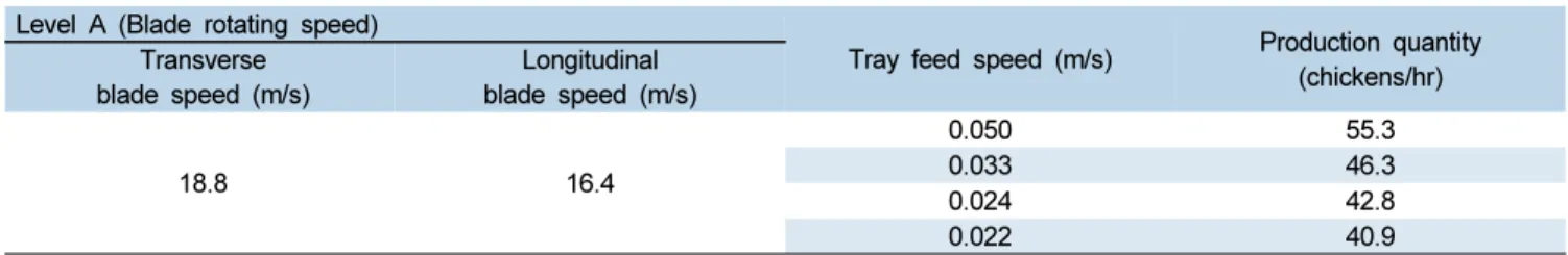
Table 2 presents the processing capacity of chickens per hour according to changes in tray feed speed when the blade rotating speed is Level A (transverse blade rotating speed 18.8 m/s, longitudinal blade rotating speed 16.4 m/s), and the lowest loss rate is revealed. The capacity of chicken processing was 55.3 chickens at a tray feed speed of 0.05 m/s, and 40.9 chickens at a tray feed speed of 0.022 m/s. Thus, if the tray feed speed increases, the number of chickens that can be cut per hour is expected to rise.
Weight uniformity of chicken pieces
Table 3 presents the weight measurement results of four chickens cut by hand to measure the weight uniformity of the chicken pieces. The number of pieces per chicken was 20 to 25, and CV and SD of each chicken were calculated. The calculation results showed that maximum and minimum CVs were 32.5% and 25.7%, and maximum and minimum SDs were 13.10 and 10.17, respectively. Table 4 presents the weight measurements of the cut pieces of four chickens in the following conditions: 18.8 m/s transverse blade rotating speed, 16.4 m/s longitudinal blade rotating speed, and 0.05 m/s tray feed speed, which were determined to be the optimal cutting conditions of the device.
The number of pieces per chicken was 20, and CV and SD of each chicken were calculated. The calculation results showed that maximum and minimum CVs were 14.1% and 5.5%, and maximum and minimum SDs were 6.76 and 2.71, respectively. The CVs and SDs of the chicken piece weights cut by the device were smaller than those cut by hand, resulting in more uniform weights of chicken pieces.
Figure 10. Effect of tray feed speed on the loss rate of cut chicken
Figure 11. Effect of blade rotating speed on the loss rate of cut chicken
Figure 12. Effect of blade rotating speed and tray feed speed on the loss rate of cut chicken
Conclusions
This study aimed to develop an automatic chicken cutting machine suitable for small meat processing companies. The machine consisted of a tray, feed device, cutting device, and control system. This study found the optimal cutting conditions that produced the smallest chicken loss rate during cutting by changing the rotating speeds of the bi-directional cutting blades and the tray
feed speed. It also evaluated the device performance with a comparison of chicken piece uniformity and capacity of processing per hour. The cut piece weight uniformity from the automatic device showed reduced CVs and SDs compared with those cut by hand, indicating that the piece weights cut by the automatic device were more uniform. The optimum cutting speed was found to be the following: 0.05 m/s of tray feed speed, 18.8 m/s of transverse blade speed, and 16.4 m/s of longitudinal
(a) (b)
Figure 13. Chicken cutting using the automatic chicken cutting device ((a) chicken contained in a tray before cutting, (b) chicken pieces after cutting)
Table 2. Capacity of chicken cutting per hour in accordance with change of tray feed speed
Level A (Blade rotating speed)
Tray feed speed (m/s) Production quantity (chickens/hr) Transverse blade speed (m/s) Longitudinal blade speed (m/s) 18.8 16.4 0.050 55.3 0.033 46.3 0.024 42.8 0.022 40.9
Table 3. Weight measurement of cut piece by chicken handwork cutting (unit: g)
Sample Pieces 1 2 3 4 Total 908.5 897.2 885.5 847.9 Mean 41.30 40.78 40.25 38.54 CV (%) 26.89 25.67 32.53 26.38 SD 11.1 10.47 13.1 10.17
Table 4. Weight measurement of cut piece by automatic chicken cutting (unit: g)
Sample Pieces 1 2 3 4 Total 878.1 893.7 841.6 865 Mean 48.94 43.36 40.1 47.81 CV (%) 5.54 11.01 13.23 14.13 SD 2.71 4.77 5.31 6.76
blade speed, and 55.3 chickens were processed at this speed. This study verified that the number of processed chickens increased when the tray feed speed was raised, and the cutting process is safer and more hygienic using the automatic chicken cutting machine.
Conflict of Interest
The authors have no conflicting financial or other interests.
References
Heck, B. 2006. Automated chicken processing: machine vision and water-jet cutting for optimized performance. IEEE Control Systems 26(3): 17-19.
https://doi.org/10.1109/MCS.2006.1636305 Hazenbroek, J. E. and A. H. De Vree. 2010. Method and
Apparatus for Automatic Meat Processing. U.S. Patent No. 20100317272.
Kang, S. G. 2002. Automatic cutting machine a chicken. Korea Patent No. 1020020072892 (in korea). Kang, C. S. 2011. A cutting apparatus for chicken. Korea
Patent No. 1020110050388 (in Korea).
Kang, S. J. 2013. Cutting device for meat. Korea Patent No. 2020130005957 (in Korea).
Kaygisiz, F. and Y. Cevger. 2010. Effects of marketing chicken meat as a whole or cut up on enterprise income. Turkish Journal of Veterinary and Animal Sciences 34(1): 17-23.
Kim, B. M., S. K. Cho, K. H. Song and Y. K. Kim. 2001. The
differentiated strategies for pork processing and marketing. Korean Journal of Food Marketing Economics 18(1): 131-154.
Kim, B. K., E. G. Hwang and S. M. Kim. 2010. Meat quality and sensory poperties of korean native black goat by different castration age. Korean Journal for Food Science of Animal Resources 30(3): 419-426 (In Korean, with English abstract).
https://doi.org//10.5851/kosfa.2010.30.3.419 Kim, T. H. and H. K. Lim. 2005. Development of vegetable
soybean thresher. Journal of Biosystems Engineering 30(3): 141-146 (In Korean, with English abstract). https://doi.org/10.5307/JBE.2005.30.3.141
Lee, J. T. and T. H. Kim. 2011. Studies on development of a chicken feet-bone remover (I) - analysis of design factor with chicken feet-bone remover. Journal of Biosystems Engineering 36(4): 252-256 (In Korean, with English abstract).
https://doi.org/10.5307/JBE.2011.36.4.252
Lee, J. T. and T. H. Kim. 2011. Studies on development of a chicken feet-bone remover(Ⅱ)- manufacture of chicken feet-bone remover. Journal of Biosystems Engineering 36(4): 257-266 (In Korean, with English abstract).
https://doi.org/10.5307/JBE.2011.36.4.257
Song, D. B., S. K. Lee and Y. K. Jung. 2003. Analysis of red pepper calyx cutting using a rotational cutter. Journal of the Korean Society for Agricultural Machinery 28(3): 209-216 (In Korean, with English abstract). http://doi.org/10.5307/JBE.2003.28.3.209