This content has been downloaded from IOPscience. Please scroll down to see the full text.
Download details:
IP Address: 203.255.172.21
This content was downloaded on 03/11/2016 at 05:12
Please note that terms and conditions apply.
You may also be interested in:
A piezoelectric pulse generator for low frequency non-harmonic vibration Hao Jiang and Eric M Yeatman
A novel piezoelectric energy harvester designed for single-supply pre-biasing circuit N Mohammad pour, D Zhu, R N Torah et al.
Electromagnetic Vibration Energy Harvester Using Springless Proof Mass and Ferrofluid as a Lubricant
S H Chae, S Ju, Y Choi et al.
An Equivalent Circuit Model for Electrostatic Energy Harvester utilized Energy Harvesting System K Minami, T Fujita, K Sonoda et al.
Performance enhancement of a low frequency vibration driven 2-DOF piezoelectric energy harvester by mechanical impact
M A Halim and J Y Park
Piezoelectric energy harvester interface with real-time MPPT A D T Elliott and P D Mitcheson
View the table of contents for this issue, or go to the journal homepage for more 2014 J. Phys.: Conf. Ser. 557 012094
Equivalent circuit model of an impact-based piezoelectric
energy harvester
S H Kim, S Ju, C H Ji and S J Lee
Department of Electronics Engineering, Ewha Womans University, 52, Ewhayeodae-gil, Seodaemun-gu, Seoul, Korea
E-mail: [email protected]
Abstract. This paper presents an equivalent circuit model of an impact-based piezoelectric
energy harvester. The harvester alternately generates two different shapes of damped-oscillating signals due to the asymmetric structure of the device. Those signals have strong high frequency components through mechanical impact from low frequency vibration. Equivalent circuit model with dual voltage source is proposed to precisely describe the behaviour of the harvester. The simulation results of the harvester with typical conversion circuits were compared with measurement data to verify the correctness of proposed model.
1. Introduction
Research on energy harvesting devices has been widely conducted on demand for sustainable and remote energy power supplies in applications such as implantable devices and wireless sensor networks [1, 2]. Ambient energy sources are, for example, sunlight, temperature difference, and vibration. Among harvesters using these sources, vibrational-to-electrical energy converters based on piezoelectric materials are drawing much attention because piezoelectric materials have large power densities and ease of use [1]. The energy generated by a piezoelectric harvester, however, is not adequate to be directly applied to loads. So a conversion circuit between a harvester and a load circuit is required to extract the maximum power from the harvester and transfer it to the load circuit efficiently.
To predict the operation of the interface circuit, an equivalent circuit model of the harvester is needed. Piezoelectric harvesters are often represented as a current source model with a resistor in parallel [3-5]. Although this model is simple, its usefulness is limited to the case of a single resistive load [1]. More accurate and analytical models, which reflect mechanical and structural characteristics of harvesters, have been also presented [1, 2]. These models generally assume a cantilevered beam type harvester excited by movements at its base, and cannot express the behaviour of an impact-based piezoelectric energy harvester reported by the authors precisely. The targeted harvester in [6] generates an asymmetric damped-oscillating signal based on indirect impact using a movable ball. Therefore a new circuit model is needed to account for specific voltage waveforms of the harvester.
This paper presents an equivalent circuit model of the impact-based piezoelectric energy harvester reported by the authors. Next section describes the structure of the harvester and characteristics of electrical signal generated from it.The proposed circuit model is presented and evaluated with respect to the measurement results. The final section draws conclusions.
2.1. Description of the harvester
The impact-based piezoelectric energy harvester [6], as shown in figure 1, consists of a freely movable ball within an aluminum housing and a cantilever-type beam. The beam is covered with piezoelectric material and has a proof mass at one end.When the harvester is shaken, the ball moves and impacts each sidewall of the case to enable the beam to vibrate. It generates higher frequency signal than the applied force, which could significantly increase the energy conversion efficiency by generating high frequency signal through mechanical impact from low frequency vibration.
Figure 1. A schematic of the targeted energy harvester using a ball and a cantilever-type beam.
To observe electrical responses of the harvester, a shaker exciting an attached device vertically was used. Open-circuit output voltage of the harvester was measured at 20 Hz excitation with 3g acceleration, which was known as the optimum condition in this harvester [6]. Figure 2(a) shows the open-circuit voltage was generated twice in one period of the applied low frequency vibration because the ball moved upwards and downwards in one cycle of its movement. Because the force of a collision
Figure 2. (a) A measured signal at open-circuit during 150 ms, (b) a measured vs. simulated positive-first voltage at open-circuit during 2 ms and (c) a measured vs. simulated negative-first voltage at open-circuit during 2 ms
at the bottom was not equal to that at the upper end, signals were induced in two different waveforms alternately. In addition, the second peak in the waveform was larger than the first peak due to the asymmetric structure of the device as shown in figure 2(b-c). The oscillating frequency of the generated signal through impacting was around 8.5 KHz. The signal gets attenuated almost exponentially after positive-negative peaks and returns to zero.
2.2. Equivalent circuit model
To depict the observed behavior, an equivalent circuit was built as shown in figure 3(a). It is composed of a mechanical portion and an electrical portion as was proposed by [7]. The mechanical system includes an inductor, Lm, a capacitor, Ck, and a resistor, Rd1, representing the mass, mechanical stiffness, and mechanical damping respectively. The electrical part consists of a capacitor, Cp, and a resistor, Rd2, to represent internal capacitance of the piezoelectric material and loss respectively. A transformer is used to model electromechanical coupling between the mechanical and electrical parts. Due to two asymmetric damped-oscillating signals of different amplitude and phase, however, two independent voltage sources, Vp and Vn, were used in this model instead of one sine wave source. As shown in figure 3(b), each voltage source generated two signals with opposite sign at intervals of an applied vibration.
(a) (b)
Figure 3. (a) An equivalent circuit model of the targeted energy harvester (b) each signal of two voltage sources
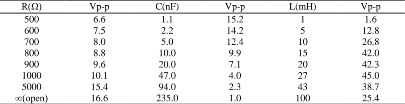
Table 1. Measured peak-to-peak voltages across various loads: resistance, capacitance and inductance. R(Ω) Vp-p C(nF) Vp-p L(mH) Vp-p 500 6.6 1.1 15.2 1 1.6 600 7.5 2.2 14.2 5 12.8 700 8.0 5.0 12.4 10 26.8 800 8.8 10.0 9.9 15 42.0 900 9.6 20.0 7.1 20 42.3 1000 10.1 47.0 4.0 27 45.0 5000 15.4 94.0 2.3 43 38.7 ∞(open) 16.6 235.0 1.0 100 25.4
Model parameters were determined by comparing results of Pspice simulation with experimental data, which were conducted by changing loads: inductors, capacitors and resistors. Table 1 lists the measured peak-to-peak voltages across various loads. Figure 4 shows that simulated voltages in the case of capacitive and inductive load conditions are very well-matched with the measurement data. 3. Experimental results
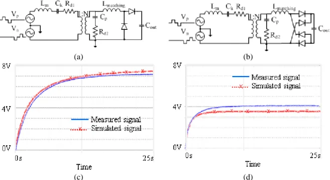
A voltage doubler and a full-bridge converter in figure 5(a,b) were tested to verify the model. SB140 diodes from VISHAY were used as rectifiers. The output capacitor value was 22 uF, and a 27 mH
(a) (b)
(c) (d)
Figure 4. Measured vs. simulated signals during 1.5ms (a) a positive-first voltage across a load capacitor C = 20 nF, (b) a negative-first voltage across a load capacitor C = 20 nF (c) a positive-first voltage across a load inductor L = 27 mH, and (d) a negative-first voltage across a load inductor L = 27 mH
(a) (b)
(c) (d)
Figure 5. (a) a voltage doubler, (b) a full-bridge rectifier, (c) measured vs. simulated output signals of a voltage doubler, and (d) measured vs. simulated output signals of a full-bridge rectifier
inductor was used as a matching circuit. Measured and simulated voltages across the capacitor are shown in figure 5(c, d). The output of a voltage doubler increased more slowly and produced higher steady-state voltage than that of full-bridge converter in both cases. Figure 5(c, d) shows good agreement between measured data and simulation results.
4. Conclusion
This paper suggests an equivalent circuit model that is tailored to the behavior of an impact-based piezoelectric energy harvester. The harvester alternatelygenerates two asymmetric damped-oscillating signals of different amplitude and phase at intervals of a vibration. Proposed circuit model includes two independent voltage sources as well as mechanical and electrical equivalent components to describe the behavior. This model is validated through PSpice simulations and proven to be quite accurate compared with experimental data.
Acknowledgments
This work was supported by the Ewha Global Top 5 Grant 2013 of Ewha Womans University. References
[1] Erturk A 2009 Electromechanical modeling of piezoelectric energy harvesters. In: Dept. Engineering Mechanics Virginia Polytechnic Institute and State University, Blacksburg, VA [2] Yang Y and Tang L 2009 Equivalent circuit modeling of piezoelectric energy harvesters Journal
of Intelligent Material Systems and Structures 20 2223-35
[3] Elliott A D T, Trice M R and Mitcheson P D 2012 Implementation of single supply pre-biasing with sub-35μw control overhead for piezoelectric energy harvesting Proc. PowerMEMS 2012 [4] Dicken J, Mitcheson P D, Stoianov I and Yeatman E M 2012 Power-extraction circuits for
piezoelectric energy harvesters in miniature and low-power applications Power Electronics, IEEE Transactions on 27 4514-29
[5] D'Hulst R, Sterken T, Puers R, Deconinck G and Driesen J 2010 Power processing circuits for piezoelectric vibration-based energy harvesters Industrial Electronics, IEEE Transactions on 57 4170-7
[6] Ju S, Chae S H, Choi Y, Jun S, Park S M, Lee S, Lee H W and Ji C-H 2014 Proc. APCOT 2014, pp 13-3
[7] Roundy S and Wright P K 2004 A piezoelectric vibration based generator for wireless electronics Smart Materials and structures 13 1131