저작자표시-비영리-변경금지 2.0 대한민국 이용자는 아래의 조건을 따르는 경우에 한하여 자유롭게
l 이 저작물을 복제, 배포, 전송, 전시, 공연 및 방송할 수 있습니다. 다음과 같은 조건을 따라야 합니다:
l 귀하는, 이 저작물의 재이용이나 배포의 경우, 이 저작물에 적용된 이용허락조건 을 명확하게 나타내어야 합니다.
l 저작권자로부터 별도의 허가를 받으면 이러한 조건들은 적용되지 않습니다.
저작권법에 따른 이용자의 권리는 위의 내용에 의하여 영향을 받지 않습니다. 이것은 이용허락규약(Legal Code)을 이해하기 쉽게 요약한 것입니다.
Disclaimer
저작자표시. 귀하는 원저작자를 표시하여야 합니다.
비영리. 귀하는 이 저작물을 영리 목적으로 이용할 수 없습니다.
변경금지. 귀하는 이 저작물을 개작, 변형 또는 가공할 수 없습니다.
Ph.D. DISSERTATION
Design of Multicomponent Metal Alloy Electrocatalysts for Improving
Electrochemical Performance
고효율 촉매전극을 위한 다원계 금속 합금 전기 촉매 연구
By
Hoonkee Park
Design of Multicomponent Metal Alloy Electrocatalysts for
Improving Electrochemical Performance
Advisor: Prof. Ho Won Jang
By Hoonkee Park
A thesis submitted to the Graduate Faculty of Seoul National University in partial fulfillment of the requirements
for the Degree of Doctor of Philosophy Department of Materials Science and Engineering
December 2019
Approved by
Chairman of Advisory Committee: Yong-Chang Joo Vice-Advisory Committee: Ho Won Jang
Advisory Committee: Jin Young Kim Advisory Committee: Kim Dong Wan
Abstract
Widespread application of electrochemical water splitting for energy conversion is largely dependent on the progress in developing not only efficient but also cheap and scalable electrocatalysts. Transition metal based metal oxides/hydroxide, alloys which can be synthesized with scalable technique such as electrochemical deposition are promising candidate for efficient electrocatalysts. Among the various metal candidates, Ni-based metal oxide/hydroxide, metal alloys have become a hot topic for electrochemical hydrogen generation by water oxidation. However, the actual conversion efficiency achieved with Ni-based electrocatalysts is considerably less than the noble metal based electrocatalysts because of drawbacks such as relatively low stability and slow kinetics of oxygen evolution reaction. In this respect, diverse engineering strategies such as
strategies were conducted to accomplish high efficiency near or over the precious metal based electrocatalysts for practical issue.
The first study reports the correlation between surface grain boundary density and water splitting efficiency based on single FCC phase binary NiFe alloy synthesized by arc-melting and electrodeposition. Among various metal alloys, NiFe alloy is the promising electrocatalysts to replace noble metal in terms of oxygen evolution reaction. And this study revealed that the oxygen evolution reaction activity of bare NiFe alloys can be changed drastically by controlling the surface grain boundary density. Under the extremely increased grain boundary density, a NiFe alloy electrocatalysts can lead to a low overpotential for current density 10 mA/cm2(300mV) and extremely high electrochemical surface area (ECSA) than micrometer-size grain NiFe alloy without additional catalyst. Electron backscatter diffraction and X-ray diffraction shows that single FCC phase NiFe alloy are successively synthesized by arc-melting and electrodeposition. This systematic study provides a viewpoint on the crucial role of the grain boundary on activity of oxygen evolution reaction, and the proposed concept is applicable to various metal alloy systems.
The second study handles the overall water splitting and hydrogen
splitting electrocatalysts, followed by the PV-EC system assisted by perovskite/Si tandem solar cell. Using facile and low cost synthesis, anodization and electrodeposition, electrocatalysts are properly synthesized to maximize the surface area and stability. High-performance perovskite/Si tandem cell attributed to extremely increase the operating current density of the combined system achieve a value of 14.24 mA/cm2, ηF= 100% and Jsc= 14.2 mA/cm2, the solar-to-hydrogen (STH) efficiency was determined to be 17.52%. The appropriate combination of oxygen evolution catalysts, hydrogen evolution catalysts and solar cells for PV-EC system enable to break new ground for development of low-cost, highly efficient hydrogen generation devices.
The third is introduction of medium entropy alloys (MEAs) to enhance stability and electrochemical efficiency and surface reaction kinetics by controlling the composition. The synergistic effect of newly explored
process like andization and CV activation achieve a remarkably reduced overpotehtial for current density of 10 mA/cm2., from 475 mV to 184 mV.
Improved electrochemical activity is closely related to the increased surface area originate from anodization and substantial shifts in chemical oxidation that derive from the CV activation process. Proposed concept has considerable potential to explore new efficient water splitting electrocatalysts. Combined spectroscopic analysis and electrochemical study can reveal the clear relationship between the surface chemical oxidation derived from CV activation and oxygen evolution properties for water oxidation.
In this thesis, devierse approaches such as nanostructure, grain size control, oxygen evolution catalyst and medium entropy alloys are cove red to make breakthrough for transition metal based electrochemical w ater splitting. This systematic study provides general strategy for enabl ing new active non-noble metal electrocatalyst and is applicable to ov erall hydrogen generation system.
Keyword: Metal hydroxide, Electrochemical water splitting, NiFe, Medium Entropy Alloy, Nanostructure, Electrocatalyst, Electrodeposition
Student Number: 2013-22476
Hoonkee Park
Table of Contents
Abstract...1
Table of Contents...5
List of Tables...6
List of Figures...8
Chapter 1... 13
Electrochemical water splitting: Basic principles... 13
1.1 Introduction... 14
1-2. Electrolysis Water Splitting System... 17
1-3. Scope and objectives of the thesis... 21
1-4. Reference... 24
2-5. References... 46
Chapter 3... 50
Solution processed electrocatalysts with nanometer scale grain using earth abundant elements for overall water splitting reaction... 50
3-1. Introduction... 51
3-2. Experimental method and characterization... 57
3-3. Results and discussion... 64
3-4. Conclusion... 82
3-5. References... 83
Chapter 4... 92
4-1. Introduction... 93
4-2. Experimental method and characterization... 95
4-3. Results and discussion... 97
4-4. Conclusion...104
4-5. References...106
6. Summary...109
Abstract (in Korean)...111
List of Tables
Table 3-1Comparison between our results and various PV-EC systems that have been reported elsewhere.
.
List of Figures
Figure 1-1 Sustainable paths to produce hydrogen from renewable energy.
Figure 1-2 Oxygen and hydrogen evolution reaction (OER and HER) for overall water splitting.
Figure 1-3. Various strategies to enhance water splitting activities of non- noble metal based electrocatalysts.
Figure 2-1 Schematic illustration of fabrication process for various grain size NiFe binary alloy.
Figure 2-2 Schematic illustration of electrodeposition process for nanometer scale grain size NiFe binary alloy.
Figure 2-3Schematic illustration of SPECM for in-situ observation of water splitting at NiFe binary alloy surface.
Figure 2-4 (a), (b) is the high resolution TEM images of 20μm grain and 440μm grain, respectively. (c) is X-ray diffraction patterns of different samples. (d), (e) show the EBSD images of 20μm grain and 440μm grain.
Figure 2-5 (a) Linear sweep voltammograms measured in 1 M NaOH at a scan rate of 10 mV/s for micrometer scale grain sized NiFe binary alloys. (b)
EIS measurement of micrometer scale grain sized NiFe binary alloy at 1.5V vs. RHE.
Figure 2-6 (a) Linear sweep voltammograms measured in 1 M NaOH at a scan rate of 10 mV/s for all samples. (b) EIS measurement of NiFe binary alloy at 1.5V vs. RHE for all samples.
Figure 2-7 Tafel plot of various grain sized NiFe binary alloys.
Figure 2-8 Charge transfer steps of typical metal hydroxide.
Figure 2-9 Electrochemical surface area measurement using double layer capacitance.
Figure 2-10 SPECM measurement of 440 μm grain and nanometer scale grain NiFe binary alloys.
Figure 3-1 Sketch diagram of electroforming process to make an NiFe alloy foil. Cathode electrode was rolling with continuous supplied bath solution,
anodization of the metal alloy substrate for the synthesis of more efficient electrodes with long-term stability.
Figure 3-3 Structural characterization of the NiFe alloy, NiFe (oxy)hydroxide films and Ni4Mo films on the NiFe alloy. (a), (b), (c) 3- dimensional atomic force spectroscopy images of bare NiFe alloy, NiFe (oxy)hydroxide films, and Ni4Mo films. (d), (e), (f) SEM images of bare NiFe alloy, NiFe (oxy)hydroxide films, and Ni4Mo films, respectively. The high-resolution TEM images of (g) NiFe (oxy)hydroxide and (h) Ni4Mo film. The SAED patterns for the synthesized films are displayed in the insets of (g), (h).
Figure 3-4 XRD characteristics of the NiFe (oxy)hydroxide films and electrodeposited NiMo films.
Figure 3-5 Electrochemical performance of different catalyst electrodes as characterized by linear sweep voltammetry in 1 M NaOH aqueous electrolyte. (a) OER characteristics of different catalyst electrodes in a three-electrode configuration scanned in the direction from the positive to the negative potential on the RHE scale. (b) Tafel slopes for the OER electrode and (c) HER characteristics for the different catalyst electrodes in a three-electrode configuration scanned in the direction from the negative to
the positive potential. (d) Tafel slopes for the HER electrode. All scan rates were 1 mV s−1.
Figure 3-6 2 electrode water splitting properties combining with a conventional 1.5 V battery. (a) Current density and (b) NiFe (oxy)hydroxide/NiMo water splitting system driven by an ~1.5 V AAA battery.
Figure 3-7 Chemical characterization of the NiFe (oxy)hydroxide and Ni4Mo electrocatalysts. (a) and (b) XPS spectra for Fe and Ni before and after anodization. (c) Raman spectra for the bare NiFe alloy and NiFe (oxy)hydroxide films, (f) FT-IR spectra for the bare NiFe alloy and NiFe (oxy)hydroxide films. (d) and (e) the Ni and Mo XPS spectra for the Ni4Mo films.
Figure 3-8 Combination of the silicon tandem cell with NiFe (oxy)hydroxide/NiMo electrodes for water splitting. (a) Overall water
The aperture size of the tandem cell was 0.1875 cm2, and the catalyst electrode areas were ~2 cm2 each. (e) Current density–time curve of the integrated water splitting device without external bias under chopped simulated AM 1.5G 100 mW cm−2illumination.
Figure 4-1 Schematic illustration of conventional alloy and medium entropy
alloy.
Figure 4-2 EBSD images of fabricated HEA and MEAs.
Figure 4-3 X-ray diffraction patterns of HEA and MEAs.
Figure 4-4 Hydrogen evolution reaction of HEA and MEAs.
Figure 4-5 Oxygen evolution reaction of HEA and MEAs.
Figure 4-6 Oxygen evolution reaction of Fe60(CoNi)30Cr10 MEAs after anodization and CV activation
Figure 4-7 SEM and TEM images of (a) Bare Fe60(CoNi)30Cr10MEAs, (b) anodized MEAs, and (c) CV activated MEAs after anodization.
Chapter 1
Electrochemical water splitting: Basic principles
1.1 Introduction
In every aspect of our lives, we intensively use the fossil fuels and chemicals, which have limited amount of reserves. With the rapidly growing industry and population, the indiscriminate use of energy and materials only lead to the threat of a dearth of supply and rising costs. For instance, energy consumption is expected to rise by 56 % worldwide by 2040 with close to 80 % provided by fossil fuels.[1-3] Considering that the population and industrial requirement is continuously increased, we should find a wise solution in this trend to maintain the sustainable development. The possible solution that we overcome current crisis is convert infinite resource into useful energy, like from solar energy to electricity, to maintain a balance between production and consumption.
1-1-1. Sustainable and Future energy sources
The depletion of conventional fossil fuels and increasing energy crisis requires the development of newly and sustainable energy sources. Thus, it is extremely urgent to search viable alternative renewable energy to replace fossil fuel. Renewable energy sources include solar, wind, wave and
TW, for more than other form of energy sources. Therefore, it can easily meet the world’s total energy consumption. However, solar energy has two serious disadvantages, i.e., low‐energy density, fluctuations with weather and hard to store for fairly long periods of time and distribute over long distances; therefore, technologies for the direct utilization of solar energy have been very limited.[2]
1-1-2. From solar to hydrogen
Since the solar electricity produced by photovoltaics is still very expensive and, the efficient and inexpensive conversion of solar energy into chemical energy such as hydrogen energy has been considered to be a highly desirable way to satisfy long-term energy needs and cost- effectiveness, as shown in Figurer 1-1. Currently, the dominant hydrogen production method is a steam reforming, which uses fossil fuel and emits
achievement of solar hydrogen production from water has been urged. Some of carbon free hydrogen production methods are: (1) thermochemical water splitting which is mainly use nuclear energy, Figure 1-1. Some representative methods and energy source for hydrogen production. (2) Electrolysis water splitting, that use electricity from hydropower, wind and solar energy, (3) Photobiological and photoelectrochemical water splitting which use solar energy to split water into its constituent atom, hydrogen and oxygen. Among these carbon free hydrogen production methods the electrolysis water splitting assisted with solar cell is considered as one of the potential future eco-friendly rout that could enable the production of hydrogen using water as reactant and solar energy as primary energy source.[4]
1-2. Electrolysis Water Splitting System
The free energy change for the conversion of one molecule of H2O to H2
and 1/2 O2 under standard conditions is ∆G = 237.2 kJ/mol, which corresponds to ∆E° = 1.23 eV per electron transfer according to the Nernst Figure 1-1Sustainable paths to produce hydrogen from renewable energy.
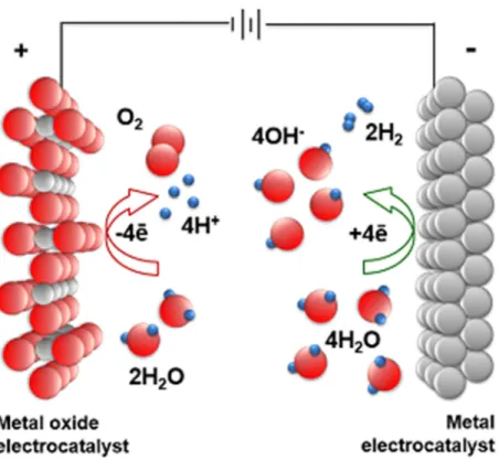
essential component of light-driven water splitting systems, which provides protons and electrons for the production of hydrogen. The overall water splitting reaction in alkaline electrolyte is as follow.
2H2O + 2e-àH2+ 2OH-△E0= - 0.41 V (1)
2OH-à1/2 O2(g) + 2H2O + 2e-△E0= + 0.82 V (2) 2H2O à2H2(g) + O2(g)
△G0= 237.2 kJ/m △E0= 1.23 V (3)
Two water molecules dissociate and hydrogen arises at the cathode by this reaction. At the anode, oxygen arises and a water molecule is generated at the same time. As a result, when a water molecule dissociates, another water molecule moves to the anode. The liquid electrolyte allows ions to be transported between the electrodes and is not consumed in the chemical reaction, but is periodically replenished depending on the losses in the system. The electron-transfer processes at electrocatalyst/electrolyte junctions produce losses due to the concentration and kinetic overpotential needed to drive the HER and the OER. The energy required for electrolysis is therefore conventionally compared at overpotential for achieve current density of 10 mA/cm2to account for these losses.
Figure 1-2 Oxygen and hydrogen evolution reaction (OER and HER) for overall water splitting.
three primary measures of efficiency are used, as follows.[3,5,7]
● Benchmark efficiency (suitable for mainstream reporting of stand-alone water splitting capability)
- Solar-to-hydrogen conversion efficiency (STH)
● Diagnostic efficiencies (to characterize and understand materials system/interface performance)
- Tafel slope - Overpotential
1-2-2-1. Solar-to-hydrogen conversion efficiency (STH)
STH efficiency is the most overarching of all efficiency metrics as it describe the overall efficiency of a PV-EC system exposed to broadband solar irradiance (e.g., Air Mass 1.5 Global illumination, 100 mW/cm2) under zero-bias conditions. Zero-bias means that there is no applied voltage between the working electrode and counter electrode, and all of the energy in the water splitting process is being supplied by sunlight. For standard STH efficiency can be expressed as chemical energy of the hydrogen produced divided by solar energy input from sunlight incident on the
from the rate of hydrogen production (mmol H2/s) multiplied by the change in Gibbs free energy per mole of H2 (△G0 = 237 kJ/mol, 25 oC).[7] In the denominator of the STH definition, the solar energy input from sunlight is incident illumination power density (Ptotal, in units of mW/cm2) multiplied by the illuminated electrode area (cm2).
STH=[ ( )* 1.23 (V) * nF
Ptotal cm2mW *Area (cm2)]AM 1.5G
1-3. Scope and objectives of the thesis
This thesis focuses on the develop technology for fabricating highly efficient solar to fuel system using the nanostructured non-noble metal based electrocatalysts. Hydrogen is considered as an ideal energy carrier to meet these challenges since it is clean, renewable, carbon-free, and has a high energy density. Electrochemical assisted by photovoltaic (PV-EC)
with multi-functions offers a lot of opportunities to develop high performance electrochemical water splitting. Even though metal oxides are promising candidate for electrochemical water splitting, they have their intrinsic limitations such as sluggish carrier transport, extraction and large electrical resistivity, and thus it is detrimental to electrochemical performance. Therefore, a variety of strategies have been introduced to address the aforementioned drawbacks of non-noble metal based electrocatalysts as water splitting electrodes for overall water splitting. Most of all, the anodic reaction will most likely involve oxidation of water. Due to the slow kinetics involving multi-electron and multi-proton transfers, water oxidation is particularly demanding and requires high overpotential. Thus, in this thesis, developing an efficient and practical anode system that can oxidize water to oxygen in a stable manner is introduced for the successful construction of high performance, commercially viable electrochemical cell.
Figure 1-6 shows suggesting ideas to improve PEC performance of metal oxides and final goal to approach practical field. The research presented in this thesis involves several engineering concept such as explore new composition, nanostructures, and PV-EC systems to access efficient hydrogen production efficiency and further expands the understanding and
Figure 1-3 Various strategies to enhance water splitting activities of non- noble metal based electrocatalysts.
1-4. Reference
[1] A. E. Outlook, US Department of Energy, United States Government Printing Office: Washington, DC, 2013.
[2] D. Kim, K. K. Sakimoto, D. Hong and P. Yang, Angew. Chem. Int. Ed., 2015, 54, 3259.
[3] C. Jiang, S. J. Moniz, A. Wang, T. Zhang and J. Tang, Chem. Soc. Rev., 2017, 46, 4645.
[4] H. L. Tuller, Materials for renewable and sustainable energy, 2017, 6, 3.
[5] M. G. Walter, E. L. Warren, J. R. McKone, S. W. Boettcher, Q. Mi, E. A.
Santori and N. S. Lewis, Chem. Rev., 2010, 110, 6446.
[6] H. M. Chen, C. K. Chen, R.-S. Liu, L. Zhang, J. Zhang and D. P.
Wilkinson, Chem. Soc. Rev., 2012, 41, 5654.
Chapter 2
Grain boundary as a dominant active sites for oxygen
evolution reaction in metal alloy electrocatalysts
2-1. Introduction
With the rapid increase of global temperature and depletion of fossil fuels, developing sustainable energy resources is crucial nowadays. Among the various renewable energy source generation approaches, water splitting has attracted increasing attention for clean energy generation and efficient energy storage. Electrochemical production of hydrogen from solar electricity is also an attractive option for generating energy in the form of hydrogen which could be used for electricity. Amidst many hydrogen generation techniques such as coal, wind, solar, and electrolysis, water splitting is a promising candidate that is environmentally friendly and highly efficient. However, it still remains a great challenge to develop sufficiently efficient electrocatalysts to generate hydrogen energy that is competitive with fossil fuels. Grain boundary could supply additional active sites that has potential to enhance overall water splitting properties in terms of overpotential and current density. This work may provide a cost-effective and simple way to develop the highly efficient hydrogen generation technique by control the surface grain boundary density.
2-1-1. Advantages of grain boundary at CO2reduction reaction
Grain boundary (GB) has a high potential to increase the activity of the materials, so it has attracted attention in many study. Especially in CO2
reduction reaction, grain boundary is promising era because it can extremely enhance the CO2reduction efficiency with equal CO2reduction catalysts. As reported in many articles, the grain boundary of materials at surface has strong CO binding sites than the sites on terraces or stepped surfaces. As a results, the grain boundary could alter the reaction step, especially the CO dimerization step. Similar to the contribution on CO2reduction reaction, the grain boundary also could enhance the water splitting properties, as properly controlled. In this regard, various grain-sized NiFe binary alloys with single FCC phase, from nanometer scale to 440 micrometer scale, are evaluated to reveal the correlation of grain boundary density and electrochemical water splitting efficiency.
2-2. Experimental method and characterization
2-2-1. Arc-melting synthesis of micrometer scale grain sized NiFe alloy for electrocatalysts
The samples were produced by arc melting method using metallurgical ingredients above 99.9% purity under Ti-gettered high-purity Argon atmosphere. The alloy button was re-melted more than five times to improve the compositional homogeneity. The NiFe binary alloys were then suction casted into a water-cooled copper mold with a rectangular cavity (= 12 mm width × 4 mm thickness × 50 mm length). The suction casted alloys were homogenized at 1050 °C for 24 h in an Ar atmosphere and eventually quenched in water. The homogenized samples underwent cold rolling to a total rolling reduction ratio of 70–85% followed by annealing above the recrystallization temperature in an Ar atmosphere followed by water quenching. Recrystallization annealing condition is 900 °C 3 min for 20 micrometer grain NiFe alloy and 1250 °C 24 h for 440 micrometer grain NiFe alloy, respectively. The bulk samples were mechanically ground into a
15 μm-thick ribbon, with SiC abrasive paper down to P4000.
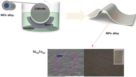
2-2-2. Pulsed electrodeposition for nanometer grain NiFe binary alloy
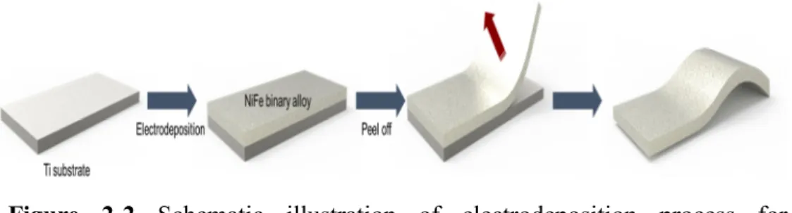
The electroforming of NiFe alloy was carried out in a three-electrode system with Ti foil (Alfa Aesar, annealed, 99.6%) as the working electrode, dimensionally stable anodes (DSA, Ti/IrO2) as a counter electrode, and Figure 2-1 Schematic illustration of fabrication process for various grain size NiFe binary alloy.
cleaned with acetone, isopropyl alcohol, and distilled water by ultrasonication. The surface of the Ti foil was covered with adhesive tape, except for the active area (1.5 cm × 3.5 cm). For the deposition of typical NiFe alloy, a Fe-Ni aqueous plating solution (400 ml) was prepared by dissolving 0.378 M (nickel sulfate hydrate (NiSO4∙6H2O, DAEJUNG), 0.122 M iron sulfate heptahydrate (FeSO4∙7H2O, DAEJUNG), 0.052 M boric acid (H3BO3, JUNSEI) as a buffer reagent, 1.3 mM sodium saccharin dihydrate (C7H4NNaO3S∙2H2O, DAEJUNG) as a stress reducer, and 0.082 M sodium chloride (NaCl, DAEJUNG) as a supporting reagent. To prevent the precipitation of iron species, 0.2 ml of hydrochloric acid (DAEJUNG) was added. For NiFe alloys with various compositions, the total amount of moles of Ni and Fe precursors were controlled to 0.5 M. Before electroforming, Ti foil was soaked for 5 min in diluted HCl to remove the residual oxide layer. The optimized current density of -40 mA/cm2 vs
2-2-3. Scanning Photoelectrochemical Microscopy (SPECM)
The direct observation of water splitting reaction at surface, especially grain boundary and grain, was conducted by scanning photoelectrochemical
Figure 2-2 Schematic illustration of electrodeposition process for nanometer scale grain size NiFe binary alloy
microscopy (SPECM).
2-2-4. Physical characterization
The morphologies of NiFe binary alloys were characterized by field emission scanning electron microscopy (MERLIN Compact, JEOL). Bright- field and high-resolution transmission electron microscopy (JEM-2100F, JEOL) with 200 kV field-emission images were obtained to investigate the microstructure of the NiFe alloys. X-ray diffraction (XRD) characterization was performed to confirm the crystalline phase of NiFe alloys. EBSD measurement was performed with a Hikari camera and the TSL OIM data- collection software. The EBSD scan step size was 75 nm and a tolerance angle of 5° was used for grain identification.
2-2-4. Electrochemical characterization
recorded using a computer-controlled multichannel electrochemical analyzer potentiostat (IVIUM STAT), which was used to simultaneously control the potential. EIS spectra were recorded using the same potentiostat in the preceding three-electrode configuration. A sinusoidal voltage perturbation with an amplitude of 10 mV and frequencies ranging from 350 kHz to 1 Hz was superimposed onto the bias voltage to gather the EIS data. The EIS data were fit to the equivalent circuits. Electrochemical impedance spectroscopy (EIS) was conducted by applying 0.5 V vs. Ag/AgCl. The measured spectra were fitted by using the ZSimpWin software.
2-3. Results and discussion
2-3-1. Fabrication of micrometer grain-sized NiFe binary alloys using the arc-melting process
To fabricate NiFe binary alloys for intended phase and composition, the Figure 2-4 (a), (b) is the high resolution TEM images of 20μm grain and 440μm grain, respectively. (c) is X-ray diffraction patterns of different samples. (d), (e) show the EBSD images of 20μm grain and 440μm grain.
NiFe binary alloys (grain size from 20 micrometer and 440 micrometer) were equally have single FCC phase NiFe binary alloys and randomly distributed over the surface, as shown in figure 2-4 (d) and 2-4 (e). The non- poly crystalline structure like X-ray pattern of 440 micrometer gran sized NiFe binary alloy is due to the smaller beam size of X-ray source.
Before compare the grain size contribution to water splitting properties, optimal ratio between Nni and Fe is also measured. NiFe binary alloy with 60 at% Fe shows maximum water splitting properties, as reported.
2-3-2. Electrochemical water splitting properties of micrometer
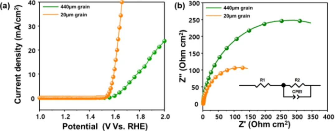
Figure 2-5 (a) Linear sweep voltammograms measured in 1 M NaOH at a scan rate of 10 mV/s for micrometer scale grain sized NiFe binary alloys.
(b) EIS measurement of micrometer scale grain sized NiFe binary alloy at 1.5V vs. RHE.
grain size NiFe binary alloys fabricated by arc-melting process
To reveal the contribution of surface grain boundary density to overall oxygen evolution reaction, I employed different grain sized NiFe binary alloys with same composition, morphology, and phase, from 20 micrometer to 440 micrometer grain size. Because the grain size different 20 fold, surface grain boundary density is expected to different about 20 fold. For compare the grain boundary density to water splitting properties, linear sweep voltammograms and EIS measurement is conducted at 1M NaOH solution, using three electrode system.
As expected before, the NiFe binary alloys with 20 micrometer sized grain shows noticeable superb oxygen evolution properties than the NiFe binary alloys with 440 micrometer sized grain. Overpotential for achieve current density of 10 mA/cm2is differ from 552 mV to 370 mV. The EIS measurement of the micrometer scale grain sized NiFe binary alloys was
charge transport efficiency since the EIS plot of 440 micrometer grain sized NiFe binary alloys nanorods indicates large semicircle compared to 20 micrometer grain sized NiFe binary alloy. The linear sweep voltammetry (LSV) curves of our NiFe binary alloys shows dramatic change between small grain and large grain, but the overpotential is still larger than those of reported NiFe binary alloys for achieve current density of 10 mA/cm2. Thus, further improvements are needed to generate higher photocurrents.
2-3-3. Electrochemical water splitting properties of nanometer grain size NiFe binary alloys fabricated by pulsed
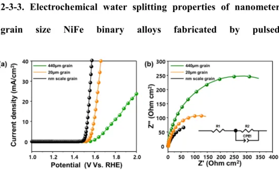
Figure 2-6 (a) Linear sweep voltammograms measured in 1 M NaOH at a scan rate of 10 mV/s for all samples. (b) EIS measurement of NiFe binary alloy at 1.5V vs. RHE for all samples.
electrodeposition
For the extreme compare of grain boundary density, we prepare the nanometer scale grain sized NiFe binary alloys with same composition, phase. Although the direct comparison of NiFe binary alloys synthesized by arc-melting process and electrodeposition process is difficult, at least the slight relation between grain boundary density and oxygen evolution reaction activities can be revealed because the prepared samples are has same composition and same phase, single FCC. The oxygen evolution reaction properties with vary grain size NiFe binary alloys are shown in figure 2-6 (a). As expected above, nanometer scale grain sized NiFe binary alloys show superb oxygen evolution properties than the micrometer scale
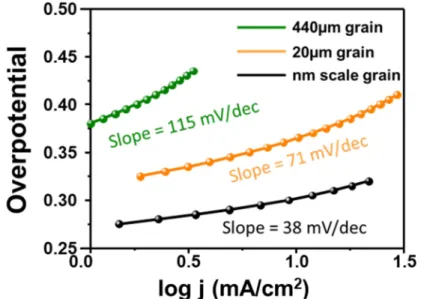
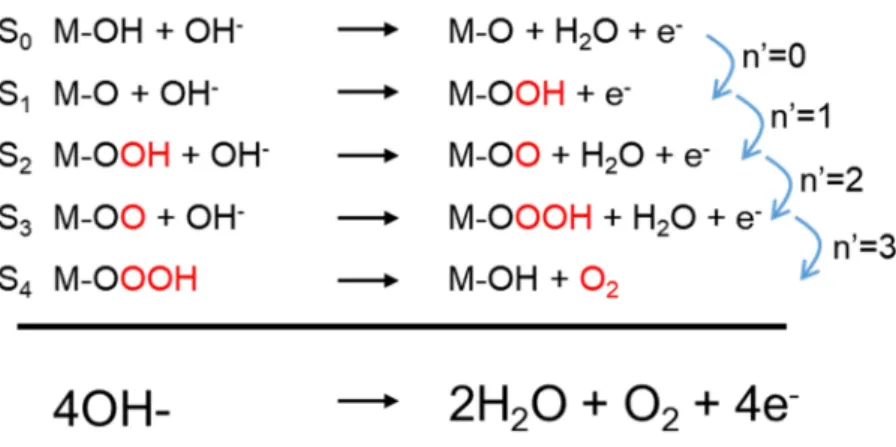
calculate the number of single elctron transfer steps prior to the reaction determining step, n’. As calculated from figure 2-7, the number of electro transfer steps prior to the reaction determining step (n’) is changed from 0.01 for 440 micrometer grain, 0.33 for 20 micrometer grain to 1.05 for nanometer scale grain sized NiFe binary alloys. In typical charge transfer steps reported for metal hydroxide, the rate determining steps is changed
from S0to S1, indicate that the surface grain boundary density changes bring reaction mechanism change. Furthermore, the reaction mechanism at the grain and grain boundary is differ each other, due to the different OH binding energy at the surface.
Figure 2-7 Tafel plot of various grain sized NiFe binary alloys.
Figure 2-8 Charge transfer steps of typical metal hydroxide.
1.2 V Vs. RHE, scan rate from 10 mV to 200mV, the double layer
capacitance is remarkably different for NiFe binary samples. As using same theoretical double layer capacitance as a constant, the active surface area of NiFe binary alloys is 25 fold different, as shown in figure 2-9. It also explain the grain boundary act as active sites at the surface, contribute to enhance the overall water splitting properties.
For direct observation of oxygen evolution activity change of grain and grain boundary, scanning photoelectrochemical microscopy (SPECM) Figure 2-9 Electrochemical surface area measurement using double layer capacitance.
V to 2 V Vs. RHE, the oxygen evolution reaction is mainly occurred at the grain boundary (figure 2-10). The NiFe binary alloys with nanometer scale grain sized show random-evolution of oxygen bubble, because of large surface grain boundary density. The NiFe binary alloys with 440 micrometer scale grain sized show grain boundary preferred oxygen bubble evolution unlike the nanometer scale grain sized NiFe binary alloy. (Figure 2-10)
Those results support the same phenomenon, a critical role of grain boundary density on the oxygen evolution reaction activities. I would like to stress the importance of the optimized composition and conformal surface grain boundary density of metal alloy electrocatalysts to enhance the overall electrochemical water splitting efficiency. Excessive Fe contents of NiFe alloys can deter the effective oxidation of Ni and water oxidation reaction, and deficient Fe contents of NiFe binary alloys has less active sites for efficient water oxidation reaction. Indeed, as grain boundary act as active sites and supply different reaction mechanism at the surface, extremely increased surface grain boundary density with same composition, morphology, and phase have largely enhanced overall water splitting properties than others. In light of the significant improvement in electrochemical water splitting properties, characterization, the optimized composition and grain sized NiFe binary alloy electrocatalyst showed the best performance without additional doping or co-catalysts, and thus may enable enhancement of electrochemical water oxidation.
2-4. Conclusion
I studied various grain sized NiFe binary alloys with same composition,
density and water splitting reaction activities. It is clear that the grain boundary is more active than the grain and the charge transfer steps are differ between the grain boundary and grain. The optimized atomic ration of NiFe binary alloys with the maximization of surface grain boundary efficiency showed a markedly enhanced current density and reduced overpotential for oxygen evolution reaction. Our approach can be applied to various metal alloy electrocatalysts, in which the OER activity of the oxygen evolution catalysts can be enhanced using an additional dopant or catalyst.
2-5. References
[1] Middleton, R. S.; Keating, G. N.; Stauffer, P. H.; Jordan, A. B.;
Viswanathan, H. S.; Kang, Q. J.; Carey, J. W.; Mulkey, M. L.; Sullivan, E. J.;
Chu, S. P.; Esposito, R.; Meckel, T. A., The cross-scale science of CO2 capture and storage: from pore scale to regional scale. Energy &
Environmental Science 2012, 5 (6).
[2] Xiao, Z.; Wang, D.; Dong, Q.; Wang, Q.; Wei, W.; Dai, J.; Zeng, X.;
Huang, J., Unraveling the hidden function of a stabilizer in a precursor in improving hybrid perovskite film morphology for high efficiency solar cells.
Energy & Environmental Science 2016, 9 (3), 867-872.
[3] Lim, J.; Hörantner, M. T.; Sakai, N.; Ball, J. M.; Mahesh, S.; Noel, N. K.;
Lin, Y.-H.; Patel, J. B.; McMeekin, D. P.; Johnston, M. B.; Wenger, B.;
halide perovskite thin films. Energy & Environmental Science 2019, 12 (1), 169-176.
[4] Oh, H. S.; Kim, S. J.; Odbadrakh, K.; Ryu, W. H.; Yoon, K. N.; Mu, S.;
Kormann, F.; Ikeda, Y.; Tasan, C. C.; Raabe, D.; Egami, T.; Park, E. S., Engineering atomic-level complexity in high-entropy and complex concentrated alloys. Nat Commun 2019, 10 (1), 2090.
[5] Dai, W.; Lu, T.; Pan, Y., Novel and promising electrocatalyst for oxygen evolution reaction based on MnFeCoNi high entropy alloy. Journal of Power Sources 2019, 430, 104-111.
[6] Lu, Q.; Hutchings, G. S.; Yu, W.; Zhou, Y.; Forest, R. V.; Tao, R.; Rosen, J.; Yonemoto, B. T.; Cao, Z.; Zheng, H.; Xiao, J. Q.; Jiao, F.; Chen, J. G., Highly porous non-precious bimetallic electrocatalysts for efficient hydrogen evolution. Nat Commun 2015, 6, 6567.
[9] Batchelor, T. A. A.; Pedersen, J. K.; Winther, S. H.; Castelli, I. E.;
Jacobsen, K. W.; Rossmeisl, J., High-Entropy Alloys as a Discovery Platform for Electrocatalysis. Joule 2019, 3 (3), 834-845.
[10] Wang, S.; Xin, H., Predicting Catalytic Activity of High-Entropy Alloys for Electrocatalysis. Chem 2019, 5 (3), 502-504.
[11] Xia, C.; Jiang, Q.; Zhao, C.; Hedhili, M. N.; Alshareef, H. N., Selenide- Based Electrocatalysts and Scaffolds for Water Oxidation Applications. Adv Mater 2016, 28 (1), 77-85.
[12] Chua, C. S.; Ansovini, D.; Lee, C. J.; Teng, Y. T.; Ong, L. T.; Chi, D.;
Hor, T. S.; Raja, R.; Lim, Y. F., The effect of crystallinity on photocatalytic performance of Co3O4 water-splitting cocatalysts. Phys Chem Chem Phys 2016, 18 (7), 5172-8.
[13] Warren, S. C.; Voitchovsky, K.; Dotan, H.; Leroy, C. M.; Cornuz, M.;
Stellacci, F.; Hebert, C.; Rothschild, A.; Gratzel, M., Identifying champion nanostructures for solar water-splitting. Nat Mater 2013, 12 (9), 842-9.
[14] Yan, Y.; Jiang, C. S.; Noufi, R.; Wei, S. H.; Moutinho, H. R.; Al-Jassim, M. M., Electrically benign behavior of grain boundaries in polycrystalline CuInSe2 films. Phys Rev Lett 2007, 99 (23), 235504.
CO2 electroreduction activity. J Am Chem Soc 2015, 137 (14), 4606-9.
[16] Feng, X.; Jiang, K.; Fan, S.; Kanan, M. W., A Direct Grain-Boundary- Activity Correlation for CO Electroreduction on Cu Nanoparticles. ACS Cent Sci 2016, 2 (3), 169-74.
[17] Cai, Q.; Hong, W.; Jian, C.; Li, J.; Liu, W., Insulator Layer Engineering toward Stable Si Photoanode for Efficient Water Oxidation. ACS Catalysis 2018, 8 (10), 9238-9244.
[18] Zankowski, S. P.; Vereecken, P. M., Electrochemical Determination of Porosity and Surface Area of Thin Films of Interconnected Nickel Nanowires. Journal of The Electrochemical Society 2019, 166 (6), D227- D235.
[19] Wang, Y.; Liu, D.; Liu, Z.; Xie, C.; Huo, J.; Wang, S., Porous cobalt- iron nitride nanowires as excellent bifunctional electrocatalysts for overall
Graphene Films. Adv Mater 2019, 31 (9), e1800996.
[22] Cui, X.; Zhang, B.; Zeng, C.; Guo, S., Electrocatalytic activity of high- entropy alloys toward oxygen evolution reaction. MRS Communications 2018, 8 (03), 1230-1235.
Chapter 3
Solution processed electrocatalysts with nanometer scale
grain using earth abundant elements for overall water
splitting reaction
3-1. Introduction
With the rapid development of industry and population growth, demands for energy are increasing, and the limits of fossil fuels are being revealed. The centuries-old use of fossil fuels has left behind an energy crisis and severe environmental pollution. Thus, the development of sustainable energy resources has become crucial.1-6 Compared with other renewable energy
generation techniques, water splitting using photovoltaic–driven electrolysis (PV-EC) is a promising candidate that is environmentally friendly and highly efficient. However, it still remains a great challenge to develop electrocatalysts and photovoltaic devices which generate hydrogen energy with efficiency that is competitive with fossil fuels.9-10
Currently, the most efficient catalysts for water splitting are noble-metal catalysts such as Pt-group metals11 and Ru- and Ir-based compounds.12 Unfortunately, the scarcity and high cost of noble metals seriously impede their large-scale applications in electrocatalytic water splitting. Therefore, more abundant elements are being considered for the role of catalysis. The majority of nonprecious oxygen evolution reaction (OER) catalysts are metal oxides and (oxy)hydroxides.13-14 In the past few decades, Ni has emerged as an important nonnoble metal due to its catalytic power for water splitting, with Ni-based compounds being intensively studied as efficient OER15-16 and HER17-20 catalysts. Among the various types of Ni-based materials, (oxy)hydroxide metal alloys with Fe have attracted much attention due to their special redox characteristics and good accessibility for the reaction species.21To date, the synthesis of NiFe (oxy)hydroxide has relied on hydrothermal,22 pulsed laser ablation (PLAL).23 Hydrothermal
typically involves harsh chemical conditions such as a low or high pH, which leads to substrate damage. Although the pulsed laser ablation (PLAL) method has been a simple synthetic route for preparing fine films, the use of vacuum-based equipment is not applicable to industrial processes. For these reasons, direct synthesis from NiFe alloy to NiFe (oxy)hydroxide using anodization can be a simple, economical and clean process for successfully synthesizing uniform films. In addition, the anodization method can be used to simply control the area, surface structure and surface chemistry of the films to serve a desired purpose. Bimetallic electrocatalysts based on Ni have also attracted increasing attention as a reliable approach to enhance electrocatalytic activity for the HER. Meanwhile, inspired by the abundant use of the element Ni in nature, various Ni-based catalysts have been designed to catalyze the conversion of H2O into H2 in commercial alkaline electrolyzers. Among these, Ni–Mo alloys are well-known nonprecious- metal electrocatalysts for hydrogen production in alkaline electrolytes
using metal foam, we adopt a NiFe alloy foil as a substrate because well- controlled NiFe alloy shows a superior water splitting performance compared to pure nickel or iron metal. To optimize the catalytic activity, each catalyst was deposited or synthesized in a nanostructured form, and the surface valences were carefully controlled during the synthesis process.
Directly synthesized NiFe (oxy)hydroxide showed outstanding OER properties with a low overpotential (250 mV at the OER at 10mA cm-2in a 1 M NaOH aqueous solution). This is the lowest value among previously reported NiFe (oxy)hydroxide films. Experimental investigations reveal that the synthesized NiFe (oxy)hydroxide behaves as a highly active center and manifests OER kinetics. Electrodeposited NiMo films also exhibit high water splitting properties with a low overpotential (100 mV at 10 mA cm-2) and low Tafel slope (22.2 mV per decade) in a 1 M NaOH aqueous solution, which are comparable to those of a Pt plate (10 mA cm-2 overpotential: 130 mV; Tafel slope: 19.1 mV per decade).27 With these highly efficient electrocatalysts in hand, the next step was to combine them with a solar cell for the purpose of directly converting solar energy into the form of an energy source, namely, hydrogen. Our photovoltaic-electrochemical (PV- EC) cells connected by metal wires were found to exhibit a solar-to- hydrogen efficiency of 17.52% under simulated AM 1.5G solar irradiation
(100 mW cm−2), which is superb compared to reported articles, as many advantages like;
1. Facile and low cost synthesis
Metal (oxy)hydroxide is regarded as a promising water splitting catalysts, because of the unique physical and chemical properties. Specially Ni based (oxy)hydroxides have been widely investigated with superior activities comparable to the noble metal based catalysts like platinum, ruthenium oxide or iridium oxide. To date, the synthesis of NiFe (oxy)hydroxide has mainly relied on hydrothermal or pulsed laser ablation, which require toxic chemicals and high-cost process. For this reasons, existing synthesizing methods has limitation in practical industrial application. Here in this work, we overcome the current problems by applying fully solution- based processes (anodization for the oxygen evolution catalyst and electrodeposition for the hydrogen evolution catalyst) for simple,
Highly active catalysts for the water splitting are required for the efficient hydrogen production. To achieve superior activities, each catalyst should have fast charge transportation rate and large active surface area. By using anodization and electrodeposition, we could achieve optimized conductivity and surface morphology that maximizing the water splitting properties of catalysts. NiFe (oxy)hydroxide synthesized by an anodization method for the OER catalyst shows an overpotential of 250 mV at 10 mA cm-2, which is dramatically smaller than that of bare NiFe alloy with an overpotential of 520 mV at 10 mA cm-2. Electrodeposited NiMo films for the HER catalyst also exhibit a small overpotential of 100 mV at 10 mA cm-2 compared with that of bare NiFe alloy (550 mV at 10 mA cm-2). Two-electrode cell also shows outstanding performance than as reported many articles, an extremely small overpotential of 390 mV at 10 mA cm-2.
3. Remarkable solar-to-hydrogen efficiency
In terms of practical performances, two electrode cell combining with photovoltaic devices could be a fine way to evaluate the efficiency of water splitting catalysts. In this work, water splitting experiments using solar energy were performed with monolithic perovskite/Si tandem cells. These tandem cells exhibit a very suitable open-circuit voltage for the water
collected near 1.5 V. Using the tandem cell exhibited a high PCE of 23.1%, operating current density of the combined system achieve a value of 14.24 mA cm−2. Taking ηF = 100% and Jsc= 14.2 mA cm-2, the STH efficiency was determined to be 17.52%. Compared with other recently reported PV-EC systems, our system is comparable to state-of-the-art solar water splitting systems in terms of the solar-to-hydrogen efficiency (STH) and the solar-to- hydrogen efficiency per photocurrent-to-charge efficiency (STH/PCE).
3-2. Experimental method and characterization
3-2-1. Synthesize of NiFe alloyFigure 3-1 and 3-2 shows an illustration of our synthesizing methods for forming NiFe (oxy)hydroxide and Ni4Mo films on the as-prepared NiFe alloy used in this study. All of the process to synthesize electrocatalysts used in this work were based on fully solution method, facile and low cost process. Solution process also has many advantages like easy control of the
surface morphology, flexibility and scale of the materials. NiFe alloy used in this work were synthesized by roll-to-roll process.
Figure 3-1 Sketch diagram of electroforming process to make an NiFe alloy foil. Cathode electrode was rolling with continuous supplied bath solution, NiFe alloy foil are deposited on the other side of electrode coil.
3-2-2. Synthesize of NiFe (oxy)hydroxide and NiMo
Figure 3-2 Illustrated sketch of our synthesis procedure for forming a water splitting cell. The cathode material was deposited onto the NiFe alloy by using an electrodeposition method, and the anode material was obtained simply by anodizing the NiFe alloy. The key idea of our method is the direct anodization of the metal alloy substrate for the synthesis of more efficient electrodes with long-term stability.
used as a working electrode and platinum foil used as a counter electrode at room temperature. All of the samples were formed by simply anodizing the NiFe alloy in ethylene glycol containing 0.3 wt % NH4F solution and 3 vol % water at a constant voltage. The NiFe(oxy)hydroxide films on the NiFe alloy show a slightly yellowish nanoporous structure after anodization.
After anodization, the samples were immediately rinsed with DI water and subsequently dried in air. Ni4Mo alloy was synthesized by a direct electrodeposition method. Briefly, the electrodeposition process was performed on the as-prepared NiFe foil in an electrolyte containing 0.017 M nickel sulfate, 0.016 M sodium citrate, 0.00036 M ammonium molybdate and 0.285 M sodium chloride at a cathodic voltage of 1.2 V for 60 min. The pH of this electrolyte was adjusted at 8.5 by ammonium hydroxide, and the temperature was elevated to 50 °C with continuous stirring. After electrodeposition, the NiFe foil was covered by a gray metal film.
3-2-3. Fabrication of the monolithic perovskite/Si solar cells
Perovskite/Si tandem solar cells was synthesized simply with the previous paper.46 Both sides of 250-μm-thick n-type phosphor-doped Si wafers prepared by a floating zone technique were polished and sequentially cleaned using an RCA cleaning process. The Si-substrates had only a back-
solution to eliminate contaminants, the substrates were cleaned with deionized water. Then, 10–20-nm-thick-doped amorphous Si thin films were deposited on both sides of the Si substrate using a plasma-enhanced chemical vapor deposition reactor operating at radio frequency (RF 13.56 MHz). To dope the a-Si:H, hydrogen-diluted PH3and B2H6gases were used as sources. As a recombination layer, a 20-nm-thick ITO layer was deposited using a radio-frequency (RF) sputtering method with a power of 50 W under a working pressure of 2 mTorr at room temperature. For the deposition of NiO as a hole extraction layer, 0.1 M nickel(Ⅱ) acetate tetrahydrate solution was spin-coated onto Si-cells and annealed at 220 °C for 1 h. The substrates were moved to a N2-filled glove box (O2 and H2O less than 1 ppm) for the deposition of perovskite films. A total of 100 μL of the perovskite solution containing 1.275 mmol of PbI2 (Alfa Aesar, 99.9985%), methylammonium iodide (Greatcellsolar) and 0.225 mmol of
mg mL–1 in 1,2-dichlorobenzene) and a ZnO nanoparticle ink (Sigma- Aldrich) were sequentially spin-coated onto the perovskite films as electron- extraction layers. A 150-nm-thick layer of ITO film was deposited by the same conditions with a recombination layer, and a 150-nm-thick layer of Ag metal electrode deposited by thermal evaporation at a deposition rate of 1.5 Å/s.
3-2-3. Physical characterization
The XRD data were acquired using a BRUKER MILLER Co., D8- Advance diffractometer with Cu Kα radiation (λ = 1.5406 Å) operating at 45 kV and 200 mA at a scanning rate of 0.06° sec–1. The surface and cross- sectional images were obtained from a field emission scanning electron microscope (ZEISS, MERLIN Compact) and transmission electron microscope (TEM) JEOL JEM 3000F. X-ray photoelectron spectroscopy (XPS) measurements were carried out using KRATOS AXIS-His and a monochromated Al-Kα (hν = 1486.58 eV) X-ray source to determine the composition of the synthesized rod. The high-resolution spectra of the Ni 2p, Fe 2p, Mo 3d, O1s, and C1s core levels were identified using a pass energy of 100 eV through a 0.4 mm analyzer silt width. Each high-resolution scan
time of 157 ms per step. The J–V measurements were performed using a potentiostat (CHI 608C, CH Instruments) and a solar simulator (Peccell Technologies, AAA graded) under AM 1.5G illumination conditions. The solar simulator was used after calibration with a reference cell (PV Measurements). The aperture size defined by the metal mask was 0.1875 cm2.
3-2-4. Electrochemical characterization
: All water splitting performance measurements except for the two- electrode system were carried out in a three-electrode configuration consisting of the as-prepared working electrode, calomel reference electrode, and a Pt wire as a counter electrode with 1 M NaOH electrolyte solution, with the pH of the electrolyte considered to be 14. All potentials were
using a computer-controlled multichannel electrochemical analyzer potentiostat (IVIUM STAT), which was used to simultaneously control the potential. EIS spectra were recorded using the same potentiostat in the preceding three-electrode configuration. A sinusoidal voltage perturbation with an amplitude of 10 mV and frequencies ranging from 350 kHz to 1 Hz was superimposed onto the bias voltage to gather the EIS data. The EIS data were fit to the equivalent circuits. Faradaic efficiency and hydrogen/oxygen evolution rates were measured by using gas chromatography (GC) at a constant current density of approximately 10 mA cm-2.
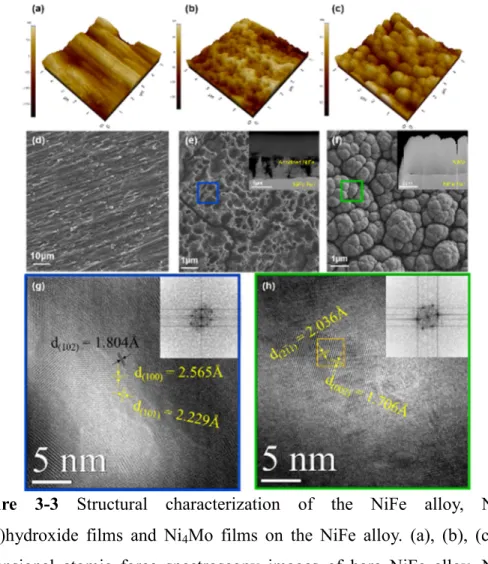
3-3-1. Structure characterization of the NiFe (oxy)hydroxide and
Figure 3-3 Structural characterization of the NiFe alloy, NiFe
The structure and morphology of NiFe (oxy)hydroxide and Ni4Mo were characterized with a number of techniques. Three-dimensional AFM images clearly showed a microporous surface for the NiFe (oxy)hydroxide (Figure 3-3 b) and nanostructured Ni4Mo film (Figure 3-3 c) compared to the NiFe alloy (Figure 3-3 a). The morphologies of NiFe (oxy)hydroxide and Ni4Mo were examined by scanning electron microscopy (SEM) as shown in Figure 2d-2f. The anodization of NiFe alloy effectively leads to formation of microporous NiFe (oxy)hydroxide films with pore size in range of 0.5 – 1.0 µm, as shown in Figure 3-3 c. NiFe (oxy)hydroxide films with extensive, numerous pores can be acted as an active surface for water splitting reactions and contributed to enhancing the OER performance. Cross section image (inset of Figure 3-3 e) shows the thicknesses of the NiFe (oxy)hydroxide films to be approximately 2 µm. The Ni4Mo film deposited on the NiFe alloy (Figure 3-3 f) showed an isolated hemispherical structure with abundant protrusions, which is possible to provide enlarged active areas during the HER. The wide, open spaces between adjacent nanostructures and the coarse surface allowed fast ion diffusion and enlarged the contact area with electrolyte, which were both beneficial for improving the HER performance. The crystalline structure of the NiFe alloy, NiFe (oxy)hydroxide and Ni Mo films deposited on the NiFe alloy were
characterized by X-ray diffraction (XRD). The NiFe alloy deposited by roll- to-roll process at room temperature consists of a mixture of fcc and bcc phases, as evidenced from the X-ray diffraction (XRD) pattern, which shows fcc (111) and bcc (110) peaks with the strongest intensities at 43.7°
and 44.7°. The NiFe (oxy)hydroxide shows apparent NiFe (oxy)hydroxide X-ray diffraction peaks compared to the bare NiFe alloy, but the electrodeposited Ni4Mo films was not shows marked X-ray diffraction patterns, due to the intensify high XRD peak of NiFe alloy (Supplementary Figure S3).25 High-resolution transmission electron microscopy (HRTEM) was carried out to further analyze the phase and structure of NiFe (oxy)hydroxide (Figure 3-3 g) and Ni4Mo films (Figure 3-3 h). The smudgy selected area diffraction (SAED) pattern (inset of Figure 3-3 g) is due to the low crystallinity of the anodizing method; however, the lattice spacing clearly showed a polycrystal phase for Ni(OH)2 and NiFe (oxy)hydroxide.
Figure 2g shows a lattice spacing of 0.1804 nm for the nanostructure
that the electrodeposited films are suitably matched to Ni4Mo (JCPDS:007- 0562 with lattice spacing of 0.2036 nm and 0.1706 nm corresponding to the (211) and (002) planes, respectively. Diverse analysis equally concluded that NiFe hydroxide/NiFe oxy(hydroxide) and Ni4Mo films were successfully synthesized by the anodization method and electrodeposition, respectively.
Figure 3-4 XRD characteristics of the NiFe (oxy)hydroxide films and electrodeposited NiMo films.
3-3-2. Electrocatalytic oxygen and hydrogen evolution reaction
Figure 3-5 Electrochemical performance of different catalyst electrodes as characterized by linear sweep voltammetry in 1 M NaOH aqueous
In order to understand how the structure and phase affect the water splitting properties, we evaluate the electrocatalytic activities of the electrocatalysts by three-electrode system in a 1 M NaOH aqueous solution using a 3 M Ag/AgCl electrode and a platinum plate as the reference and counter electrodes, respectively. All potentials were referenced to the reversible hydrogen electrode (RHE), and the ohmic potential drop loss from the electrolyte resistance was subtracted. At first, a pure nickel foam was tested to compare the OER performance of the bare NiFe alloy. For the optimized pore size and conductivity of films, various anodizing conditions were tested. As revealed in Figure, the NiFe (oxy)hydroxide film anodized at the potential of 80V exhibited the highest OER activity, with a lowest overpotential at current density 10mA cm–2. As displayed in Figure 3a, the NiFe alloy showed a superior OER performance to the nickel foam due to the disparity in active surface area for water splitting reaction. The active surface area is one of the dominant factors that directly influences the activity of the electrocatalyst. Thus, a synergetic effect between Ni and Fe can not only offset the surface area shortage but also achieve a better water splitting performance for the NiFe alloy than the Ni foam at the OER. The OER performance of NiFe (oxy)hydroxide films (overpotential of 250 mV at a current density of 10 mA cm–2) is considerably enhanced compared to
the bare NiFe alloy (380 mV) and nickel foam (520 mV). Cyclic voltammetry curves (inset of Figure 3a) show a noticeable peak change between the NiFe alloy and NiFe (oxy)hydroxide. The green reduction peak in the red circle, as shown in Figure 3a represents a phase change from NiO(OH) to Ni(OH)2.26 As shown in the cyclic voltammetry curves, the NiFe (oxy)hydroxide films has a high rate of Ni3+ compared to the bare NiFe alloy, it is a crucial evidence that can demonstrate phase change from NiFe alloy to NiFe (oxy)hydroxide films after anodization. Usually, NiFe (oxy)hydroxide and metal (oxy)hydroxide electrocatalysts show superior water splitting properties to metal oxide or pure metal electrocatalysts due to their special redox characteristics and good accessibility for the reaction species,27-30 which can be the main reason for the enhanced OER properties of the NiFe (oxy)hydroxide films. The superior OER performance of the NiFe (oxy)hydroxide films was also confirmed by its smaller Tafel slopes as
–1
synthesizing conditions. As revealed in Figure S6, the NiMo alloy electrodeposited at the temperature of 60 degree, voltage of 2.5 V, deposition time of 1 hour exhibited the highest HER activity. For an objective comparison, a Ni foam and a Pt plate were also prepared. Unlike the OER, the bare NiFe alloy shows an inferior HER performance to the nickel foam. To drive overall water splitting system, HER performance should be improved, thus a Ni4Mo film was deposited onto the NiFe alloy, as a HER catalyst. The electrocatalytic performance of the Ni4Mo film for the HER was tested in 1 M NaOH. At a current density of 10 mA cm–2, the Ni4Mo film exhibits the smallest overpotential of 100 mV compared to the other samples, including the Ni foam (370 mV) and bare NiFe alloy, which is even better than that obtained for the pure Pt (130 mV) electrode. Figure 3d displays the Tafel plots for the corresponding polarization curves, which provide profound insights into the fundamental HER kinetic mechanisms occurring on the surfaces of the electrocatalysts. As a result of the low energy barrier (0.44 eV on Pt) for the Volmer step, the kinetic rate-limiting step for the Pt catalyst is the Tafel process, with the theoretical Tafel slope being 30 mV per decade. Remarkably, the Tafel slope for the Ni4Mo film was as low as 20 mV per decade, which is far lower than the values of 165 mV per decade and 168.2 mV per decade obtained for the Ni foam and
bare NiFe, respectively, and is highly comparable to that of the Pt-based catalyst. This result indicates that the electrocatalytic HER kinetics on the Ni4Mo electrocatalyst were determined by the Tafel step rather than a coupled Volmer–Tafel or Volmer–Heyrovsky process. In other words, the prior Volmer step was significantly accelerated. Additionally, except for the excellent water electrolysis properties, both OER and HER electrodes also exhibits a high stability during 200 cycle CV tests (Supplementary Figure S7), almost same after 200 cycles. This catalysts were shown superior water splitting activity than other reported non-noble metal based electrocatalysts, even comparable to that of the noble metal based catalysts like Platinum or Iridium oxide. (Supplementary Figure S8). To test the overall water splitting, a two-electrode cell was constructed by using NiFe (oxy)hydroxide as the anode and a NiMo alloy as the cathode. A photograph (Figure 4b) and corresponding movie (supplementary Movie 1) reveal that at an applied cell
configuration.31Even more, efficient water electrolysis can be powered by a single-cell 1.5 V AAA battery, (Figure 4) and superior that of as reported electrolysis cells.32 Supplementary movies showing hydrogen bubbles was vigorously occurred by 1.5 V AAA battery. This results indicate that our NiFe (oxy)hydroxide/Ni4Mo water splitting electrode has good possibility for practical applications.
Figure 3-6 2 electrode water splitting properties combining with a conventional 1.5 V battery. (a) Current density and (b) NiFe (oxy)hydroxide/NiMo water splitting system driven by an ~1.5 V AAA battery.