• 검색 결과가 없습니다.

TiO<sub>2</sub>@carbon Core-Shell Nanostructure Electrodes for Improved Electrochemical Properties in Alkaline Solution

N/A
N/A
Protected

Academic year: 2021

Share "TiO<sub>2</sub>@carbon Core-Shell Nanostructure Electrodes for Improved Electrochemical Properties in Alkaline Solution"

Copied!
5
0
0

로드 중.... (전체 텍스트 보기)

전체 글

(1)

http://dx.doi.org/10.5229/JECST.2012.15.2.90

− 90 −

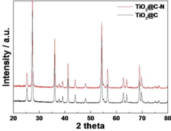
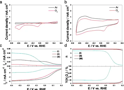
TiO 2 @carbon Core-Shell Nanostructure Electrodes for Improved Electrochemical Properties in Alkaline Solution

Do-Young Kim, Young-Woo Lee, Sang-Beom Han, A-Ra Ko, Hyun-Su Kim, Si-Jin Kim, Sang-Eun Oh

, and Kyung-Won Park*

Department of Chemical Engineering, Soongsil University, Seoul 156-743, Korea

Department of Biological Environment, Kangwon National University, Chuncheon, Gangwondo 200-701, South Korea

(Received Month day, 2012 : Accepted Month day, 2012)

Abstract : We report nanostructure electrodes with TiO

2

as a core and carbon as a shell (TiO

2

@C) for oxygen reduction in alkaline solution. The structure of core-shell electrodes is characterized by transmission electron microscopy, Raman spectroscopy, X-ray diffraction method, and X-ray photoelectron microscopy. The electrochemical properties of the TiO

2

@C electrodes are characterized using a potentiostat and compared with those of carbon supported Pt catalyst. In particular, the core-shell electrode with dominant pyridinic-N component exhibits an imporved electrocatalytic activity for oxygen reduction reaction in alkaline solution.

Keywords : Nanostructure materials, Core/shell, N-doping, Oxygen reduction reaction

1. Introduction

Oxygen reduction reaction (ORR) is one of the crucial characteristics in electrochemical energy conversion devices such as polymer electrolyte membrane fuel cells. The electrocatalytic ORR in alkaline fuel cells has attracted an intensive inter- est in alternative to Pt-based catalysts, although the ORRs in alkaline solutions are much faster than those in the acidic media.

1-6)

Furthermore, the search for a low-cost, stable and more active electrocatalysts for the ORR in alkaline medium is thus of great importance.

7,8)

Nitrogen-doped carbon materials have exhibited much higher ORR activity than undoped carbon materials.

9-13)

Nitrogen incorporation could chemi- cally present active sites into the carbon for the electrocatalytic reactions.

14-16)

The pyridinic nitro- gen doped the carbon substrate’s surface is shown to play important roles in the active sites for the ORR.

17-19)

In particular, TiO

2

has been proposed as a good candidate for an electrode due to its

chemical stability, cheapness, and nontoxicity.

20)

Herein, the nanostructure catalysts (TiO

2

@C) consisting of TiO

2

as a core and carbon as a shell were prepared for oxygen reduction reaction in alkaline solution. The particle size, crystal structure, and chem ical com ponents of the catalysts were characterized using transmission electron microscopy (TEM), Raman spectroscopy, X-ray diffraction (XRD) method and X-ray photoelectron spectroscopy (XPS). The electro- chemical properties of the catalysts were charac- terized using a potentiostat.

2. Experimental

2.1. Synthesis of catalysts

The nanostructure catalysts used TiO

2

(Degussa, P-25) as a starting material were prepared by m e a n s o f h e a t t r e a t m e n t u n d e r C H

4

g a s atmosphere. At first, the flow rate of N

2

gas was kept for 15 min to get rid of O

2

inside the tube. Under CH

4

flow rate of 100 mL min

−1

, the furnace was heated from room temperature to 700

o

C and then maintained for 5 h. After the

*E-mail: [email protected]

(2)

heat treatment for 5 h, the furnace was cooled d o wn to ro om te m p e r a tu re u nd e r m e th a ne atmosphere. To prepare nitrogen-doped TiO

2

@C catalysts, the FeTMPP (5,10,15,20-tetrakis(4- methoxyphenyl)-21H,23H-porphine iron(III) chloride, Aldrich) were dissolved in 99.7% acetic acid (2 ml, Aldrich) and acetone (90 ml, Aldrich) with continuous stirring for 1 h. After completely dissolving, the TiO

2

@C powders were added slowly into the solutions to form a homogeneous blended solution by adsorbing the FeTMPP on the TiO

2

@C. The solutions were completely evaporated and then dried at 50

o

C. The obtained powders were heated at 700

o

C for 5 h under N

2

flow rate of 50 mL min

−1

and then cooled down to room temperature under N

2

atmosphere.

2.2. Structural analysis

TEM analysis of the catalysts was performed on a field emission transmission electron micro- scope (Tecnai G2 F30 system). TEM samples were prepared by placing drops of catalyst sus- pension dispersed in ethanol on a carbon-coated copper grid. Raman spectra were recorded on Mirco-Raman spectrometer (Jobin Yvon HR800 UV) using an Ar ion laser with λ = 514.5 nm. XRD analysis was carried out using Rigaku X-ray diffractometer with Cu K

α

( λ = 0.15418 nm) source

with a Ni filter. The source was operated at 40 kV and 100 mA. The 2 θ angular scan from 20

o

to 60

o

was explored at a scan rate of 5

o

min

−1

. The resolution in the scans was kept at 0.02

o

. XPS (Thermo Scientific, K-Alpha) analysis was carried out with the Al K

α

X-ray source of 1486.8 eV at the chamber pressure below 1 × 10

−8

Torr and 200 W beam power. All high resolu- tion spectra were collected using a pass energy of 46.95 eV. The step size and time per step were chosen to be 0.025 eV and 100 ms, respec- tively. Both ends of the baseline were set suffi- ciently far so as not to distort the shape of spectra, including tails. Small variation of the range of the base line did not affect the rela- tive amount of fitted species (less than 1%). The C 1 s electron binding energy was referenced at 284.6 eV and a nonlinear least-squares curve-fitting program was employed with a Gaussian-Lorentzian production function.

2.3. Electrochemical analysis.

Electrochemical properties of the catalysts were measured in a three-electrode cell at 25

o

C using a potentiostat (CH Instrument, CHI 700 C). The Pt wire and Hg/HgO (in saturated NaOH) were used as a counter and reference electrode, respectively. The rotating ring disk electrode as a

Fig. 1. TEM images of TiO

2

@C (a,b) and TiO

2

@C-N (d,e). The insets indicate particle size histograms of the catalysts.

Raman spectra of TiO

2

@C (c) and TiO

2

@C-N (f).

(3)

working electrode was polished with 1, 0.3, and 0 .0 5 µm A l

2

O

3

p a s t e a n d t h e n w a s h e d i n deionized water. The catalyst inks were prepared by ultrasonically dispersing catalyst powders (20 mg) in NMP (N-Methyl-2-pyrrolidone) solution (15 µL) containing 5 wt% PVDF (Polyvinylidene fluoride). The catalyst ink was dropped 1.57 µL onto a rotating ring disk electrode. After drying in 50

o

C oven, the total loading (~500 µg cm

−2

) of all catalysts was identically deposited on the glassy carbon electrode. To compare electrochemical properties and ORR activity of the catalysts, characteristic curves were obtained between − 0.6 and 0 V in 0.1 M NaOH. The current-potential curves for the ORR were obtained using cyclic and linear sweep voltammetry in O

2

-saturated 0.1 M NaOH.

3. Results and discussion

Fig. 1 shows TEM images of the nanostructure catalysts for ORR. Compared to ~30 nm of commercial TiO

2

as a starting material, the average size of the TiO

2

heated at 700

o

C in CH

4

atmosphere is ~35 nm resulting from the increase of size due to heating process. Furthermore, it is observed that the undoped nanostructure catalyst (TiO

2

@C) consists of core and shell structure (Fig. 1(a)). As shown in HR-TEM image of Fig. 1(b), the d-spacing of the core structure corresponds to that of TiO

2

(0.327 nm) whereas the d-spacing of the shell structure corresponds to that of graphitic layer (0.342 nm), which is similar to d-spacing of 0.335 nm of typical

graphite. The measured thickness of the shell in the catalyst is ~2.0 nm. For N-doping in the TiO

2

@C, FeTMPP was deposited on carbon layers and then pyrolyzed under N

2

atmosphere (referred as TiO

2

@C-N). The TiO

2

@C-N (Fig. 1(d),(e)) exhibits core-shell nanostructure sim ilar to TiO

2

@C. The measured thickness of the shell in the TiO

2

@C-N is ~2.0 nm. As shown in HR- TEM images of Fig. 1(e), the core structures correspond to TiO

2

whereas the shell structures correspond to graphitic layer. The particle sizes of TiO

2

@C and TiO

2

@C-N are 32.85 and 38.53 nm, respectively (the insets of Fig. 1). The Raman spectra of the catalysts consist of two main peaks: a G-band at ~1590 cm

−1

resulting from the in-plane stretching vibration mode E

2g

of single crystal graphite and a D-band at ~1345 cm

−1

representing the disorder-induced characteristics (Fig. 1(c),(f)). The TiO

2

@C-N exhibits relatively l o w I

D

/ I

G

r a t i o , s u g g e s t i n g a n i m p r o v e d crystallinity of carbon despite the nitrogen doping as compared to the TiO

2

@C.

Typically, the commercial TiO

2

(Degussa, P-25) consists of dominant anatase and rutile phase. In contrast, the heated TiO

2

samples display mixed phases of anatase and dominant rutile, which means phase transformation of anatase into rutile phase (Fig. 2). It is observed that the anatase phase is transformed into the rutile phase at both heating temperatures. In general, it is known that the phase transformation from metastable anatase to stable rutile occurs at around 600

o

C . As shown in Fig. 3, the XPS peak of the catalyst contain three main portions of nitrogen to curve

Fig. 2 XRD patterns of TiO2@C and TiO2@C-N. Fig. 3. XPS N1s spectrum of TiO

2

@C-N.

(4)

fit in the N 1s spectrum. For the TiO

2

@C-N, the pyridinic-N and pyrrolic-N are assigned to the components at 398.1 and 400.3 eV, respectively, and the quaternary/graphitic-N is presented at 400.9 eV.

The ORR characteristics of the TiO

2

@C and TiO

2

@C-N in alkaline solution were evaluated using cyclic voltammetry (Fig. 4(a),(b)). The TiO

2

@C-N exhibits higher onset potential and higher current density than those of the TiO

2

@C indicating such an excellent ORR activity.

Furthermore, to characterize ORR performance and mechanism of these catalysts, rotating ring disk electrode analysis was carried out. The onset potential of the TiO

2

@C-N toward ORR in the polarization curves is significantly shifted to positive direction still lower than that of Pt/C, as compared with the TiO

2

@C (Fig. 4(c)). The disk current density (I

D

) of the TiO

2

@C-N is much larger than that of the TiO

2

@C, whereas the ring c u r r e n t d e n s i t y ( I

R

) o f t h e Ti O

2

@ C - N i s comparably smaller than that of TiO

2

@C. The plots of the number of exchanged electrons (n)

and the generation yield (%H

2

O

2

) of hydrogen peroxide during ORR versus electrode potentials are as shown in Fig. 4(d). The n exchanged by the TiO

2

@C-N toward ORR is determined to be approximately 4.0 as compared to 3.3~3.5 of the TiO

2

@C indicating that O

2

reduction reaction catalyzed on the TiO

2

@C-N is an apparent near four electron transfer process comparable to that of the Pt/C below − 0.1 V. For the Pt/C, no signficant H

2

O

2

yield is detected in the range of less than 5% (Fig. 4(d)). The %H

2

O

2

generated by the TiO

2

@C-N is much lower (~3%) than that of the TiO

2

@C (~20%). It is likely that the improved ORR of the TiO

2

@C-N as a core-shell nanostructure catalyst may result from nitrogen doping and pyridinic-N.

4. Conclusion

We have prepared the nanostructure catalysts with TiO

2

as a core and carbon as a shell for ORR in alkaline solution. The TiO

2

@C-N catalyst exhibits nitrogen-doped carbon layers on TiO

2

Fig. 4. CVs of TiO

2

@C (a) and TiO

2

@C-N (b) in 0.1 M NaOH with a scan rate of 50 mV s

-1

at 25

o

C. Polarization curves

(c,d) of the TiO

2

@C (i), TiO

2

@C-N (ii), and Pt/C (iii) in O

2

-saturated 0.1 M NaOH solution with a scan rate of 10 mV s

1

and rotating speed of 1600 rpm at 25

o

C. The potential of the ring electrode was set to 0.15 V.

(5)

nanoparticles. The excellent ORR activity of the TiO

2

@C-N may be mainly due to N-doping effect of pyridinic-N component.

Acknowledgments

This work was supported by the Human Resources Development of the Korea Insitute of Energy Technology Evaluation and Planning(KETEP) grant funded by the Ministry of Knowledge Economy, Republic of Korea. (No. 20104010100610)

References

1. H. Li, H. Liu, Z. Jong, W. Qu, D. Geng, X. Sun, and H. Wang, Int. J. Hydrog. Energy, 36, 2258 (2011).

2. Q. Yue, K. Zhang, X. Chen, L. Wang, J. Zhao, J. Liu, J.

Jia, Chem. Commun., 46, 3369 (2010).

3. K.P. Gong, F. Du, Z.H. Xia, M. Durstock, and L.M. Dai, Science, 323, 760 (2009).

4. Y. Tang, B.L. Allen, and D.R. Kauffman, A. Star, J. Am.

Chem. Soc., 131, 13200 (2009).

5. T. Iwazaki, R. Obinata, W. Sugimoto, and Y. Takasu, Electrochem. Commun., 11, 376 (2009).

6. R.A. Sidik and A.B. Anderson, N.P. Subramanian, S.P.

Kumaraguru, B.N. Popov, J. Phys. Chem. B, 110, 1787 (2006).

7. T. C. Nagaiah, S. Kundu, M. Bron, M. Muhler, and

W. Schuhmann, Electrochem. Commun., 12, 338 (2010).

8. S. H. Joo, S. J. Choi, I. Oh, J. Kwak, Z. Liu, O. Terasaki, and R. Ryoo, Nature, 412, 169 (2001).

9. S. Shanmugam and T. Osaka, Chem. Commun., 47, 4463 (2011).

10. Z. Chen, D. Higgins, and Z. Chen, Electrochim. Acta, 55, 4799 (2010).

11. M. Lefèvre and J. P. Dodelet, Electrochim. Acta, 48, 2749 (2003).

12. G. Lalande, R. Côté, D. Guay, J. P. Dodelet, L. T. Weng, and P. Bertrand, Electrochim. Acta, 42, 1379 (1997).

13. V. V. Strelko, V. S. Kuts, and P. A. Thrower, Carbon, 38, 1499 (2000).

14. R. Wang, J. Jia, H. Li, X. Li, H. Wang, Y. Chang, J.

Kang, and Z. Lei, Electrochim. Acta, 56, 4526 (2011).

15. S. V. Dommele, K. P. Jong, and J.H. Bitter, Chem.

Commun., 48, 4859 (2006).

16. A. Zamudio, A. L. Elýas, J. A. Rodríguez-Manzo, F.

López-Urías, G. Rodríguez-Gattorno, F. Lupo, M. Rühle, D. J. Smith, H. Terrones, D. Díaz, and M. Terrones, Small, 3, 346 (2006).

17. X. Li , B. N. Popov, T. Kawahara, and H. Yanagi, J. Power Sources, 196, 1717 (2011).

18. P. H. Matter, L. Zhang, and U. S. Ozkan, J. Catal., 239, 83 (2006).

19. K. A. Kurak and A. B. Anderson, J. Phys. Chem. C, 113, 6730 (2009).

20. L. Xiong, and A. Manthiram, Electrochim. Acta, 49,

4163 (2004).

수치

Fig. 1. TEM images of TiO 2 @C (a,b) and TiO 2 @C-N (d,e). The insets indicate particle size histograms of the catalysts.
Fig. 2 XRD patterns of TiO2@C and TiO2@C-N. Fig. 3. XPS N1s spectrum of TiO 2 @C-N.
Fig. 4. CVs of TiO 2 @C (a) and TiO 2 @C-N (b) in 0.1 M NaOH with a scan rate of 50 mV s -1  at 25  o C

참조

관련 문서