저작자표시-비영리-변경금지 2.0 대한민국 이용자는 아래의 조건을 따르는 경우에 한하여 자유롭게
l 이 저작물을 복제, 배포, 전송, 전시, 공연 및 방송할 수 있습니다. 다음과 같은 조건을 따라야 합니다:
l 귀하는, 이 저작물의 재이용이나 배포의 경우, 이 저작물에 적용된 이용허락조건 을 명확하게 나타내어야 합니다.
l 저작권자로부터 별도의 허가를 받으면 이러한 조건들은 적용되지 않습니다.
저작권법에 따른 이용자의 권리는 위의 내용에 의하여 영향을 받지 않습니다. 이것은 이용허락규약(Legal Code)을 이해하기 쉽게 요약한 것입니다.
Disclaimer
저작자표시. 귀하는 원저작자를 표시하여야 합니다.
비영리. 귀하는 이 저작물을 영리 목적으로 이용할 수 없습니다.
변경금지. 귀하는 이 저작물을 개작, 변형 또는 가공할 수 없습니다.
공학 석사 학위 논문
Various Structural Approaches to Analyze an Aircraft with High Aspect Ratio Wings
고세장비 날개를 가진 항공기의 해석을 위 한 다양한 구조해석 기법에 대한 연구
2013
년
2월
서울대학교 대학원 기계항공공학부 멀티스케일 기계설계전공
Anas El Arras
공학 석사 학위 논문
Various Structural Approaches to Analyze an Aircraft with High Aspect Ratio Wings
고세장비 날개를 가진 항공기의 해석을 위 한 다양한 구조해석 기법에 대한 연구
2013
년
2월
서울대학교 대학원 기계항공공학부 멀티스케일 기계설계전공
Anas El Arras
Abstract
Various Structural Approaches to Analyze an Aircraft with High Aspect Ratio Wings
Anas El Arras School of Mechanical and Aerospace Engineering Multiscale Mechanical Design The Graduate School Seoul National University
Aeroelastic analysis of an aircraft with a high aspect ratio-wing for medium altitude and long endurance capability was attempted in this thesis.
In order to achieve such objective, various structural and aerodynamic models were adopted. The traditional approach has been based on an Euler-Bernoulli beam structural model. In addition to that, a geometrically non-linear beam model was adopted. The structural analysis results of the present beam models were obtained and later compared with those by three-dimensional NASTRAN finite element model. The relevant unsteady aerodynamic forces were acquired by two methods. First, a finite state dynamic inflow unsteady aerodynamics model was developed and evaluated. Second, ZAERO, which is based on the doublet-lattice method,
was used. These two kinds of aerodynamic forces were compared, and applied to the foregoing flutter analysis. For instance, the structural mode shapes and natural frequencies from both the Euler-Bernoulli beam structural model and the three-dimensional finite element model were transferred to ZAERO, which used the DLM aerodynamics to estimate the flutter. Similarly, flutter prediction was conducted by combining the Euler- Bernoulli beam structural model and the finite state dynamic inflow unsteady aerodynamics. The next phase of the present research will deal with the analysis of the possible interaction between the rigid-body degrees of freedom and the aeroelastic modes
.
Key Words: High aspect-ratio wings, Euler-Bernoulli Beam Structural Model, Three Dimensional Finite Element Model, Geometrically Non- Linear Beam Model, Doublet-Lattice Method, Finite State Dynamic Inflow Unsteady Aerodynamics, Flutter Analysis
Student ID: 2011-22890
Contents
Chapter 1. Introduction ... 1
1.1 MALE Aircraft ... 1
1.2 Background and Motivation ... 4
1.3 Research Objectives and Approach ... 10
1.4 Thesis Organization ... 11
Chapter 2. Structural Modeling ... 14
2.1 Euler-Bernoulli Beam Structural Model ... 14
2.2 Three-Dimensional Finite Element Model ... 19
2.3 Geometrically Non-Linear Beam Model ... 21
Chapter 3. Aerodynamic Modeling ... 28
3.1 Doublet Lattice Method (DLM) ... 28
3.2 Finite State Dynamic Inflow Unsteady Aerodynamics ... 31
Chapter 4. Flutter Modeling ... 38
4.1 Flutter Prediction Based on the Euler-Bernoulli Beam Structural Model and DLM ... 39
4.1.1 The k-Method ... 41
4.1.2 The g-Method ... 42
4.1.3 Wing Flutter Analysis ... 44
4.1.4 Complete Aircraft Flutter Analysis... 45
4.2 Flutter Prediction Based on the Geometrically Non-linear Beam Model and Finite State Dynamic Inflow Unsteady Aerodynamics ... 45
4.2.1 Steady-state Response ... 47
4.2.2 Perturbed Response ... 47
Chapter 5. Numerical Results ... 51
5.1 Structural Analysis... 51
5.1.1 Cross-sectional Analysis ... 51
5.1.2 Free Vibration Analysis ... 52
5.1.3 Mass Density Optimization and Improved Free Vibration Analysis ... 54
5.2 Aerodynamic Analysis ... 56
5.3 Flutter Analysis ... 57
Chapter 6. Conclusion and Future Works ... 79
6.1 Summary ... 79
6.2 Future Works ... 80
References ... 83 Abstract (Korean) ... 90
List of Figures
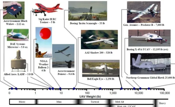
Fig 1.1 Mass Spectrum of Current UAVs ... 13
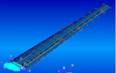
Fig. 2.1 3-D FEM Wing Representation ... 25
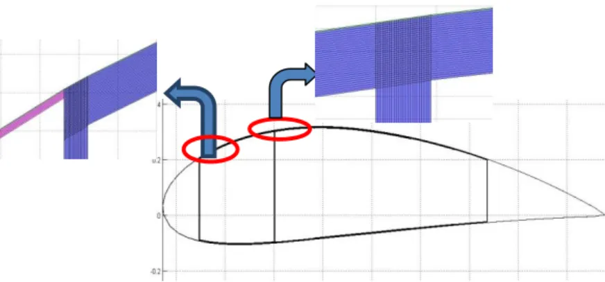
Fig 2.2 Cross-Section at the wing tip and root ... 26
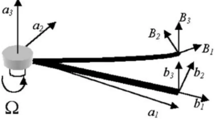
Fig 2.3 Global reference frame a, undeformed beam reference frame b and deformed beam reference frame B ... 27
Fig 3.1 A Rectangular Lattice ... 36
Fig 3.2 General airfoil coordinate system ... 37
Fig 4.1 Main wing analysis procedure ... 49
Fig 4.2 Complete aircraft analysis procedure ... 50
Fig 5.1 Cross-section of the present high aspect-ratio wing ... 62
Fig 5.2 Mode shapes of the single main wing by the 3-D FEM model predicted by NASTRAN ... 67
Fig 5.3 Mode shapes of the single tail wing by the 3-D FEM model ... 68
Fig 5.4 Mode shapes of the single main wing by the Euler-Bernoulli beam structural model ... 69
Fig 5.5 Theodorsen’s function for N=4 ... 70
Fig 5.6 Wagner’s function for N=4 ... 71
Fig 5.7 Flutter analysis by the EB beam structural model and the FS dynamic inflow unsteady aerodynamics model for the main wing ... 75
Fig 5.8 Damping and Frequency plots by the 3-D FEM and the EB beam structural model for the main wing at M 0.5, non-matched flutter solution... 76
Fig 5.9 Damping and Frequency plots by the 3-D FEM model for the tail wing at M 0.5, non-matched flutter solution ... 77
Fig 5.10 Damping and Frequency plots by the 3-D FEM model for the complete aircraft at M 0.5, non-matched flutter solution ... 78
List of Tables
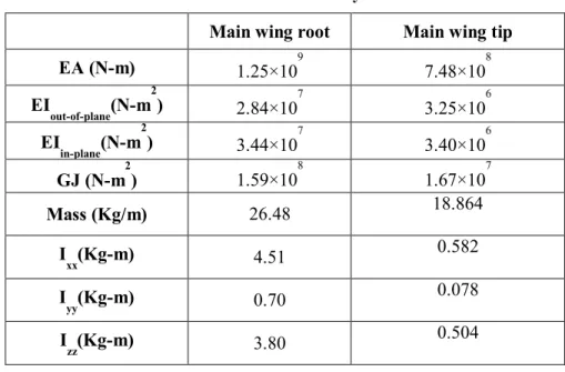
Table 5.1 Cross-sectional analysis results ... 63Table 5.2 Natural frequencies of the single main wing ... 64
Table 5.3 Natural frequencies of the single tail wing ... 65
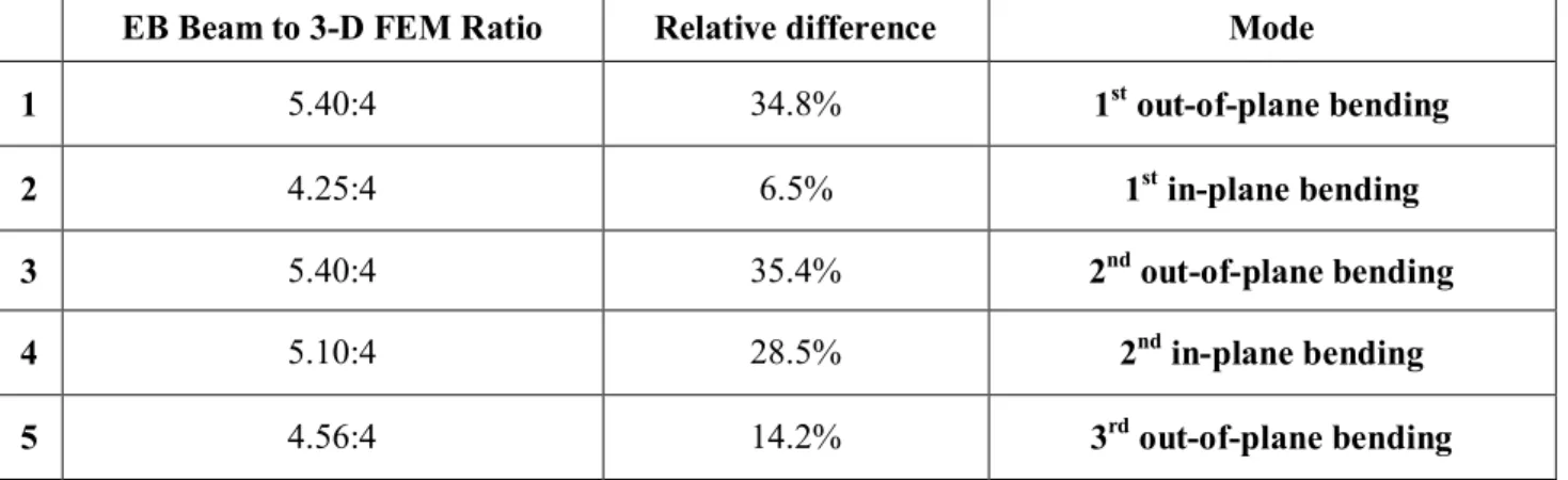
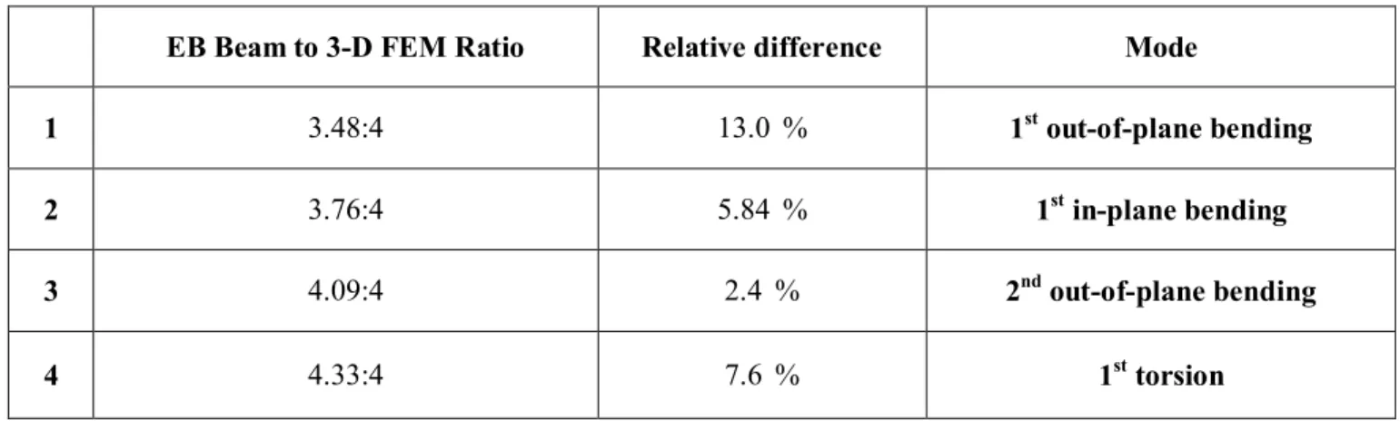
Table 5.4 Comparison upon the natural frequencies of the single main wing ... 66
Table 5.5 Main Wing Flutter Prediction Results ... 72
Table 5.6 Tail Wing Flutter Prediction Results ... 73
Table 5.7 Complete Aircraft Flutter Prediction Results ... 74
Chapter 1. Introduction
1.1 MALE Aircraft
An unmanned aerial vehicle, also known as a drone, is an aircraft without a human pilot on board. The flight of the unmanned aerial vehicles (UAVs) can be controlled in several ways, including flight controlled autonomously by computers in the vehicle itself, by a pilot on the ground or in another vehicle, or remotely controlled by a navigator. UAVs are built in a vast array of shapes, sizes, configurations, and defining characteristics suitable to the execution of an increasing number of operations. With the advancements of more elaborate autonomous control mechanisms, UAVs have been capable of fulfilling more complex and demanding tasks since their beginnings as simple, remote-controlled aircraft.
Varying nomenclature is used to differentiate the classes of UAVs and their individual or class-specific purposes, and the terms ascribed to the individual UAVs varies among those employed for military, research, manufacturing, or professional purposes, among others. The various nomenclatures and classes are based on a variety of parameters, including mass, vehicle configuration, designed application, level of autonomy, type
of operation, or military-level employment. However, there is currently a lack of consensus for classification of civil UAVs, although both the UK and Australia have developed their own classifications between ‘small’
and ‘large’ UAVs based on mass [1,2].
To ensure uniformity with current manned aircraft’s regulation, UAV classifications were considered with mass as a primary distinguishing characteristic. Performance capabilities were analyzed with respect to mass to determine if natural breakpoints in performance were present, which then allowed classifications to be representative of common operating characteristics.
The five main classifications of current UAVs are ‘Micro’, ‘Mini’,
‘Tactical’, ‘Medium Altitude’, and ‘High Altitude’. ‘Medium’ and ‘High’
altitude UAVs are also known as ‘medium-altitude long-endurance’
(MALE) or ‘high-altitude long-endurance’ (HALE) UAVs respectively, indicating their ability to stay aloft for long periods of time. Examples of the UAV mass spectrum are shown in Fig 1.1, along with potential classification boundaries.
A medium-altitude, long-endurance unmanned aerial vehicle (MALE UAV) flies at an altitude window of 10,000 to 45,000feetfor extended durations of time, typically 24 to 48hours. With their advanced Western- Standard, electro-optical payloads, American, Iranian, and Turkish-
developed MALE UAVs are considered the most advanced in the world.
These countries hold a large market share of the MALE UAV market.
Some examples of MALE UAV systems are TAI Anka (Turkey), MQ-1 Predator, Scaled Composites Model 395 (USA), Shahed 129 (Iran), Chengdu Pterodactyl I (China), and DRDO Rustom (India).
Over the past few years there has been a growing need and demand for medium-altitude, long-endurance aircraft. Medium-altitude, long- endurance aircraft, abbreviated in the present research as MALE aircraft, is designed for long-range and long-endurance intelligence and surveillance purposes. For instance, MALE aircrafts are suited to execute a broad range of intelligence and surveillance-related tasks, including monitoring environments for nuclear or chemical contamination, target acquisition, reconnaissance missions, aerial refueling, strategic missile defense, cellular telephone relaying, meteorology, weather forecasting, and numerous others. When compared to other aircraft, the use of a MALE aircraft affords great advantages in the execution of these and other related tasks. The many benefits of MALE aircraft are largely the product of their design; for instance, MALE air vehicles are generally smaller than most other manned air vehicles and accordingly cost less to operate, as fuel and hangar costs are much lower. Moreover, the expenditures that are human- related are minimal, as the absence of a pilot affords an optimized interior of the UAV because it does not require any seat or complex instrument
panels requisite for human operation. With the great technical advancements and the ever-increasing amount and complexity of tasks to which they are aptly suited and engaged, the analysis of all aspects of unmanned aerial vehicles has been elevated to an endeavor of utmost importance.
1.2 Background and Motivation
One of the most distinguishing features of MALE aircraft design is the incorporation of high aspect-ratio wings, although MALE aircraft are also equipped with medium high aspect-ratio wings. In the present research, high aspect-ratio and flexible wings are considered. These high aspect- ratio wings, with their long and slender design, are able to maximize the lift-to-drag ratio, but can also be subjected to large deformations under normal operating loads, leading to geometrical nonlinear behaviors. It is because of these possible deformations and nonlinear behaviors that the investigation of the aeroelastic phenomena acting upon high aspect-ratio wings is of utmost importance; understanding the structural behaviors, both linear and nonlinear, of the wings and the unsteady subsonic aerodynamic forces that act upon them is an important facet of understanding the behavior of the aircraft as a whole.
Extensive improvements and developments in the field of high aspect-
ratio wings in recent decades have merited intensified study and research, quite similarly to the study of fixed rotary-wing aeroelasticity, the drastic improvements of which have also the subject of extensive analysis in recent years. However, whereas the increased study of fixed and rotary- wing aeroelasticity heralded the publication of several review articles and studies in the field [3-4], open literature on MALE aircraft remains minimal. The most prominent study related to MALE aircraft with high aspect-ratio wings was conducted by van Schoor et al., which analyzed the aeroelastic properties of high-altitude, long-endurance (HALE) unmanned air vehicles with high aspect-ratio wings [5]. The authors endeavored to study and account for the aeroelastic characteristics and the control of these highly flexible aircraft. Previous investigations in this field employed linearized modes, including rigid body modes, to predict the stability of the aircraft under different flight conditions. Through these studies, it was concluded that unsteady aerodynamics, combined with the flexibility of the aircraft, provided a better depiction of the problem. The importance of the geometrical nonlinearity in HALE aircraft was further analyzed and highlighted in later studies: see [6-8]. The above-mentioned works concluded that the linear analysis based on the undeformed shape may not be accurate in the case of HALE aircraft with high aspect-ratio wings.
Furthermore, in reference [9], investigations were carried out to explore the effects of large payload-induced deformations and the effects of
fuselage parameters and horizontal tails on the flight dynamics of these highly flexible aircraft. Another major undertaking in this work was to account for the resulting increases in sensitivity of some aeroelastic characteristics upon altering configuration parameters. This increased sensitivity was later identified to be the result of the strong coupling of the highly flexible structure and aerodynamics. Given the findings in this work, it becomes apparent that for highly flexible aircrafts such as MALE aircraft, the coupled effects of large deflection due to structural flexibility and flight dynamics (e.g., roll controllability) as well as other aeroelastic effects (e.g., gust response, flutter instability) must and can be properly accounted for by applying a proper aeroelastic formulation.
Determining the dynamics of high aspect-ratio wings has also been the subject of considerable research, both analytical and numerically based.
However, these dynamics are difficult to obtain accurately since the deformation in two in-plane and out-of-plane motions and rotation, together with the wing geometry, produce significant nonlinear effects.
Hence, many degrees of freedom (DOFs) and higher order nonlinear terms are required in order to create an accurate dynamic modeling of the system.
Historically, linear structural models were used for the study of aeroelasticity of aircraft wings [10-11]; however, nonlinearities are present in one form or another. For example, the structural nonlinearity may appear as a spring with free-play, hysteresis, or cubic nonlinearities; these
types of nonlinearities were investigated by Woolston et al. [12] for a two- dimensional airfoil performing pitching and plunging motions. An alternate approach was suggested by Shen [13] using the well-known Kryloff and Bogoliuboff [14] method in nonlinear vibration theory. For moderate deflections, the nonlinear structural equations of a wing in vertical and torsional motion using a second order nonlinear beam theory were given by Hodges and Dowell [15]. This beam theory is characterized by mixed-form formulations, where displacements and strains are both considered as independent variables. Lee and Leblanc [16] described a method for nonlinear aeroelastic analysis without the limitations in the earlier works by using a time-marching finite-difference scheme. In this method, using incompressible aerodynamics, the aeroelastic equations for a two-dimensional airfoil performing plunging and pitching motions were written as a pair of simultaneous finite difference equations. The effect of initial conditions on the nonlinear behavior was studied numerically by varying the displacement from equilibrium of the pitch angle at the start of the airfoil motion. More detailed studies were later carried out by Price et al. [17] who computed power spectral densities, phase space plots, Poincare maps and Lyapunov exponents of the airfoil response to investigate the possibility of chaotic behavior for certain airfoil parameters.
Lee et al. [18] investigated the nonlinear aeroelastic response of a two- dimensional airfoil considering cubic stiffness nonlinearity in both pitching
and plunging motions. Mook et al. [19-21] indicated that the aerodynamic nonlinearities alone could be responsible for limit cycle oscillations. Patil et al. [22] used geometrically exact structural analysis and finite state unsteady aerodynamic with stall. In their work, they modified Peter’s aerodynamic theory by considering stall corrected expressions to release used theory from any experimental test on a particular airfoil. They showed that stall limits the amplitude of post-flutter unstable oscillations.
Using second order nonlinear beam theory with ONERA dynamic stall model, Tang and Dowell [23-24] compared experimental and theoretical aeroelastic responses of a high aspect-ratio three-dimensional wing with a slender body at the tip and studied the effects of geometric structural nonlinearity and steady angle of attack on nonlinear aeroelastic response of high aspect-ratio wings. Tang and Dowell [25] also demonstrated that the onset of a limit cycle oscillation is dependent upon a delicate balance between stall aerodynamics and structural nonlinear forces.
The importance of aerodynamic and structural geometrical nonlinearities in aeroelastic behavior of high aspect-ratio wings was studied by Patil and Hodges [26] using doublet-lattice aerodynamic theory along with nonlinear finite element beam model. In addition to that, Palacios, et al. [27] have developed an analysis framework based on mixed-form beam theory, which can model slender beams with embedded piezoelectric materials. Displacement-based or mixed-form beam theories
may be used for different applications with different emphasis. One aspect that should be considered during structural analysis is the compatibility of the selected formulation; for example, if the theory selected for structural modeling and analysis may facilitate the analysis of controls and aerodynamics, this proves to be greatly beneficial in creating a comprehensive analysis. A strain-based beam formulation has also been adopted in previous studies, which was originally developed for the modeling of highly flexible aircraft with embedded active materials. High aspect-ratio wings have been modeled as slender beams, whereas the fuselage was treated as a rigid body. The two-dimensional finite state inflow theory has been used for unsteady aerodynamic modeling [28]. An explicit integration method has been implemented for the time marching solutions. Brown, et al. [29] employed a rigid body free to roll, with a coupled bending and twisting deformation to model the effects of the strain actuation on the behavior of highly flexible high aspect-ratio wings.
Cesnik, et al. [30] have introduced flexibility of fuselage and vertical tails to the analysis by following the initial contribution on the strain-based framework. Shearer et al. [31] and Su [32] have also attempted to analyze the nonlinear flight dynamics and the aeroelastic response and of a HALE aircraft, respectively. The method used by the first endeavored to incorporate low order nonlinear strain-based equations along with unsteady finite state potential-flow aerodynamics. As for the subsequent
study, the author focused on the investigation of the nonlinear aeroelastic stability with a special emphasis on a trim state-dependent stability boundary.
1.3 Research Objectives and Approach
In this research, an aeroelastic analysis of the high aspect-ratio wings of a MALE aircraft will be developed and validated. These aircraft are able to effectively perform medium-altitude, long-endurance surveillance missions largely because of their structural design, such as their long, slender wings, which allow for a maximized lift-to-drag ratio. One of the numerous advantages of the adopted approach is that it encompasses every important aspect of both structural and aerodynamic modeling. In addition, when compared to previous works in the field, it represents a significant advancement in terms of computing times. This research endeavors to develop an accurate analysis of the high aspect-ratio wings through the development of in-house tools that offer significant advancements that ensure the reduction of the problem’s complexity while encompassing all its important aspects.
The first order of research is the extraction of the cross-sectional inertia and stiffness properties using the Variational Asymptotic Beam Sectional Analysis (VABS) [33]. With this in mind, the free vibration analysis will
be carried out and natural frequencies will be obtained, which will allow for an aeroelastic response analysis to be performed with the first few modes. However, MALE aircraft may also undergo large deformations under normal operating loads leading to a geometrically nonlinear behavior. Consequently, nonlinearities will be considered in the last phase of this research. A nonlinear model would facilitate the study of other important aspects of MALE aircraft such as the trim effect. In addition to this, the next phase will also comprise investigations on the effects and inherent consequences of the inevitable interaction between rigid-body flight dynamics and aeroelastic modes.
1.4 Thesis Organization
Following this introduction, a range of structural and aerodynamic models used for aeroelastic computations are described separately in Chapters 2 and 3. Chapter 4 integrates the structural and aerodynamic chapters into several flutter analysis models: an Euler-Bernoulli beam structural model with the finite state dynamic inflow unsteady aerodynamics as well as the doublet-lattice method mixed with both the Euler-Bernoulli beam and the three-dimensional finite element structural models. Results from these aeroelastic models focus on the effects of aerodynamics, beam geometry, linearities as well as nonlinearities from
structural and aerodynamic origins to formulate a prediction of critical aeroelastic flutter behavior. Chapter 5 incorporates all the numerical results and finally Chapter 6 summarizes the contributions of this research and suggests avenues for future work.
Fig 1.1 Mass Spectrum of Current UAVs
Chapter 2. Structural Modeling
This chapter introduces the three structural models which are employed and analyzed in the present thesis. First, Euler-Bernoulli beam structural model is described. Many studies used a similar formulation, and the present work highlights the features of the structural model developed based on this approach. Secondly, a three-dimensional finite element model, which best describe the complex structure of MALE aircraft, is presented and used to validate the previous model. The third and final model is a geometrically non-linear beam model that has been used previously for rotary wing structural analysis. In this research, the latter model was adopted to cast the non-linear behaviors within the high aspect- ratio fixed wing.
2.1 Euler-Bernoulli Beam Structural Model
At the very beginning of the structural analysis, an Euler-Bernoulli beam structural model, which is displacement-based, was adopted. With this model, linear analysis is very accurate with comparatively small deformations relative to the size of the overall structure and when there are no large torsional effects present.
The Euler-Bernoulli beam equation arises from a combination of four distinct subsets of beam theory; the kinematic, constitutive, force resultant, and equilibrium definition equations. The outcome of each of these segments is summarized here:
Kinematics: dw
k = - = -q dx (2.1) Constitutive: s( , )x y =E x ye( , ) (2.2) Resultants: M x( )=
òò
y' ( , )s x y dydz (2.3)( ) xy( , )
V x =
òò
s x y dydz (2.4) Equilibrium: dMdx =V (2.5) dV p
dx = - (2.6) While p is the distributed loading acting in the same direction as y (and w), E is the Young’s modulus of the beam. To relate the beam’s out-of-plane displacement w to its pressure loading p, the results of the four beam sub- categories are combined in the order shown below,
Kinematics => Constitutive => Resultants => Equilibrium => Beam Equation
First, when one attempts to combine Eqs. (2.5) and (2.6) to eliminate V,
2 2
d M p
dx = - (2.7) Next, by replacing the moment resultant M with its definition in terms of the direct stresss ,
( )
2
2 ( , )
d y x y dydz p
dx
òò s
= - (2.8) Using the constitutive relation to eliminates in favor of the straine, and then using kinematics to replaceein favor of the normal displacement w,( )
2 2 2
2 2
2 2
2
2 2
d E y dydz p dx
d d
E y dydz p
dx dx
d d w
E y dydz p dx dx
e c
= -
æ ö = -
ç ÷
è ø
æ ö
ç ÷=
è ø
òò òò
òò
As a final step, recognizing that the integral overy2is the definition of the beam’s area moment of inertia I, I =
òò
y dydz2 , allows to get the Euler-Bernoulli beam equation,
2 2
2 2
d d w
EI p
dx dx
é ù
ê ú=
ë û (2.10) If E and I do not vary with x along the length of the beam, then the beam equation simplifies to,
(2.9)
4 4
EI d w p
dx = (2.11) The analysis that has been carried out emphasizes the one-dimensional structural properties of that beam, which was selected for its simplicity and computational speed as opposed to more complex elements such as three- dimensional finite element models. The linear behaviors of the high aspect-ratio wings and forces that can act on the flexible wing were also investigated. Generally, these behaviors are examined by modeling the aircraft wing as a structural beam so that this beam theory may be implemented, the analysis of which is afforded while several geometric limitations are placed on the wing. A major limitation of this model has been the inability to accurately determine the limitations on the wing and to clarify the accuracy of the structural analysis method. Bearing this in mind, this research also uses a three-dimensional finite element structural model and will therefore overcome these limitations and serve as a validation tool for the accuracy of the above-mentioned Euler-Bernoulli beam structural model.
As a starting point, the degrees of freedom had to be defined, followed by obtaining mass and stiffness matrices from the minimum energy kinetic principle. Afterwards, a modal analysis study that covers calculation of natural frequencies and mode shapes of the structure is performed.
‘Natural frequency’ can be defined as the frequency at which free vibration
of the system can take place and ‘Mode Shape’ is the deflection of the points on the structure for that mode. Deflection values in the mode shape matrix are not absolute deflections; they should be either normalized to unity or normalized with respect to the mass matrix. Free vibration of a structure can be formulated as given in Eq. (2.12).
{ }
[ ]M q&& +[ ]{ } [ ]{ } {0}C q& + K q = (2.12)
M is the mass matrix, K is the stiffness matrix and C is the damping matrix of the system. For undamped systems the damping matrix C equals to zero and Eq. (2.12) reduces to
[ ]M q
{ }
&& +[ ]{ } {0}K q = (2.13) Assuming harmonic free vibrations, the displacements can be defined as{ } { }q = u ei tw (2.14) Substituting in Eq. (2.12)
2[ ]{ } [ ]{ } {0}M u K u
w
- + = (2.15) This equation is an eigenvalue problem, the eigenvalues are the squares of natural frequencies and the eigenvectors represent the mode shapes. The mode shapes and modal frequencies of the structure are calculated using the above Euler-Bernoulli beam structural model and are later validated with those from the finite element model. The natural frequencies will be given in Chapter 5.
2.2 Three-Dimensional Finite Element Model
The goal of a structural dynamic analysis includes determining the natural mode shapes and frequencies of an elastic structure in free unforced vibration. The finite element’ modeling is well suited for this type of analysis because mode shapes can be accurately derived for geometrically complex structures. The finite elements structural model is typically formulated as an eigensystem, where the eigenvalues and eigenvectors represent the natural frequencies and the mode shapes respectively. The lowest eigenvalues correspond to the lowest characteristic frequencies of the physical system and are typically more useful than the higher modes simply because the physical system tends to experience the lower modes as dominant vibration frequencies.
Therefore, the equations of motion are derived by systematically accounting for the work done by all internal and external generalized forces acting against the corresponding displacements of the system degrees of freedom. The generalized forces contributing to the transfer of work include gravitational, inertial, internal elastic, damping, aerodynamic, distributed, and point forces. The work contributed by each of the generalized forces is equal to the magnitude of the force times the corresponding displacement. The work that is due to distributed forces and moments is integrated over each element based on the assumed
displacement functions for the finite element. Figure 2.1 shows the three- dimensional finite element wing construction.
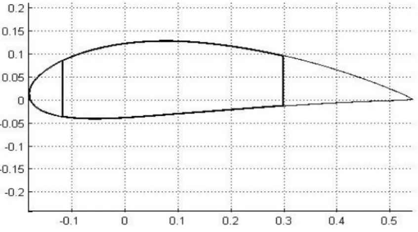
VABS conducts a modeling of the cross-section of the high aspect-ratio wing. VABS implements a rigorous dimensional reduction from the three- dimensional description to a one-dimensional model [33]. The cross- section of a high aspect-ratio wing is presented in Figure 2.2. The inertial and stiffness properties will be presented in the numerical results.
In the free vibration analysis of high aspect-ratio wing structures, the wing structure is equated to a long slender beam capable of bending and torsion. For many classical beam cross-sections, the cross-section is doubly symmetric about both horizontal and vertical axes. This double symmetry leads to an uncoupling of bending and torsional motion.
However, even in simple classical wing structures, the cross section has only single symmetry or no symmetry. This loss of cross-sectional symmetry leads to a coupling effect of bending and torsional motion due to an offset of the center of gravity and the center of shear. The resulting coupled equations of motion are dynamically coupled but elastically uncoupled.
In other words, the linear finite element analysis is fairly accurate for a beam that may bend and has small deflections. If large torsional loads are applied, a highly twisted wing is used, or the deflections are large, it may be necessary to use non-linear analysis to obtain an accurate result.
Moreover, if the material used for the wing is highly flexible, which is the case of high aspect-ratio wings, a linear analysis will not be sufficient. A flexible material will also exhibit coupling between the two transverse bending degrees of freedom which must be accounted for in the off- diagonal terms within the stiffness matrix.
2.3 Geometrically Non-Linear Beam Model
The aforementioned explanation highlights the importance of using a geometrically non-linear beam model. A non-linear structural model was introduced in order to incorporate the important effects of nonlinearities in the analysis of a high aspect-ratio wing. The adopted non-linear approach is based on the variational formulation for moving beams in global frame, which has also been used for rotorcraft (especially for the hover condition) [34]. This method involves the implementation of the non-linear beam formulation without any simplifying ordering scheme that affords a much more accurate and all-encompassing analysis of the high aspect-ratio wings. Additionally, the transformation of the beam’s natural reference frame to a global frame is achieved while enabling the whole analysis to become more simple and precise without destroying its compactness.
Among other indisputable advantages that it provides, this method also ensures that there is no degree of freedom reduction required to determine
the nonlinearities.
The global frame used along this beam formulation is illustrated on Fig.2.3. Displacement, cross-sectional rotation and all the relevant data are formulated accordingly. The rotation matrix C C C= ab Bais expressed as
1 4 2
1 4
T T
C T
q q q qq
q q
æ ö
- D - +
ç ÷
è ø
=
+
%
(2.16)
where
D
is a 3x3 identity matrix.The variational formulation can be written as
2
1
2
1
1
* * * * *
1 0
1
* * *
1 0
( ( )
( ) ( ) ( ))
t
T T T T T
B B B B B B B
t
t
T T T
B B B B B B B
t
V P H F M F dx dt
M P V V H Wdx dt W
d d dg dk d g g
d k k d d d d
+ W - - + - +
- - - - W - W + =
òò
ò ò
(2.17)
wheret1andt2are arbitrary fixed times,d Arepresents the virtual action at the ends of the beam and time interval, anddW is the virtual work of the applied loads. The asterisked * terms means that they satisfy the geometrically exact equations. Therefore, each term of Eq. (2.17) is transformed to the global frame that was introduced in the previous paragraph.
The external force and moment vectors are denoted by fa andma respectively. The ‘hatted’ terms are the boundary values of the
corresponding quantities. The strain, force, velocity and momentum are related through the following equations
[ ]
, 00
B B B
B B B
F P m V
M S H I
g k
ì ü ì ü ì ü é D ùì ü
= =
í ý í ý íî þ ý êë ú Wûí ý
î þ î þ î þ (2.18)
where [S] is a 6x6 cross-sectional stiffness matrix, m is the mass density per unit length, I is the matrix of cross-sectional mass moments/products of inertia. The stiffness matrix is generally obtained through the cross- sectional analysis. Transverse shear stiffness S33andS33are chosen as large numbers since the effect of transverse shear in the one-dimensional model is negligible when applied to slender beams. S44in the [S] matrix includes the trapeze effect, leading to a nonlinear stiffness formulation
55 66
44 44 1
11 material
S S
S S F
S
= + + (2.19)
44material
S represents the torsional stiffness of the unloaded blade and
F
1is the steady-state value of the axial force.Eqs. (2.16), (2.17), (2.18) and (2.19) represent a description of the fully nonlinear beam model, on which the variation of the energy is expressed in terms of components of displacement and rotation in a global frame.
The theory presented is only applicable to a rotating blade, either cantilevered or simply supported in its present understanding.
Consequently, this approach, one that is based on this structural model,
will be modified in order to facilitate an accurate analysis of a fixed wing with an incoming free stream, which will represent a different air-flow pattern when compared to rotary wings. In summary, the use of the geometrically non-linear beam would provide a much more accurate and precise result.
Fig. 2.1 3-D FEM Wing Representation
Fig 2.2 Cross-Section at the wing tip and root
Fig 2.3 Global reference frame a, undeformed beam reference frame b and deformed beam reference frame B
Chapter 3. Aerodynamic Modeling
High aspect-ratio wings reach high aerodynamic efficiency by virtue of their large spans. Except for the regions influenced by the vortices generated at the ends of these wings, the flow over most of the inboard wing section remains two-dimensional. This observation supports the assumption of strip-theory aerodynamics, where the aerodynamic loads at a particular spanwise location are dependent strictly on the geometric angle of attack at that location and are independent of the (three- dimensional) aerodynamic influence of other spanwise locations [34].
This chapter identifies a range of aerodynamic models to describe the aerodynamic loads of the wing. The doublet lattice theory is first described to model the aerodynamics of the wing. Subsequent sections discuss the classical finite state dynamic inflow unsteady aerodynamic theory. The latter is validated and computed in an in-house program.
3.1 Doublet Lattice Method (DLM)
During the mid to late 1960s, a series of events led to the development of a remarkably unsteady aerodynamic tool called DLM. DLM can be used for interfering lifting surfaces in subsonic flow. A complete description of
the development of this theory is provided by References [35-37] which are highly recommended to the interested reader. The following general remarks summarize the essential features of the method.
The theoretical basis of the DLM is linearized aerodynamic potential theory. It is also considered as an extension of the steady Vortex-Lattice method to unsteady flow. The undisturbed flow is uniform and is either steady or varying (gusting) harmonically. All lifting surfaces are assumed to lie nearly parallel to the flow. The method consists of dividing the superficies into a certain number of panels (finite elements aerodynamics).
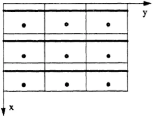
The panels are aligned into the direction of the flow and can either be stationary or harmonically non-stationary. Each of the interfering surfaces (or panels) is divided into small trapezoidal lifting elements (“boxes”) such that the boxes are arranged in strips parallel to the free stream with surface edges, fold lines, and hinge lines lying on box boundaries. The unknown lifting pressures are assumed to be concentrated uniformly across the one- quarter chord line of each box. There is one control point per box, centered span wise on the three-quarter chord line of the box, and the surface normal wash boundary condition is satisfied at each of these points. Fig.
3.1 illustrates the pattern of nine doublet lines for a rectangular wing. The simplicity is that all boxes are treated identically, regardless of its proximity to the wing boundary.
Let’s consider n to be the number of boxes and f dj
m pr
/ 4 the doublet strength in the line segment. fjis the complex amplitude of the force per unit length along the line, and dm represents the incremental length. The normal velocity induced at a point( , )x si i on the surface is, 2
1
( ) / ( , , ( ), ( ))
4
n j
i i i i i j j
j ij
w w x s U f K x s x s d
U m m m
= pr
= =
å ò
(3.1)where each integration is computed over the line segment of length
l
j. If Eq. (3.1) is applied at n downwash points on the surface, the fjare determined. The force on the doublet line is considered as the force on the box and the pressure difference across the surface is then approximated as follows:p
j= force / (box area) = f lj j/ (box area)j jcos j
f x
l
= (3.2)
where
x
jis the box average chord andl
jrepresents the sweep angle of the doublet line.It can be noted that the induced downwash calculated by Eq. (3.2) will be infinite in case the downwash point is located on a doublet line segment or downstream from its end points. Furthermore, the Kutta condition will be satisfied in case each downwash point corresponds to the point at midspan
and on the three-quarter chord line of a box.
In summary, the three main features of the DLM are as follows; it offers good accuracy for subsonic regimes, it is cost competitive with respect to simpler methods such as strip theories and it enables the analysis of complex geometries as well.
3.2 Finite State Dynamic Inflow Unsteady Aerodynamics
Different methods have been used by researchers to efficiently calculate and represent unsteady aerodynamic forces. The early efforts were mainly based on the application of Theodorsen’s theory of unsteady two- dimensional aerodynamics [38]. However, the direct application of Theodorsen’s theory is only limited to the frequency domain analysis and undamped periodic motion, which makes this approach less applicable to control system design and time domain simulation.
Finite-state unsteady models are unsteady aerodynamic approaches which provide more practicality in calculating the unsteady forces and moments [39-40]. Finite state modeling allows one to cast the aerodynamics in the same state-space context as the structural dynamics and controls. This allows the application of advanced time-domain control design techniques to aeroelastic analysis. In Reference 41, the authors developed a two-dimensional finite-state theory that has been the basis for
calculating the unsteady aerodynamic force by many researchers. The theory calculates aerodynamic loads on a thin-airfoil section undergoing large motions in an incompressible inviscid subsonic flow as a function of kinematic parameters and a set of inflow states. Theoretically, an infinite number of inflow states are required to correctly calculate airfoil loads.
However, the desired accuracy can be obtained by using 4 to 8 inflow states. Note that a finite span correction factor has to be applied to account for accurate spanwise force distribution.
In the present research, a finite state unsteady aerodynamics model based on [28] was developed and computed. The use of such a model has several advantages, in terms of computational costs for instance. Besides, there are several other important features of finite state models. First, finite state modeling allows one to cast the aerodynamics in the same state-space context as the structural dynamics and controls. Secondly, the existence of explicit states eliminates the necessity to iterate on solution. This type of finite state aerodynamics offers equations for the induced flow field itself which come directly from the potential flow equations. The states represent induced flow expansion fields rather than velocities. They are hierarchical and consequently, only a few states are needed and the obtained equations are easily coupled with structural equations. For flight simulation of flexible aircrafts, it is necessary to model aerodynamic forces and moments in time domain and express them in motion variables.
The unsteady aerodynamic forces are derived from the finite-state aerodynamic model that is described in Reference [28]. This finite-state type of aerodynamic analysis is very useful in analyzing aeroelasticity because it can be used in the frequency domain, Laplace domain, or the time domain as desired. This model is used here to form a state-space representation of the aerodynamic problem with a low number of states.
Such aerodynamic states are the coefficients of a set of induced-flow expansions.
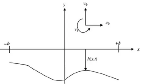
The general airfoil coordinate system on which this theory is developed is presented in Fig. 3.2
The aerodynamic lift and momentum can be written as:
( )
2 3
0
2 ? 1
L=pr¥b - +w U& ¥q&-baq&& + pr¥b æçè- +w U& ¥q+bæçè2-aö÷øq l&- ö÷ø(3.3)
3 1 1
2 8 2
M = -pr¥b æçè- w U+ ¥q -bæçè -aö÷øqö÷ø
& &&
& (3.4)
where = induced-flow velocity and needs to be expressed in terms of airfoil motion. In general, induced-flow theories approximate the effects of shed vortices based on changes they cause in the flow field near the airfoil.
Although the induced-flow varies throughout the flow field, one can approximate its value near the airfoil as an average value along the chord line. The induced-flow theory suggested by Peters et al. (1995) does just that, representing the average induced-flow in terms of N induced-
flow states , , … , as:
0
1
1 2
N n n n
l b l
=
» å
(3.5)where ’s are found by the least-squares method. The induced-flow states are obtained by solving a set of N first-order differential equations approximating the unsteady flow over the airfoil.
[ ]
A{ }
ln +Ub¥{ } { }
ln = c [- +w U¥q+bæç12-aö÷q]è ø
& & & (3.6)
where [A] and {c} are constant matrices and vectors. They are given as follows:
[ ] [ ] { }{ } { }{ }
1{ }
{ }2
T T T
A = D + d b + c d + c b (3.7) where
=
⎩⎪
⎨
⎪⎧ , = + 1
− , = − 1 0 , ≠ ± 1
, =
⎩⎪
⎨
⎪⎧
, = 1
0, ≠ 1
(3.8)
=
⎩⎪
⎨
⎪⎧ (−1) ( )!( !) ( )! , ≠ (−1) , =
, = (3.9)
This finite-state model is in a matrix form that allows it to be easily assembled together with the structural model. For finite-span wings, the modified strip theory that extends the two-dimensional aerodynamics to the three-dimensional case is used. As a result, in the above mentioned equations (3.3) and (3.4) for lift and momentum, the following changes should be implemented:
2 → C θ≡ θ = Λ2π (3.10)
→ b( θπ − ) (3.11)
The model presented above has been computed and validated. For instance, Theodorson and Wagner functions were used to validate the model, the details of which will be provided in Chapter 5.
Fig 3.1 A Rectangular Lattice
Fig 3.2 General airfoil coordinate system
Chapter 4. Flutter Modeling
Flutter is generally observed on wings and control surfaces since these types of structures are subject to large aerodynamic loads. Flutter is produced due to forces that are generated from the dynamic deflections of an elastic structure from the undeformed state [10].
Flutter is defined by a critical speed UF and critical frequency wF. UF is the lowest air speed and wF is the corresponding circular frequency at which a given structure flying at a given atmospheric condition will undergo sustained, simple, and harmonic oscillations. The solution of flutter leads to a complex eigenvalue problem where two characteristic numbers determine the speed and frequency.
The flutter problem has been modeled in various ways, beginning with single degree of freedom models to CFD – CSD coupled solutions. In this chapter, models proposed by various investigators will be presented in order to explain the development in flutter modeling. The approach based on the Doublet-Lattice Method will be explained. Subsequently, the one based on the combination of the geometrically non-linear beam model and the finite state dynamic inflow unsteady aerodynamics will be elaborated.
In the following chapters, the application of these methods along with the
structural models described in Chapter 2 will be presented.
4.1 Flutter Prediction Based on the Euler-Bernoulli Beam Structural Model and DLM
The flight dynamic and aeroelastic system equations of motion can be obtained by combining the structural elastic and unsteady aerodynamic equations. In the present research, for the solution of the aeroelastic system, the steady-state deformation of the wings under given flight conditions is obtained first. The solution provides basic structural data, the distribution of aerodynamic loads in addition to the net forces and moments acting at the body origin. The initial study has been focused on the flutter analysis of the wing using the results by g-Method and k-Method in ZAERO [42], which is based on DLM. In ZAERO, unsteady aerodynamics is estimated upon the structural mode shapes. In other words, two-dimensional panel aerodynamics is applied to the corresponding beam model. Camber and thickness effects with a geometrical shape of an airfoil are then included.
The results obtained from the analysis of both the NASTRAN three- dimensional finite element model and the Euler-Bernoulli beam structural model, are used in ZAERO to perform the flutter analysis.
The original .F06 files are used to analyze the three-dimensional finite element NASTRAN model. Conversely, the flutter analysis for the Euler-
Bernoulli beam structural model is based on the .FRE built files. The aerodynamic states are added to the system matrix within ZAERO doublet- lattice analysis. Consequently, there will be no clear way to distinguish one from another. In fact, even if it is possible to identify each of the modes, the structural modes were influenced by the aerodynamic lag modes that are automatically implemented throughout the analysis. Therefore, all the modes, including structural and aerodynamic ones, will appear. Given these points, when transferring from NASTRAN to ZAERO, the deformation is linearized in terms of mode shapes and natural frequencies.
Thus, while using the Euler-Bernoulli beam structural model, the nonlinearities will likely disappear during the structural analysis.
The flutter matrix equation is derived in the Laplace domain in terms of the generalized mass matrix, M, generalized stiffness matrix K, and the generalized aerodynamic force matrix Q and given through Eqs. (4.1) and (4.2).
2 s L 0= s M K q Q
¥ V
é + - æç ö÷ù
ê è øú
ë û (4.1)
This can be rewritten as:
V 2M p2 2 K q Q p q
( )
0?L ¥
éæ ö + - ù
êç ÷ ú =
êè ø ú
ë û (4.2)
4.1.1 The k-Method
The basic equation for flutter analysis by the k-Method is:
éë-w2M + +(1 ig K q Q ik qs) - ¥
( )
ùû =0 (4.3)It is obtained by replacing
p
by ik in Eq. (4.2), where igsis the added artificial complex structural damping that is proportional to the stiffness.Also, the dynamic pressure q¥ can be written as:
2
1 2 1
2 2
q V L
k r r w
¥ = = æçè ö÷ø (4.4)
where
r
is the air density.The k-Method equation can be obtained by substituting Eq. (4.4) into Eq.
(4.3) and dividing the resultant equation by w2
2
( )
02
M L Q ik K q
k
r l
é + æ ö - ù =
ê ç ÷è ø ú
ê ú
ë û (4.5)
where
( )
2
1 igs
l w
= + is the complex eigenvalue of Eq. (4.5).
To solve for these eigenvalue, unsteady aerodynamic computations must be conducted at several reduced frequencies. These reduced frequencies are defined here as the “reduced frequency list”. Q ik
( )
are generated at given Mach number of interest for each reduced frequency. For a given airdensity
r
, the eigenvalue of Eq. (4.5) in terms of l ’s are solved in the complete reduced frequency list. For n structural modes, there are n eigenvalue corresponding to n modes at each reduced frequency.The flutter frequency
w
f, the airspeedV
f , and artificial damping gsare given in Eq. (4.6):2
( )
1 Re( )
Im Im( ) / Re( )
f
s f
f f
g V L
k
w l
w l l l
w
=
= =
=
(4.6)
4.1.2 The g-Method
The g-Method is a damping perturbation method based. It includes a first order damping term in the flutter equation. This first order term is rigorously derived from the Laplace domain aerodynamics. In the g- Method, it is assumed that a function of Q p( )=Q g ik( + ) exists for
0, 0 g³ g< .
This premise is based on the fact that the Laplace transform of the time domain unsteady aerodynamics for divergent g >0 and constant amplitude motions g=0 is analytic. Due to this analytical continuation,
( )
Q p can be extended along the imaginary axis for small g by means of
a damping perturbation method:
( ) ( )
0
( )
g
Q p Q ik g Q p
g =
= + 
¶ (4.7)
The term
0
( )
g
Q p g =
¶ in Eq. (4.7) is not available in the k-Method. However, if Q p
( )
is analytic, it must satisfy the Cauchy-Riemann equations such that:
(
ReQ p( ) ) (
ImQ p( ) )
g k
¶ 
¶ = ¶ (4.8)
(
ImQ p( ) ) (
ReQ p( ) )
g k
¶ 
¶ = - ¶ (4.9)
Combining Eqs. (4.8) and (4.9) leads to the following general condition:
Q(p) Q(p) g (ik)
¶ = 
¶ ¶ (4.10)
Equation (4.10) is valid in the complete p-domain except along the negative real axis where discontinuity due to a branch cut in subsonic flow occurs.
Thus, the term
0
( )
g
Q p g =
¶ can be replaced by:
'
( )
0 0
( ) ( ) ( )
( ) ( )
g g
Q p Q p dQ ik
g = ik = d ik Q ik
¶ =¶ = =
¶ ¶ (4.11)
Since Q ik( ) can be provided by the k-domain unsteady aerodynamic methods, Q ik'
( )
can be computed from Q ik( ) by a central differencing scheme.Substituting Eq. (4.11) in Eq. (4.7) gives the approximated p-domain solution of Q p
( )
in terms of k and for smallg
:Q p
( )
=Q ik( )
+gQ ik'( )
(4.12) Substituting Eq. (4.12) in Eq. (4.2) yields the g-Method equation:( ) ( ) { }
2
2 2 ' 2
2
1 1
2 2 0
V Mp K V Q ik g V Q ik q
L
r r
éæ ö ù
+ - - =
êç ÷ ú
è ø
ë û (4.13)
4.1.3 Wing Flutter Analysis
In order to analyze the main wing of the aircraft, mass and stiffness matrices were first obtained from the cross-sectional analysis that was carried out using VABS [33]. Afterwards, an evaluation of the structural model of the Euler-Bernoulli beam allowed for the relevant mode shapes and natural frequencies of the beam to be obtained. These properties, as well as the newly-obtained system matrices, were further analyzed and adapted in order to be properly implemented in ZAERO (See Figure 4.1).
To analyze the aeroelastic stability of the Euler-Bernoulli beam structural
model, .FRE files were built and used in ZAERO DLM. Similarly, the three-dimensional NASTRAN finite element model supplied the .F06 files that were utilized for the flutter analysis. The latter was considered as a reference to validate the Euler-Bernoulli beam structural model.
4.1.4 Complete Aircraft Flutter Analysis
For the complete aircraft configuration, the assemblage combination of multiple beams was considered. As for the main wing, both mass and stiffness properties were obtained throughout the dimensional reduction carried out by VABS; which constitutes a tool that enables an efficient high-fidelity cross-sectional analysis. Next, the free vibration analysis results for both main and tail wings were achieved from the Euler- Bernoulli beam structural model’s analysis. Later, this outcome was combined with the properties of the fuselage (See Figure 4.2).
Upon compiling all the data, ZAERO was used to perform the flutter analysis, the results of which were again compared with those obtained by the three-dimensional finite element model.
4.2 Flutter Prediction Based on the Geometrically Non-linear Beam Model and Finite State Dynamic Inflow Unsteady Aerodynamics
The system equations of the combination of the geometrically non-linear
beam model presented in Chapter 2 along with the finite state dynamic inflow aerodynamics from Chapter 3 can be presented as follows
When combining the above two equations, the indexing system of the finite-state of the inflow model must be associated with the mesh of the structural model.
( , ) ( , , ) 0 ( , ) ( , ) 0
s L
I P
F X X F X Y X F Y Y F X Y
- =
- =
& &
& (4.14)
Eq. (4.14) is a well-defined aeroelastic formulation for that combination. It includes geometrical exactness for the structural modeling and three- dimensionality and unsteadyness for the aerodynamics. The result is presented as a set of nonlinear equations and the solutions for Eq. (4.14) can be written as
( ) ( )
X X X t
Y Y Y t
ì ü
ì ü ï ï ï=ì ü+ ï í ý í ý í ý
ï ï ï ï
î þ î þ î þ (
( (4.15)
whereX ,Y are the steady-state components of the solution. They are time independent whileX t(( )
,Y t(( )
are the transient solutions, depend on time.
Solutions of the steady-state and perturbed state cases are obtained by taking advantage of the formulation’s compactness, as described below.
4.2.1 Steady-state Response In this case,X t(( ) 0=
, andY t(( ) 0= The system equations Eq. (4.14) become
( ,0) ( , ,0) 0 ( ,0) ( , ) 0
s L
I P
F X F X Y F Y F X Y
- =
- = (4.16) or simply
( ) ( , ) 0 ( ) ( , ) 0
s L
I P
F X F X Y F Y F X Y
- =
- = (4.17) The solution can be efficiently calculated by the Newton-Raphson method after calculating the corresponding Jacobian matrix that is analytically obtainable.
[ ]
s L L
P L P
F F F
X X Y
J F F F
X Y Y
¶ ¶ 
é - - ù
ê¶ ¶ ¶ ú
= ê ú
¶ ¶ 
ê