- 19 -
Investigation on the Commercialization Issues of Resistive Type Superconducting Fault Current Limiters for Electric Networks
Tae-gun Park
a, Sang-hwa Lee
a, Bang-wook Lee
*,aa
Hanyang University, Ansan, Korea (Received 3 August 2009 accepted 14 October 2009)
Abstract
Among the various types of fault current limiters, superconducting fault current limiters could be the most preferable choice for high voltage electric power systems owing to the remarkable current limiting characteristics of superconductors.
But, there have been no commercial superconducting fault current limiters which were installed into actual electric power systems until these days due to some remained technical and economical problems. Thus, in order to promote the development and application of the superconducting fault current limiters into real field, it is essential to understand the power utilities’ requirements for their networks and also suitable test method and some specifications should be prepared.
This paper focuses on the matters of test requirements and standardization issues that should be prepared for commercialization of superconducting fault current limiters. The unique current limiting characteristics of superconducting fault current limiters were investigated and related other standards including circuit breakers, transformers, reactors, power fuse, and fused circuit breakers were compared to setup the basis of novel specification of superconducting fault current limiters. Furthermore, required essential test procedures for superconducting fault current limiters were suggested.
Keywords : Superconducting fault current limiter, resistive type, inductive type, IEC standards
I. Introduction
S
Uper conducting fault current limiters were considered as novel and smart solutions to control excessive fault current in the electric transmission and distribution networks due to their excellent characteristics. Comparing to other current limiting apparatus such as series reactors, current limiting power fuses, solid state fault current limiters,
pyrotechnique fault current limiters, and circuit breakers, the most prominent characteristics of superconducting fault current limiter is that superconducting fault current limiters are invisible during normal current flowing state owing to zero resistance of superconductors. But during fault state, they could generate some impedance immediately to limit the amplitude of fault current and its duration time very effectively.
Owing to these advantages, superconducting fault current limiters(SFCL) were investigated and developed by many international institutes. Among the various types of SFCL, resistive superconducting fault current limiters using the quench characteristics
*Corresponding author. Fax : +82 31 417 0533 e-mail : [email protected]
School of Electrical Engineering & Computer Science, Hanyang University, Ansan, 426-791 Korea
of superconductor, were commonly investigated and some of them have successfully finished the official field tests [1].
Nowadays, some developers have already fabricated the distribution level of SFCL and were trying to develop transmission-level superconducting fault current limiters [2,3].
But in spite of these research activities and excellent current limiting performances of resistive superconducting fault current limiters, the commercialization and the installation of superconducting fault current limiters have been delayed for some technical and economical difficulties [4].
One of the tasks to be solved for commercialization of superconducting fault current limiters is to understand and satisfy the electric power utilities’ requirements. Then suitable test method and procedures should be prepared to verify the reliability of this novel device. Finally, the international specifications for fault current limiters should be discussed and officially published in the near future.
In this paper, the test requirements and the standardization issues that were pre-requisites for commercialization of superconducting fault current limiters were deeply discussed.
In order to investigate these issues, unique characteristics of superconducting fault current limiters were reviewed and other related standards including circuit breakers, transformers, reactors, power fuse, and fused circuit breakers were compared to setup the basis of novel specification of superconducting fault current limiters.
And finally, essential test items for fault current limiters were suggested considering IEC standards of circuit breakers, power fuse, and fuse-switch combinations.
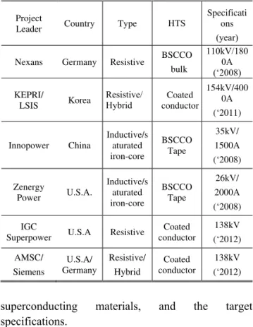
II. Current limiting characteristics of superconducting fault current limiters Table 1 shows a comparison of several super- conducting fault current limiter development programs considering types of current limitation and
Table 1. Developing Status of superconducting fault current limiters(SCFCL)
Project
Leader Country Type HTS Specificati ons (year) Nexans Germany Resistive BSCCO
bulk
110kV/180 0A (‘2008) KEPRI/
LSIS Korea Resistive/
Hybrid Coated conductor
154kV/400 0A (‘2011)
Innopower China Inductive/s aturated iron-core
BSCCO Tape
35kV/
1500A (‘2008)
Zenergy
Power U.S.A. Inductive/s aturated iron-core
BSCCO Tape
26kV/
2000A (‘2008) IGC
Superpower U.S.A Resistive Coated conductor
138kV (‘2012) AMSC/
Siemens
U.S.A/
Germany
Resistive/
Hybrid
Coated conductor
138kV (‘2012)
superconducting materials, and the target specifications.
There were more than 20 projects over the world to develop superconducting FCL at the beginning of 21
stcenturies, but at present, several projects were survived and they were trying to commercialize these novel products to the electric utilities. Their final target is to develop transmission level fault current limiters which would be the biggest markets for these devices. Most of them focuses on the resistive superconducting FCL due to its excellent fault current limiting characteristics, economic feasibility and acceptable size.
In order to satisfy the utilities’ requirements for fault current limiters, a lot of issues to be solved including coordination problems with conventional relays, total operating period and maintenance issues, reliable performances, costs and acceptable size.
These matters were previously introduced by some
literatures [3,4]. Especially in this paper, based on the
reports of superconducting fault current limiters
(Table 1), fault current limiting characteristics were
analyzed and compared to the conventional devices
such as power fuse, circuit breakers in order to
determine the basis of test procedures. And the critical matters to be solved for implementing superconducting FCL to the electric networks were suggested.
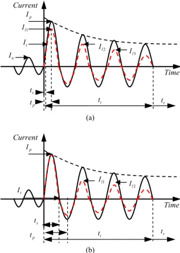
Fig. 1 (a) shows the typical current limiting waveforms of superconducting FCL. Due to the quench phenomena of superconductors by excessive fault currents, most of superconducting fault current limiters were inevitable to respond to fault current and turn to the quench state before reaching the 1
stpeak value of fault currents. In this case, it is essential to determine the reaction time t
sand the amplitude of fault current I at that point. In order to
pcoordinate with relays and series-connected circuit breakers and power fuses, a transfer current which means let-through current not limited by superconducting FCL should be clearly determined.
(a)
(b)
Fig. 1. Current limiting characteristics of superconducting FCL (a) 1
stPeak current limiting type SCFCL(resistive/
inductive type) (b) Non 1
stpeak current limiting type SCFCL(Hybrid type).
In fig. 1 (b), the current limiting waveform which does not limit the 1
stpeak value during half-cycle of the power frequency was shown. The purpose of this device is to coordinate with conventional relays and not disturb the existing protection scheme of electric networks. The working principle of this device was shown in other literature [4].
In order to evaluate the characteristics of superconducting FCL, the set of parameters concerning the behavior of fault current limiters should be determined and they were marked on the waveforms of fault current in fig. 1.
I is the rated current and
nI is the 1
p stpeak value of the prospective current. Parameters concerning the current limiting characteristics are I (1
l1 stcurrent limiting value), I
l2(2
ndcurrent limiting value)
3
I (3
l rdcurrent limiting value). And I
tis the transfer current which could pass the current without any limitation. This value is important to determine the coordination between FCL and circuit breakers and power fuse. In order to operate circuit breakers and power fuse connected in series with FCL, transfer current should be big enough to trip the series connected apparatus.
Regarding as the fault current duration time, following parameters should be determined.
- t
s: elapsed time from fault beginning to the initiation of current limiting action
- t
p: elapsed time from fault initiation to the 1st peak value of limitation
- t
t: total fault duration time before circuit interruption
- t
r: recovery time of superconductors
Those set of parameters should be accurately recorded to evaluate the performance of superconducting FCL and to solve the coordination problems with conventional devices, especially inrush currents were existed in the electric networks.
When a transformer is initially energized, 5~10 times larger transient inrush current could flow for several cycles to the electric networks. As shown in fig. 2, the peak value of the inrush current is could be Current
ts
tt tr
Ip
It
1
I
l2
Il
Time
t
pCurrent
t
st
tt
rI
p 1Il
2
I
l3
I
lI
tI
nTime
t
pFig. 2. Current limiting characteristics when inrush current exists.
(a)
(b)
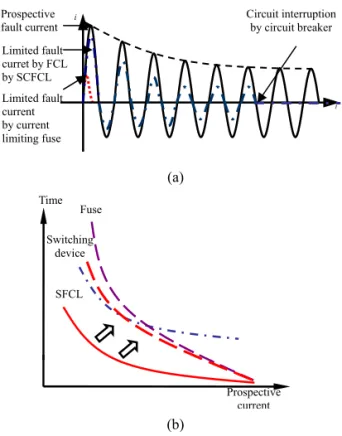
Fig. 3. I-t characteristics of power fuse, circuit breaker, current limiter.
much bigger than the transfer current of superconducting FCL. It means that the inrush current was inevitably limited by FCL. In order to solve this matter, the mitigation device of inrush current should be provided for superconducting FCL and the transfer current should be somehow increased.
Fig. 3 shows the importance of coordination between superconducting FCL and other protecting devices including switching devices, and current
limiting fuses. In fig. 3 (a) current limiting waveforms by FCL and current limiting fuse were compared. One of the important characteristics of superconducting FCL is that it can be resettable comparing to the current limiting fuse. Current limiting fuse cannot be used again after fault clearance. But both devices have current limiting functions. Therefore, characterizing operating sequence between superconducting FCL and current limiting fuse is essential to ensure optimum protection of electric networks.
Power fuse can limit and interrupt fault current itself, but superconducting FCL should be cooperated with the switching device. In this point, fig. 3 (b) shows time-prospective current relations which were essential to determine the performance between FCL and switching device. In case of a superconducting FCL and a switching device installed together, superconducting FCL always working faster than a switching device. At a low fault current or overload current, when superconducting FCL reduces fault current under the setting value of relays, switching device could not work correctly. So in order to solve this matter, the transfer current of superconducting FCL should be increased above the setting value of relay trip. And also the quench signal of superconducting FCL should be delivered to the trip unit of switching device in order to release the trip unit for activating the switching device.
III. Test requirements and standardization of superconducting fault current limiting
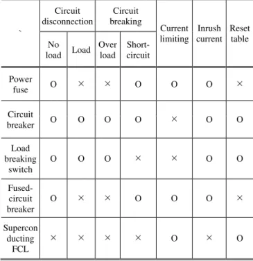
Table 2 shows the characteristics of superconducting FCL compared to other devices.
As summarized in Table 2, Superconducting FCL has no breaking capacity, so it must coordinate with the circuit breaker, and needs to take substantial countermeasures against this problem.
Furthermore, considering the test and standardization of superconducting FCL, it is necessary to take references from current limiting power fuse, circuit breakers and fused circuit breakers.
Prospective current Time Fuse
SFCL Switching
device
t i
Limited fault current by current limiting fuse Limited fault curret by FCL by SCFCL Prospective
fault current Circuit interruption
by circuit breaker Current
Inrush current Prospective fault current Limited Fault current
Time
Table 2. Comparison of the characteristics of circuit interruption & Current limiting devices.
`
Circuit
disconnection Circuit breaking
Current limiting Inrush
current Reset table load No Load Over
load Short- circuit
Power
fuse O ¯ ¯ O O O ¯
Circuit
breaker O O O O ¯ O O
Load breaking
switch O O O ¯ ¯ O O
Fused- circuit breaker
O ¯ ¯ O O O ¯
Supercon ducting FCL
¯ ¯ ¯ ¯ O ¯ O
In addition, the current limiting characteristics of superconducting FCL could be determined by considering the coordination with conventional switching device, relays and current limiting fuses.
The transfer current of superconducting FCL should be increased for this matter, and the working schemes of superconducting FCL should be carefully determined by considering the behavious of current limiting fuse and switching device combined systems.
Table 3 shows the IEC standards to be considered for making standards for fault current limiters.
Especially IEC62271-105, which is the standards for
‘alternating current switch-fuse combinations’ were examined in detail because FCL should be working with switching devices in the electric networks.
In order to develop and test the performance of novel electric device, it is important to characterize its performance and set up the ratings and specifications. Concerning superconducting fault current limiters, following parameters should be defined and these parameters could be used for ratings of superconducting fault current limiters.
Essential parameters of SFCL to specify its performance were defined in Table 4.
Table 3. IEC standards : reference for superconducting FCL
IEC Standard
No. Title Year
IEC62271-100
High-voltage switchgear and controgear-Part100:Alternating-
curent circuit-breakers 2008
IEC60265-1
High-voltage switches- Part 1:
Switches for rated voltages
above 1kV and less than 52kV 1998
IEC60282-1 High-voltage fuses- Part1:
Current-limiting fuses 2005
IEC62271-105
High-voltage switchgear and controlgear- Part105:
Alternating current switch-fuse combinations
2002
IEC60076-3 Power transformer-Part 3:
Insulation levels, dielectric tests
and external clearances in air 2002
Table 4. Rating parameters of SFCL
Parameters Unit
Rated Maximum Voltage kV rms
Rated Continuous Current kA rms
Rated Power Frequency Hz
Prospective Fault Current kA peak
Permissible Fault Current kA rms
Rated Let-through Current kA rms
Rated Let-through Current Duration Cycles
Rated Dielectric Performance - Power Frequency withstand - Impulse, Full-wave withstand - Impulse, Chopped-wave withstand
kV rms kV peak kV peak
Temperature-Rise Degree
Partial Discharge pC
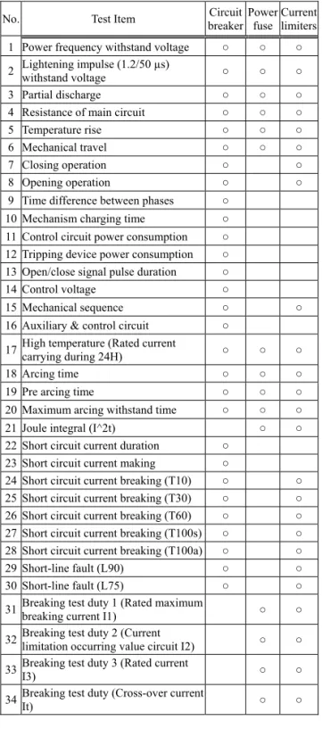
Finally, Table 5 shows the suggested test items for
fault current limiters considering existing standards
of circuit breakers, power fuse. In this table, tests for
cryogenic systems and superconductors were not
included.
Table 5. Comparison of test items for circuit breaker, power fuse and fault current limiters
No. Test Item Circuit
breaker Power fuse Current
limiters 1 Power frequency withstand voltage ○ ○ ○ 2 Lightening impulse (1.2/50 µs)
withstand voltage ○ ○ ○
3 Partial discharge ○ ○ ○
4 Resistance of main circuit ○ ○ ○
5 Temperature rise ○ ○ ○
6 Mechanical travel ○ ○ ○
7 Closing operation ○ ○
8 Opening operation ○ ○
9 Time difference between phases ○ 10 Mechanism charging time ○ 11 Control circuit power consumption ○ 12 Tripping device power consumption ○ 13 Open/close signal pulse duration ○
14 Control voltage ○
15 Mechanical sequence ○ ○
16 Auxiliary & control circuit ○ 17 High temperature (Rated current
carrying during 24H) ○ ○ ○
18 Arcing time ○ ○ ○
19 Pre arcing time ○ ○ ○
20 Maximum arcing withstand time ○ ○ ○
21 Joule integral (I^2t) ○ ○
22 Short circuit current duration ○ 23 Short circuit current making ○
24 Short circuit current breaking (T10) ○ ○ 25 Short circuit current breaking (T30) ○ ○ 26 Short circuit current breaking (T60) ○ ○ 27 Short circuit current breaking (T100s) ○ ○ 28 Short circuit current breaking (T100a) ○ ○
29 Short-line fault (L90) ○ ○
30 Short-line fault (L75) ○ ○
31 Breaking test duty 1 (Rated maximum
breaking current I1) ○ ○
32 Breaking test duty 2 (Current
limitation occurring value circuit I2) ○ ○ 33 Breaking test duty 3 (Rated current
I3) ○ ○
34 Breaking test duty (Cross-over current
It) ○ ○
IV. Conclusion
Until now, no test procedures and standards were prepared for testing of FCL. It was difficult to deduce specific standards for this novel device because there is several types of FCLs, and their characteristics were unique respectively. And it was not easy to apply current standards of circuit breakers and power fuse to the fault current limiters. Therefore, this works could be the fundamental step for establishing the test requirements and standardization of superconducting fault current limiters.
Acknowledgments
This research was supported by a grant from Center for Applied Superconductivity technology of the 21
stCenter Frontier R&D Program funded by the Ministry of Education, Science and Technology, Republic of Korea.
References
[1]
Kreutz. R et al., “System technology and test of CURL10, a 10kV, 10 MVA resistive high-Tc superconducting fault current limiter”, IEEE Trans. on Applied Superconductivity, vol. 15, Issue, 2005.
[2]
H. Schmitt et al., “Fault current limiters - applications, principles and experience”, CIGRE SC A3&B3 joint colloquium, 2005.
[3]
CIGRE WG A3.10: “Fault Current Limiters in Electrical Medium and High Voltage Systems”, CIGRE Technical Brochure, No. 239, 2003.
[4]